
Abstract
Machining accuracy is the most critical indicator to evaluate the machining quality of parts in metal cutting industry. However, it is difficult to be identified before real cutting, because of a variety of error sources presented in a machining process system, such as assembly inaccuracy of machine tool, deformation caused by temperature variation and dynamic cutting force, tool wear, servo lag and so on. Consequently, it is difficult to determine whether a new machining process can satisfy accuracy requirements beforehand. Traditionally, a machining process is validated through the “trial and error” approach, which is time consuming and costly. If machining accuracy can be predicted to a large extent, a rational process can be planned to ensure the precision of parts and even to maximize resource utilization without trial cuts. For this purpose, this work focuses on machining accuracy prediction for five-axis peripheral milling based on the geometric errors. An error synthesis modeling method is proposed to integrate the geometric errors of the process system, including machine tool geometric error, workpiece locating error, cutting tool dimension error and setup error. From a multi-body system point of view, all these errors are synthesized to generate position error of the cutting contact point in the workpiece coordinate system. Then the machining error is obtained by projecting the position error to the workpiece normal vector, which can be measured by a coordinate measuring machine. The prediction model has been evaluated by a cutting test with our in-house-developed prototype software. The result shows that the proposed method is feasible and effective.
Keywords
Introduction
Owing to the presence of different error sources in milling, a new process should be proved to satisfy the accuracy requirement before formal production. Traditionally, it is mainly validated through the “trial and error” method. Obviously, this method is time consuming and costly. If the machining accuracy can be predicted before cutting, there are twofold benefits: (1) the process can be validated to satisfy the accuracy requirement of final parts and further to maximize resource utilization rate, and (2) compensations can be used to improve the machining accuracy. This is meaningful to reduce the production cost.
In the past several decades, many researches have focused on this topic. Typically, in 1977, Wu 1 first proposed forecasting compensatory control (FCC), which was widely adopted to improve machining accuracy. Then, in 1995, the International Academy for Production Engineering (CIRP) started a working group “Modelling of Machining Operations” to develop predictive models for machining performance in order to facilitate effective planning of machining operations to achieve optimum productivity, quality and cost. 2
Generally, previous studies focus on different error sources, mainly including geometric error and thermal error of machine tool, cutting force caused deformation and workpiece locating error. The following related works are classified according to the error sources.
Machine tool geometric error
To predict the machining error caused by geometric error of machine tool structures, a variety of modeling methods have been developed. As early as 1960s, Leete 3 established a geometric error model of a three-axis machine tool by triangular relationship. Then, Fourier transform, 4 variational approach, 5 homogeneous coordinate transformation, 6 rigid body kinematics 7 and multi-body system (MBS) 8 were sequentially applied to machine tool geometric error modeling. And a homogeneous coordinate transformation (HTM)-based modeling method was widely adapted.9,10
Particularly, given the flexibility of the machine tool structures, Wang and Ehmann 11 proposed a method to measure the total position error of a range of nodes in machining space by telescoping ball-bars directly, and then get the position error of an arbitrary tool tip through interpolation algorithm. 12
Machine tool thermal error
Since thermal deformation was first found to be a main factor affecting the precision of machine tools in 1933, many studies have focused on machine tool thermal error prediction and compensation. In the past few decades, finite element method (FEM), 13 HTM, 14 regression analysis (RA), 15 neural network (NN), 16 gray system theory 17 and fuzzy inference 18 were adopted to establish thermal error prediction model.
FEM provides a solution for the temperature and thermal deformation of a machine tool, but its prediction accuracy is low owing to insufficient understanding of the boundary conditions. 16 Additionally, the temperature field and thermal deformation of machine tools change over time; FEM cannot describe this time-varying phenomenon in complex machining conditions. 17
In theory, the HTM-based model is feasible. But in practice, it is difficult to implement because defined error parameters are difficult to detect in real time.
RA-based model is suitable for online real-time compensation because of its simple computing process and fast computing speed. However, its prediction precision is not good, and it cannot describe the complex nonlinear relationship between the temperature field distribution and the thermal deformation of machine tools. 19
For the NN modeling, the biggest challenge is the robustness of the model. Consequently, some improved and hybrid models were developed.19,20
Cutting force caused tool-workpiece deformation
To predict the deformation caused by cutting force, the cutting force should be predicted at first. In the last decades, the analytical method based on cutting geometry calculation and cutting force coefficients identification was widely adopted to establish a cutting force model.21–23 At present, three types of cutting force models are widely used: 22 (1) characterizing the effects of the shearing on the rake face and the rubbing at the cutting edge by a single coefficient,24,25 (2) separating the shearing and rubbing effects with two independent coefficients 26 and (3) using the normal force coefficient, the friction force coefficient and the chip flow angle to characterize the cutting force model. 27
For the deformation caused by cutting force, tool deflection is mainly calculated according to cantilever beam theory; 28 workpiece deformation is mainly calculated through FEM, 21 but it is time consuming and the prediction precision is low.
Workpiece locating error
According to the error source, previous researches on workpiece locating error could be divided into two aspects: (1) geometric error (workpiece offsets owing to geometric error of fixture and workpiece) and (2) deformation error (locators and workpiece deformation due to clamping force and cutting force).
For the first aspect, a Jacobian matrix was widely adopted to establish the relationship between the source errors and the workpiece position/orientation errors. 29 Giving the source errors, the workpiece locating error can be calculated by this relationship model. In addition, other methods such as the method of moments 30 and Monte Carlo simulation 31 were also adopted to establish the workpiece positioning error caused by geometric error.
For the other aspects, besides the traditional elastic mechanic which was adopted to establish the deformation model, 29 finite element analysis (FEA) was popularly adopted too. 32
All above-mentioned error modeling mainly focused on one kind of error source. However, the machining process is affected by many error sources, and the proportion is varied in different processes. So these models cannot predict the machining accuracy of final parts accurately in all cases. Consequently, several models were proposed to integrate more error sources. For example, Yuan and Ni 33 established an error synthesis model including machine tool geometric error and thermal error based on rigid body and small error assumptions. Suneel et al. 34 proposed an integrated product quality model using artificial neural networks (ANN). Li et al. 35 proposed a machining accuracy prediction model integrated GM (1, 1) model, Markov chain model and Taylor approximation method. The ANN and Gray theory–based models have high prediction accuracy because of taking all error factors into account, but a large number of experiment data are needed. In addition, these models are only suitable for a specific process.
The previous researches have confirmed that MBS and HTM are correct and feasible for machine tool geometric error modeling. And the synthesis models considering more error sources can improve prediction precision. Furthermore, this article establishes an analytical synthesis model integrating machine tool geometric error, workpiece locating error, cutting tool dimension error and setup error based on MBS to predict the machining error of any cutting position. According to the machining errors of some picked points, the dimension and form accuracy of final parts can be further predicted, and error compensation and process optimization can be used. Prototype software and cutting test are used to show that the proposed model is feasible and effective.
Error source analysis
The error sources exist in the whole machining process and affect final machining error in different ways. According to the process sequence, this study divided the error sources into three groups: (1) before cutting, (2) in cutting and (3) after cutting, as shown in Figure 1.
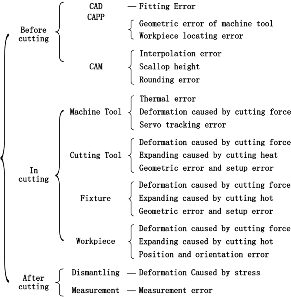
The existence of error sources in a machining process.
Errors generated before cutting
Usually, there are three steps before cutting in a computer numerical control (CNC) machining process: computer-aided design (CAD), computer-aided process planning (CAPP) and computer-aided manufacturing (CAM).
In CAD, if a machining surface is described by a point cloud, there is always a deviation called fitting error between the fitted surface and the original surface.
In CAPP, machining method, machine tool, cutting tool, cutting parameters, cutting scheme and clamping scheme are drafted. Once a machining process is planned, the geometric error of the machine tool and the workpiece locating error are determined subsequently. The cutting parameters will further affect the cutting force, surface roughness and servo tracking error in cutting.
In CAM, a planned process is converted to numerical control (NC) codes. Usually, the machine tools cannot control the tool feeding along freeform curves, but can control straight lines and arcs. Therefore, in programming, a series of discrete points are selected and connected by straight line segments to replace a curve. Consequently, the deviation called interpolation error between the curve and the straight segments is resulted. In addition, scallop height is left over between two adjacent cutting trajectories, and rounding error is generated because of rounding.
Errors generated in cutting
In metal cutting, the process system (machine tool, cutting tool, workpiece and fixture) is affected by cutting force and cutting heat.
For machine tools, the cutting force brings the elastic deformation of the machine tool structures, though it is usually small because of good stiffness of machine tools. And local temperature increase brings thermal deformation of machine tool structures, especially the spindle. Moreover, there is always tracking error between the actual position and the order position.
For cutting tool, its geometry is different from the nominal one because of manufacturing error and wear. And the tool axis may not coincide with the spindle axis during setup. Moreover, the cutting force brings elastic deformation, especially for slender tools, and the cutting heat brings thermal deformation, though it is slight because of the presence of cutting fluid.
For fixture, there are geometric error and setup error as same as cutting tool. And elastic deformation and thermal expansion of locators may emerge due to clamping force, cutting force and cutting heat.
For workpiece, especially thin wall parts, elastic deformation still happens owing to cutting force and clamping force. And the workpiece probably expands because of cutting heat and ambient temperature increasing. In addition, its position and orientation errors in the machining space also affect final machining accuracy.
Errors generated after cutting
After cutting, the machining accuracy is usually detected by a coordinate measuring machine (CMM). But the measured results are always different from the actual positions because of the existence of measurement errors. Moreover, the part may be deformed due to stress relief after it is dismounted from the fixture.
Error synthesis model
To predict the machining error more precisely, this study establishes an error synthesis model integrating the geometric errors of five-axis peripheral milling process system, including machine tool geometric error, workpiece locating error, cutting tool dimension error and setup error. Corresponding prediction process is proposed as briefly shown in Figure 2. First, all the error parameters are measured and stored in a database. Then the error parameter values are loaded into the error synthesis model to predict the position error and the machining errors of some picked machining positions. Moreover, the dimension and form errors of the parts can be further predicted based on the acquired machining errors. Incidentally, the prediction results can be used for error compensation and process optimization.
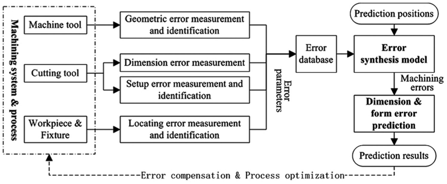
The proposed prediction process.
Error parameter definition
Machine tool geometric error
It is well known that an unconstrained object has six degrees of freedom (DOFs). Accordingly, its position error can be described by six parameters along the DOFs respectively. Similarly, for machine tool, there are six geometric error parameters of each component. Taking X-slideway for example, its six geometric error parameters (ΔXx, Δyx, Δzx, Δαx, Δβx and Δγx) are shown in Figure 3. For a three-axis machine tool, there are 21 geometric error parameters, including positioning error, straightness error, pitch error, yaw error, roll error of each axis and perpendicularity errors between every two axes (Δdij, i = x, y, z; j = x, y, z).
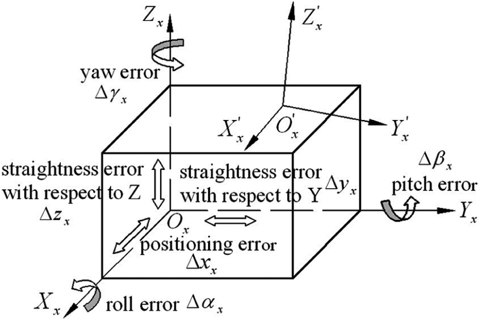
Geometric error parameters of X-slideway.
For multi-axis machine tool, each rotation axis brings its six geometric error parameters too. Figure 4 shows the six geometric error parameters (ΔxC, ΔyC, ΔzC, ΔαC, ΔβC and ΔγC) of a C-rotary table.
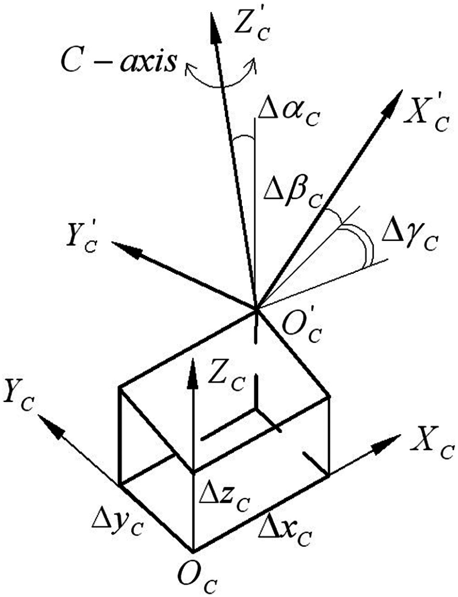
Geometric error parameters of a C-rotary table.
Workpiece locating error
The purpose of locating is to ensure that the workpiece is in a correct position in the machining space during the whole cutting process. But it always deviated from the ideal position owing to the geometric error and setup error of locators. The deviation can be described by the error parameters along six DOFs (Δxw, Δyw, Δzw, Δαw, Δβw and Δγw), respectively, as shown in Figure 5.
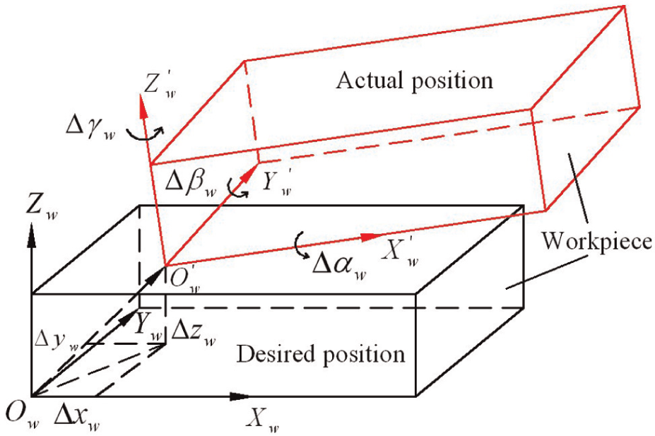
Workpiece locating error parameters.
Cutting tool dimension error and setup error
Cutting tool dimension error mainly includes radius error (ΔRT) and length error (ΔLT). In addition, the clearance between the tool holder and the tool post leads to setup error when tool installation is done. As the tool rotates around the axis of the spindle, the setup error can be described by the error parameters along five DOFs (ΔxT, ΔyT, ΔzT, ΔαT and ΔβT), where ΔxT, ΔyT and ΔzT are consistent with tool run-out errors.
Error synthesis modeling
According to the theory of MBS, a machining process system can be viewed as a kind of MBS composed of workpiece, fixture, cutting tool and machine tool. And the machine tool can be viewed as a sub-MBS composed of workbench, column, spindle, slideways and so on. Taking a XFYZBA five-axis machine tool for example, its structure is shown in Figure 6 and the topological construction of the process system is shown in Figure 7.
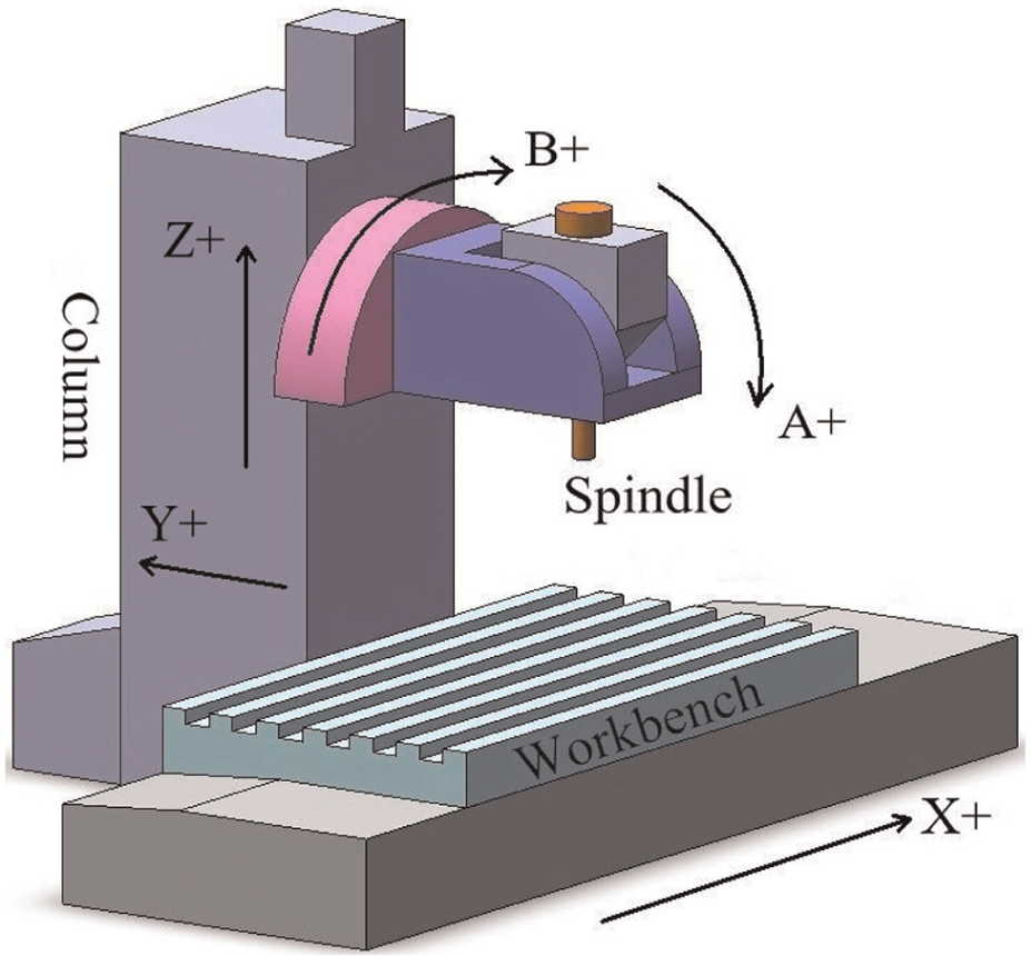
Structure of the machine tool.
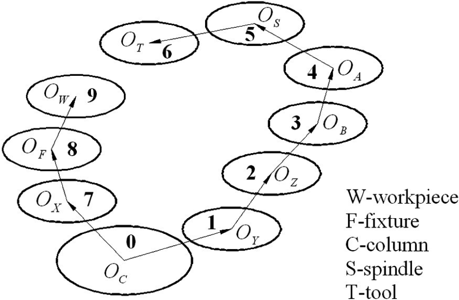
Topological construction of the process system.
Set up a coordinate system for each “body” and use a 4×4 HTM to represent the transformation relationship between a pair of adjacent bodies; the ideal cutting contact point (CCP) Pideal in the workpiece coordinate system (WCS) can be described as equation (1), and the ideal tool orientation
However, in an actual machining process, owing to the presence of errors, the actual transformation matrices are different from the ideal ones.
For cutting tool, owing to the dimension error and setup error, the actual CCP and tool orientation will deviate from the ideal position. From the NC code, the ideal tool tip (TP) coordinate Xi, Yi, Zi (i = 1,2,…,n) and rotation angle Ai, Bi (i = 1,2,…, n) can be obtained directly, and the ideal tool orientation in WCS can be further obtained by equation (3) according to the topological construction of the process system.
In five-axis peripheral milling, the interpolation step is usually small. Therefore, the tangent vector at this position can be looked as the vector from current TP i (i = 1,2, …, n) to next one i+1, as shown in equation (4).
Obviously, the normal vector at this position is the cross product of the tool axis vector
Ideally, the position of CCP in a tool coordinate system (TCS) is shown in equation (6). However, owing to the radius error ΔRT, the actual position of CCP in TCS should be shown as equation (7). Moreover, owing to the length error ΔLT and setup errors, the actual transformation matrix of the tool with respect to the spindle is shown as equation (8).
For spindle, owing to the presence of geometric error, its actual transformation matrix with respect to A-axis is shown as equation (9).
For A-axis, owing to the presence of geometric error, its actual transformation and rotation matrixes with respect to B-axis are shown as equations (10) and (11).
Similarly, the actual transformation and rotation matrixes of B-axis with respect to Z-axis are shown as equations (12) and (13).
For Z-axis, owing to the presence of geometric error, the actual transformation matrix of Z-axis with respect to Y-axis is shown in equation (14).
Similarly, the actual transformation matrixes of Y-axis and X-axis with respect to the column are shown in equations (15) and (16).
For the workpiece and fixture, the geometric error and setup error lead to workpiece position and orientation errors, and then result in deviations of the CCPs. Therefore, the actual transformation matrix of workpiece and fixture with respect to X-axis is shown as equation (17).
Especially, the column is looked as the reference coordinate system without errors, because it is fixed with ground.
Consequently, in conclusion, the actual CCP Pactual and tool orientation
Finally, the machining error ε can be obtained by projecting the position error E to the unit normal vector
Development of prototype software
In order to implement the proposed error synthesis model, prototype software was developed based on Visual Studio 2010. As shown in Figure 8, the prototype software can be divided into three modules: the main program module, the database management module and the display module.
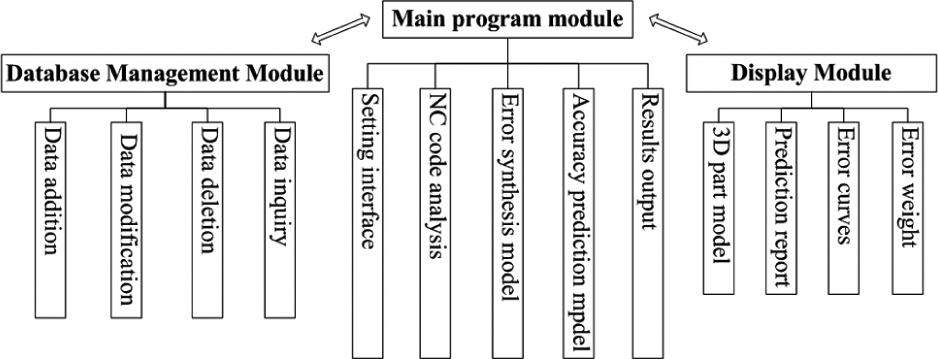
Module structure of the prototype software.
The main program module coordinates all modules to complete machining accuracy prediction, display and output. The process information is set through the interface artificially. The position error and machining error of each prediction point are computed by the error synthesis model. The dimension error and form error of the features are computed by the accuracy prediction model. And the proportions of individual error factors are also computed. The computation result is exported to the graphic display module for display.
In the database management module, Oracle is adopted to store and manage the process information, error parameters and prediction positions, including the functions of data addition, modification, deletion and inquiry. Especially, the error parameters are associated with the process information. For example, once the machine tool is selected, its geometric error parameters are linked and involved in the error calculation automatically.
The display module is based on the OpenGL graphic interface. The three-dimensional (3D) part model can be shown, translated, rotated and zoomed in this module. By receiving the error prediction results from the main program module, the magnitude and direction of the machining errors are displayed on the 3D part model. Moreover, curves of the machining errors and a histogram of the proportions of individual error factors are drawn to show the prediction result intuitively.
Figure 9 shows the flowchart of this prototype software. Previously, the process information, error parameters and prediction positions are added in the database. The error parameters are associated with the machine tools, cutting tools and fixtures, and the prediction points are associated with the machining features. Then, load the 3D model of the prediction part, which will be shown in a view window. Next, select the process system; the error parameters and prediction positions are selected at the same time. After loading the NC code, the error calculation begins, the program matches the NC code and the prediction positions automatically, and the machining errors are computed by the error synthesis model. The computation result is sent to display on the part model and plot error curve. Furthermore, the dimension error and the form error of the selected feature are computed by the accuracy prediction model. Afterward, the proportions of individual error factors are calculated and shown by a histogram. Finally, the process information and prediction results are exported to a text report.
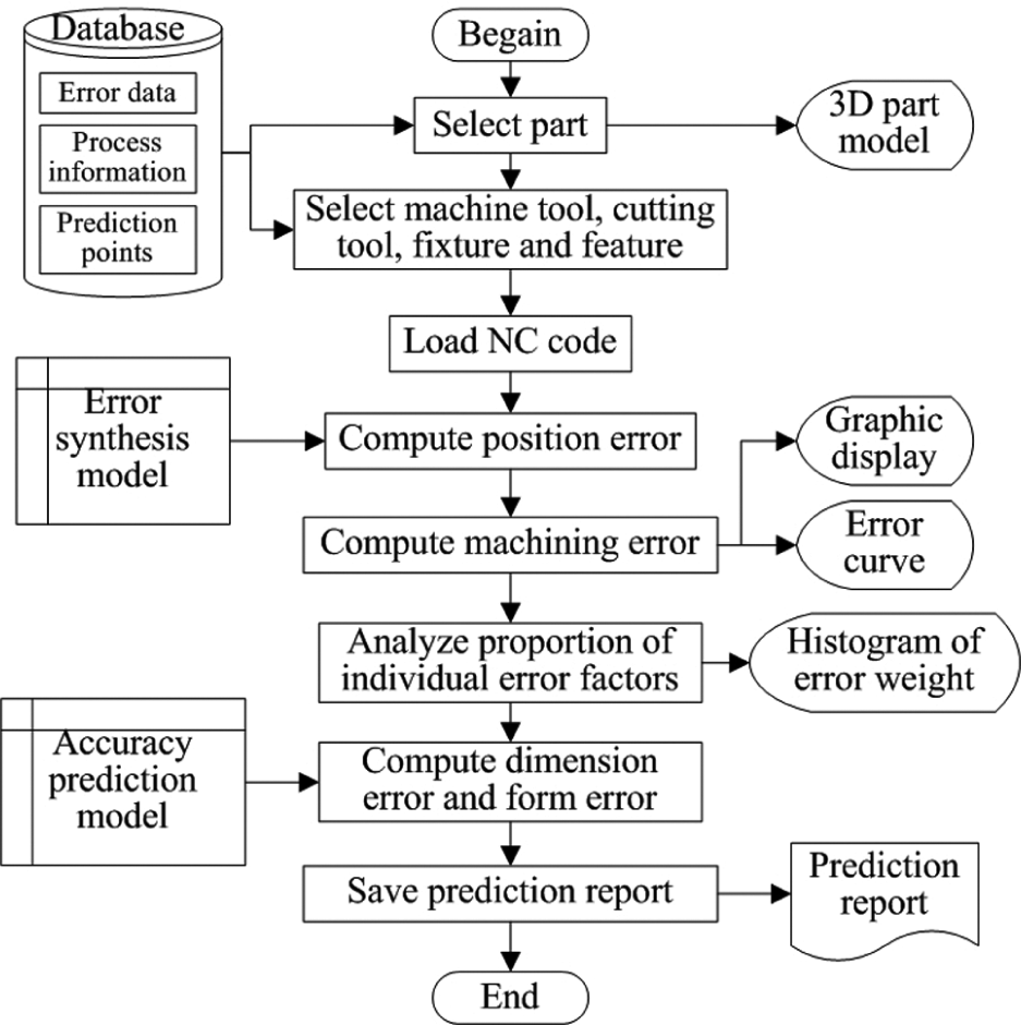
Flowchart of the prototype software.
Experiment and discussions
To verify the feasibility and effectiveness of the proposed model, an experiment was conducted on a XFYZBA structure five-axis machine tool (Figure 6). The finishing process of the part like a distorted letter “S” was selected. Figure 10 shows its tool path.
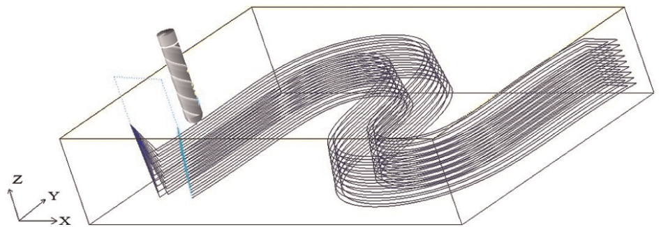
Tool path of the experiment part.
The experiment contains four steps: (1) error parameters measurement and identification, (2) machining error prediction, (3) real cutting and (4) machining error measurement and result analysis. First, the laser interferometer–based 12-line method 36 was adopted to identify the machine tool geometric error parameters. The positioning errors of the 12 lines were measured by a Renishaw XL-30 laser interferometer system, and then the 21 geometric error parameters at each measurement node were identified according to the 12-line algorithm. Figure 11 shows the positioning error identification results of X-axis, Y-axis and Z-axis as an example. In the measurement, thermal error has little effect, because of small change of ambient temperature and short continuous running time of machine tool.
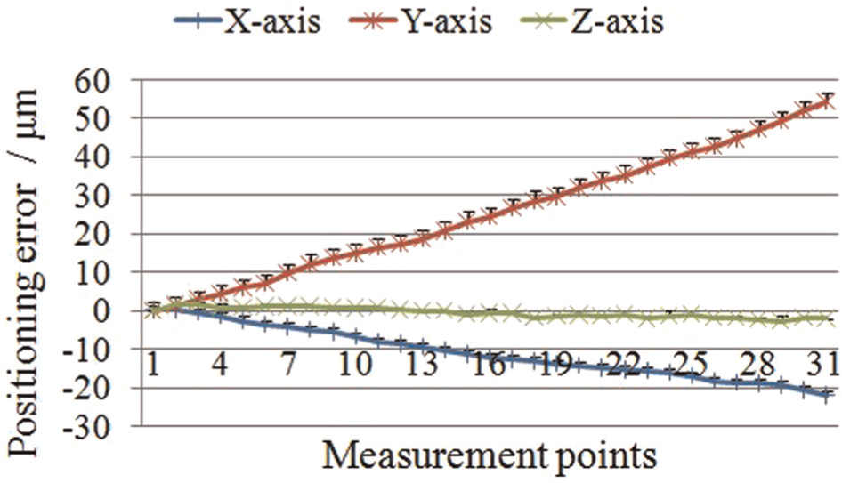
Identified positioning errors of X-axis, Y-axis and Z-axis.
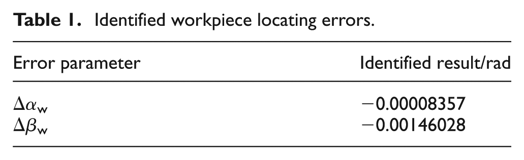
After the workpiece was clamped on the workbench, the coordinates of some picked points on the workpiece surface are detected by a Renishaw probe. Then the workpiece locating errors were identified by the method proposed in literature 37 and the results are listed in Table 1. In this case, only the angular errors around X-axis (Δαw) and Y-axis (Δβw) affect final machining accuracy.
Identified workpiece locating errors.
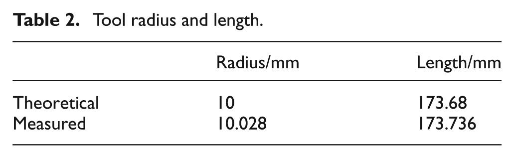
Before finishing operation, the actual radius and length of the tool were measured by a tool detecting device on the machine tool while the tool is rotating. Table 2 shows the nominal values and the measured values, and the dimension errors can be obtained accordingly. In this measurement, the dimension errors contain the setup errors of the tool because it is rotating.
Tool radius and length.
Then, on one hand, the error parameters, process information and prediction points were added into the database and the machining errors of the picked prediction points were predicted and displayed by the software. On the other hand, the finishing cutting was completed and the machining errors of the picked prediction points on the machined part (Figure 12) were measured by a CMM. Figure 13 shows the prediction result and the measurement result contrastively. In the figure, the prediction error is the difference between the measurement result and the prediction result (measured value minus predicted value).
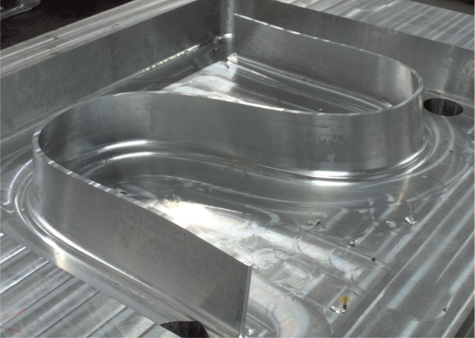
The machined test part.
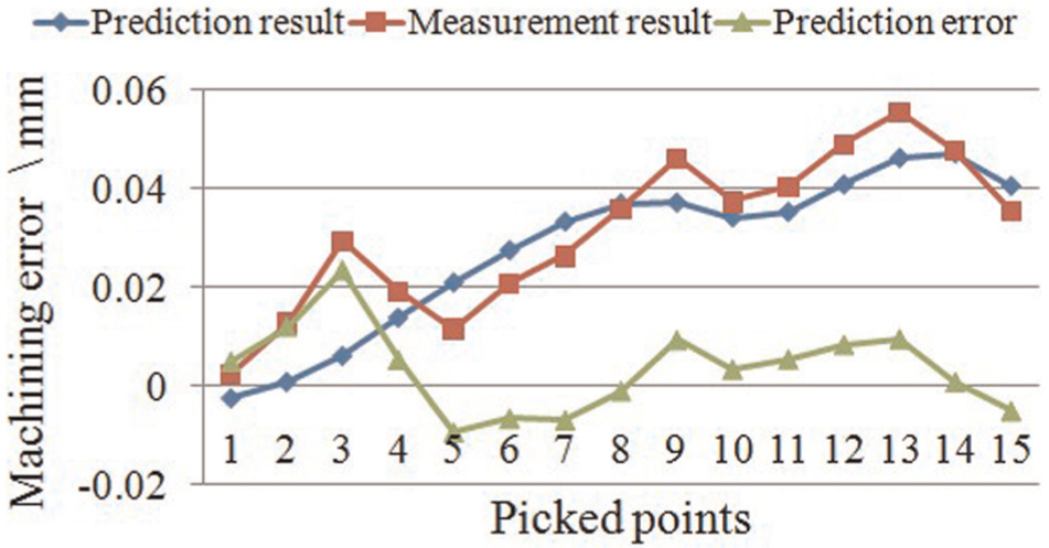
Machining error prediction and measurement results.
In the prediction, machine tool geometric error, workpiece locating error, tool dimension error and setup error were measured. But other error sources such as deformation, thermal error, tracking error and so on were not included. To reduce the effect by these errors, the cutting parameters were selected safely and the machine tool was preheated in the cutting process.
From Figure 13, it can be seen clearly that the predicted machining errors are close to the measured ones. The mean error (ME) is 0.0035 mm and the root mean square error (RMSE) is 0.0090 mm. Obviously, the error curves in Figure 13 show that the proposed model can predict the machining error to a large degree. And it is shown that the proposed method is correct and feasible.
Conclusion
The feasibility of MBS and HTM used for machine tool geometric error modeling has been proven in the previous researches.6–10 In this study, an error synthesis model is established for five-axis peripheral milling based on MBS and HTM, which integrates machine tool geometric error, workpiece locating error, cutting tool dimension error and setup error. By the synthesis model, the machining error of any cutting position can be predicted as measured by CMM, which can be further used for dimension error and form error prediction, even error compensation and process optimization.
The proposed model has been implemented into a prototype software system. The error parameters are identified and stored in a database. A cutting test was carried out to test the practicability and effectiveness of the proposed method. To reduce the effect by other error sources, the cutting parameters were selected safely and the machine tool was preheated. The result shows consistent trend of the predicted and measured machining errors (Figure 13). It can be seen that the proposed model can predict the machining error to a large degree.
Further researches containing more error sources will be conducted in the future.
Footnotes
Appendix 1
Appendix 2
Declaration of conflicting interests
The authors declare that there is no conflict of interest.
Funding
This work is supported by (1) the Special Fund of High-end CNC Machine Tools and Basic Manufacturing Equipment (2010ZX04015-011), (2) Sichuan Applied Basic Research Plan (2012JY0092) and (3) the Fund of New Century Excellent Talents (09-0665) in China.