
Abstract
The purpose of this study is to minimize pocketing time by exploiting the most beneficial aspects of tool dynamics and the most beneficial chronology of tool passes in contour-parallel toolpath. This is achieved by always prescribing limiting axial and radial depth pairs on a contour-parallel toolpath as a means of minimizing pocketing time within milling machine load specifications. The optimization approach is identified to be of two types: boundary to centre (b→c) execution and centre to boundary (c→b) execution. Expression for pocketing time is developed for each type taking into account the revelation that the lengths of the bivariately optimized cyclic passes between the first and last cycles constitute an arithmetic series. The presented expressions are demonstrated to be useful in systematic determination of choice of progression (either (b→c) execution or (c→b) execution) of contour-parallel pocketing operation and choice of limiting axial and radial depth pairs that guarantee minimum machining time. For example, the studied experimentally characterized case gave that (c→b) execution is more time saving than (b→c) execution by about 3.5565%–15.7690%. This experimentally characterized case also confirms the expectation that continuous tool–workpiece contact of contour-parallel toolpath always ensures a shorter pocketing time than both one-way up- and down-milling toolpaths. It is further seen that it is faster pocketing at high radial depth range of 60%–100% of tool diameter which fortunately is the range of less load restrictions. The benefits of contour-parallel toolpath relative to one-way up- and down-milling toolpaths got more strongly confirmed when the pocket got larger (for example, the time saving of (c→b) execution relative to one-way up-milling attained 51.6733% for a larger pocket, while time saving of 41.3385% was recorded for smaller pocket) and when the slope of limiting radial depth versus axial depth got less.
Introduction
The most violent self-excited vibration in machining operation is called regenerative chatter or secondary chatter. Other less frequently occurring thus less studied self-excited vibrations in machining operations are classified as primary chatter which are further divided into mode coupling effects, 1 frictional effects and thermo-mechanical effects. 2 From the inception of machining processing of materials, it has been in the mind of engineers and machinist to control vibrations which limit productivity, incur loss and result in poorly performing parts. This could be why at the beginning of the 20th century Taylor described it as the most obscure and delicate of all problems facing the machinist. In the absence of theoretical knowledge, chatter control began with trial and error method based on experience and manuals. Systematic control of regenerative chatter began with discovery of its delayed nature and subsequent modelling of orthogonal turning process with autonomous delay differential equation (DDE). This happened during the later part of the sixth decade and early part of the seventh decade of the twentieth century as seen in the work of Tlusty et al. 1 Analysis led to computation of stability lobes that demarcate the cutting process parameter plane into stable and unstable sub-domains allowing systematic choices of non-chattered productive parameter combinations. Regenerative chatter is basically triggered by unstable cutting force variation that stem from unfavourable phase difference between two adjacent cuts. The basic milling process was subsequently modelled with linear periodic single discrete DDE by Sridhar et al. 3 The non-autonomous nature of milling model required much more challenging stability analysis than what obtained in turning process and a number of methods were developed to surmount the problem. Some of the methods are as follows: frequency methods which include the zeroth-order approximation (ZOA) method (so-called because it utilizes only the first term in the Fourier series expansion of periodic coefficients) 4 and the multi-frequency solution (MFS) method (so-called because it utilizes higher order harmonics), 5 the semi-discretization methods (they basically entail regular partitioning of the delayed term while leaving the undelayed terms unpartitioned and approximating the periodic coefficient matrices as piecewise constant functions leading to construction of time-domain finite-dimensional monodromy matrix from which stability conditions are extracted via eigenvalue analysis), 6 the methods of temporal finite element analysis (they are based on integral minimization of weighted residuals and accordingly 7 h-version and P-version exist for general periodic single discrete delayed system), the Chebyshev collocation method (it utilizes the collocation expansion at the Chebyshev collocation points) 8 and the full-discretization methods (like the semi-discretization methods, the delayed state in these methods is regularly discretized in addition to discretization of the current state).9–11 A simple experimental equivalent of the above-mentioned analytical methods was proposed by Quintana et al. 12 Their method involves tool–workpiece arrangement that guarantees rising axial depth in feed direction such that a point on milling stability diagram initiates chatter.
During the development of the above listed methods, chatter-suppressing passive and active effects were being introduced in the basic milling model. The effects led to more advanced but somewhat more stable models. The passive dampers do not require external supply of energy to suppress vibration. They include geometric alteration of the tool to interfere with regenerative effects, improved design of machine tool structure against vibration or incorporation of extra devices with good material damping properties for energy dissipation. Some of the known chatter-suppressing geometric alterations of the tool include the following: milling tools with non-uniform pitch thus having multiple discrete delays, 13 variable helix tools 13 and serration of milling tools. 14 Some alterations in tool geometry such as tool wear, edge radii and flank angles/profiles suppress chatter by process damping at low speeds. 15 A chatter-suppressing passive device has been suggested by Semercigil and Chen. 16 A suggestion by Kim et al. 17 involves introduction of frictional damping material into a cylindrical hole drilled in the centre of end-milling cutter to dissipate chatter energy. The active dampers on the other hand require external supply of energy to limit vibration within a range. Generally active vibration controllers are servomechanisms of electromechanical, electro-fluidic, electromagnetic or piezoelectric types that are composed of the major elements: sensor, signal processor and actuator. Active control of chatter with novel electromagnetic proof-mass actuator was presented by Huyanan and Sims. 18 Chatter in milling has been suppressed by Brecher et al. 19 by bringing into a milling machine a piezoelectric-actuated workpiece holder. Other active techniques like spindle speed variation (SSV) work by disrupting regenerative effects. Elaborate work which includes the study by Bediaga et al. 20 has been carried out focussing on SSV as a means of chatter control. SSV is more effective at low speed but Seguy et al. 21 have shown that it more effectively suppresses high-speed flip bifurcation than Hopf bifurcation at the first lobe.
The pursuit of more complicated mathematical models for the mentioned stabilizing designs does not mean that the dynamics of the basic model has been fully exploited. The stabilizing designs are unconventional and unpopular thus requiring costly and probably unworthy awareness creation for widespread adoption. The gains are sometimes not considerable enough to galvanize a paradigm shift in the manufacturing industry. Such stabilizing designs do not come without additional technological demand or even dynamic problems like inertia problems in SSV. Worse still, the computed benefits could fall in a technological range that is not preferred for a machine tool in question. Several efforts have been made to make the most of the dynamics of the basic milling model in planning for productive and smooth milling project. Tekeli and Budak
22
optimized material removal rate (MRR) of pocketing process with limiting pairs of axial depth of cut and radial depth of cut. Heo et al.
23
considered stability limit of the basic milling model in addition to load capacity of the spindle as a constraint in their formulation and evolutionary analysis of time of high-speed pocketing. Ozoegwu and Ezugwu
24
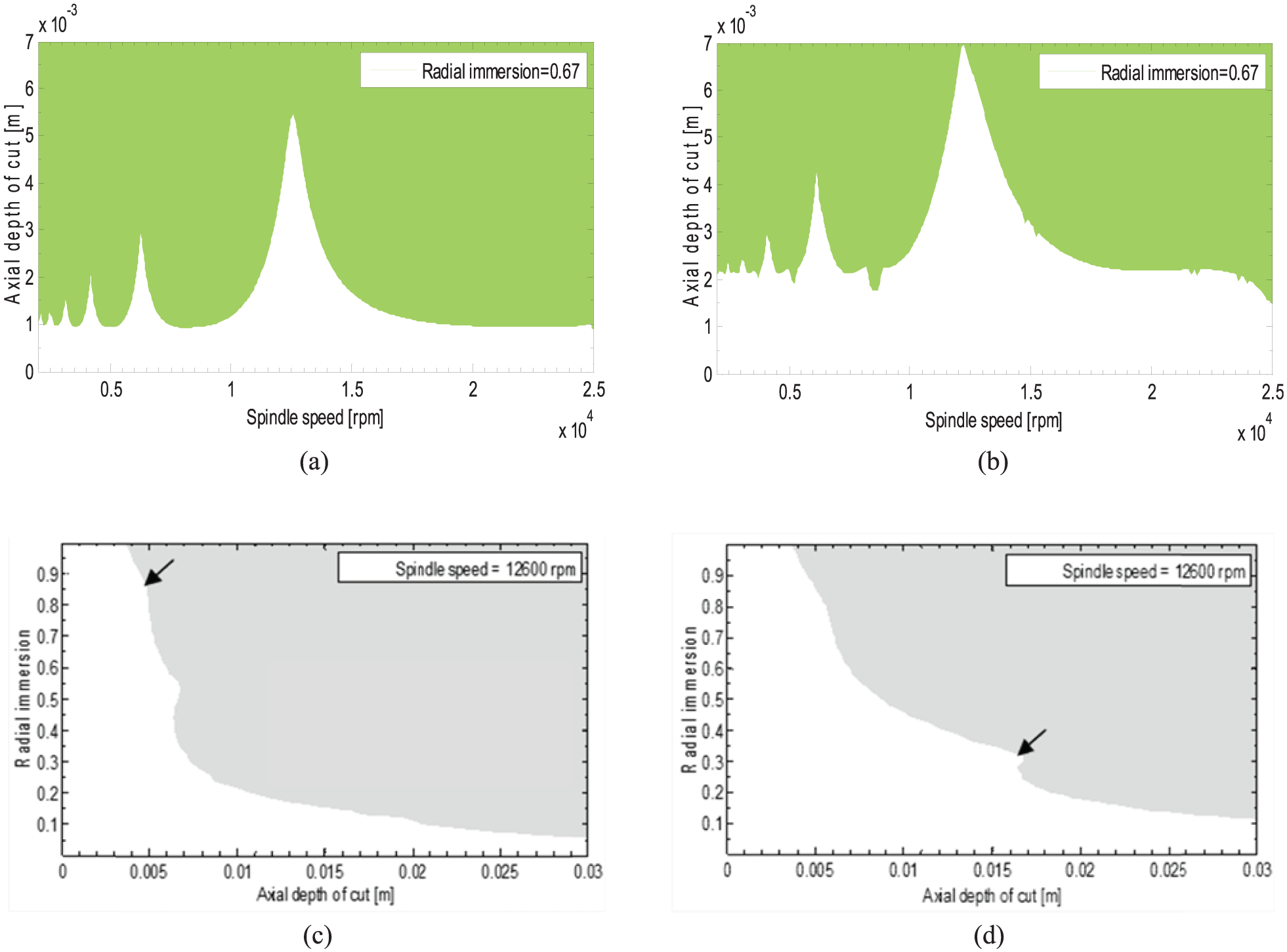
further explored and generalized the optimization strategy of Tekeli and Budak leading to identification and comparison of two alternative pocket execution routines: vertical chronology (VC) and horizontal chronology (HC). They saw that the former is superior in saving time. Existence of a coordinate for maximum limiting MRR (
Model and stability analysis of milling process
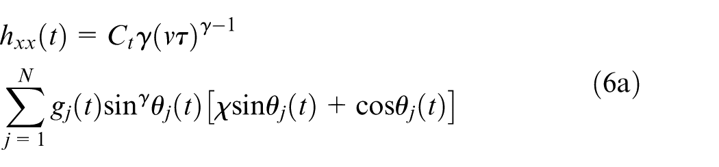
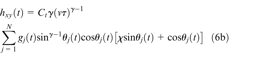
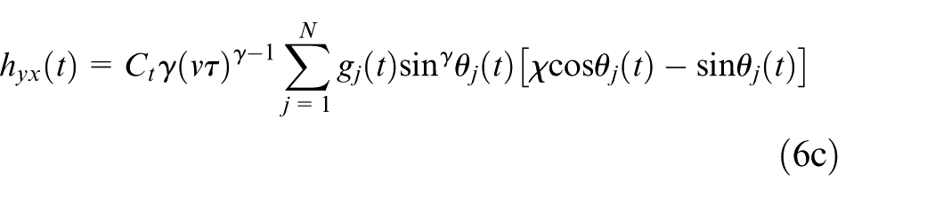
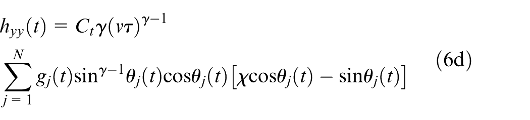
A 2-degree-of-freedom (2-DOF) milling model is used because of tool compliance in both feed and feed-normal directions. The model for analysis with the full-discretization method is put in the form

where
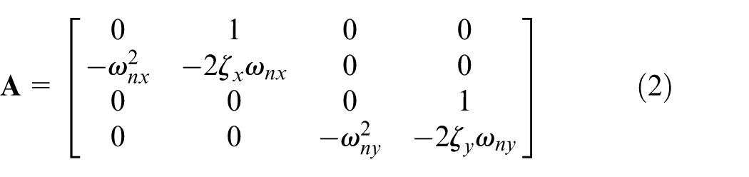
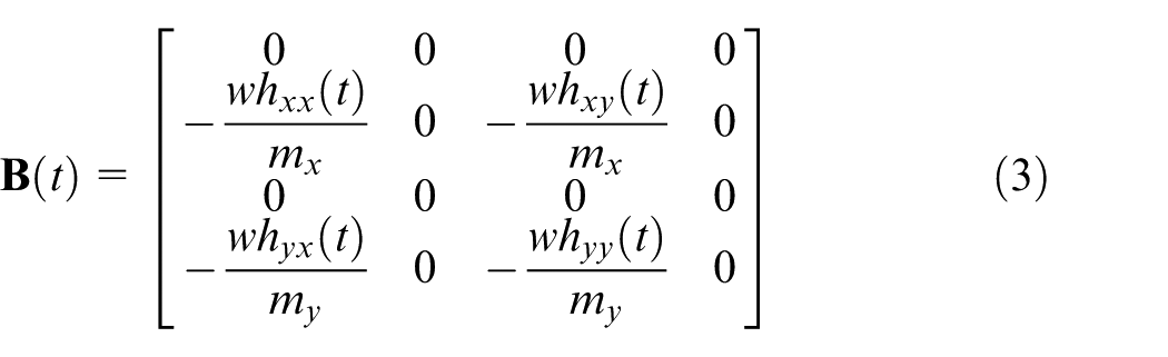
The modal parameters with subscript (x) refer to the feed direction, while those with subscript (y) refer to the feed-normal direction. The w is the axial depth of cut. The radial immersion which is the non-dimensionalized radial depth is contained in the model via the screen functions
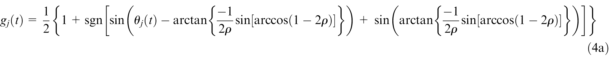

The angular position of jth tooth
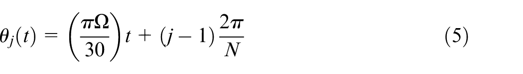
This means that the spindle speed
All the coordinates involved in the derivation of the milling model presented above rotates 90° with the feed when the tool on a contour-parallel toolpath moves from one edge to a perpendicular edge. The direction of modal parameters remains fixed so that orthogonal change in feed direction is taken care of by interchange of
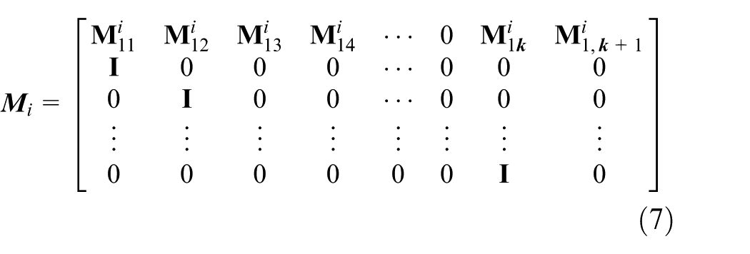
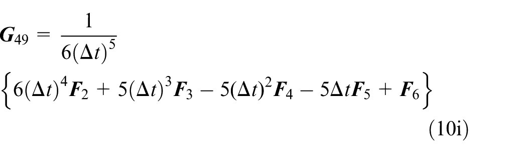
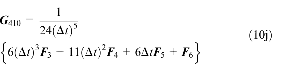
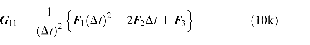
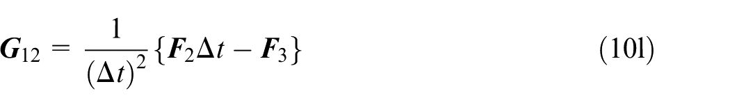
The fourth-order full-discretization method
11
is adopted here for stability analysis because of its accuracy. The monodromy matrix reads


By tracking the parameter combinations that ensure existence of the spectral radii of the monodromy matrix on the circumference of the unit circle, the stability limit that demarcates the stable and unstable spaces is determined. The process of tracking these critical parameter combinations on the plane of axial and radial depths is given as detailed flowchart in Ozoegwu et al. 25
Analysis of time of contour-parallel pocketing with limiting depths pairs
The combination of prescription parameters such as feed speed, axial depth of cut, radial depth of cut and geometric restrictions of the pocket, the tool and the toolpath influences pocketing time by influencing the distribution of MRR of active tool passes towards creation of the pocket.
24
Rectangular pockets of dimensions length
Execution from the pocket boundary to centre
Suppose the contour-parallel VCs are concentric from the pocket boundary to the pocket centre, then analysis of machining time becomes as follows. The VCs are numbered 1, 2, 3, … from the pocket boundary to the last VC at the centre of the pocket. The length of each cycle of pass on nth VC is

where
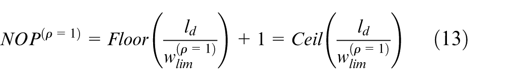
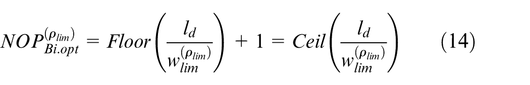
The number of cyclic passes needed to complete each of the bivariately optimized VCs lying between the first and last (central) VCs is given as
The total travel distance for executing the first VC is
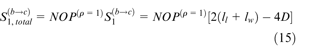
where
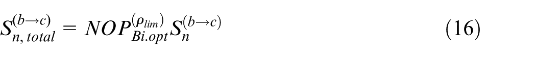
The overall distance travelled by the tooth executing all the bivariately optimized VCs lying between the first and last VCs is given by
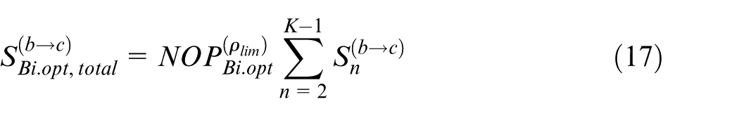
where K is a value that depends on which of the conditions
which becomes
When the condition
Depicting the geometric situation of the first and last VCs of contour-parallel pocketing from boundary to centre when (a)
The inequality (
where

The total length for executing the last VC is
The machining time becomes
When the condition
The length of cycle of pass of the last VC is
where
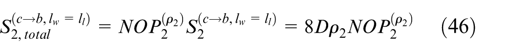
The total length for executing the last VC is
The machining time becomes
When the condition
The length of cycle of pass of the last VC is
where

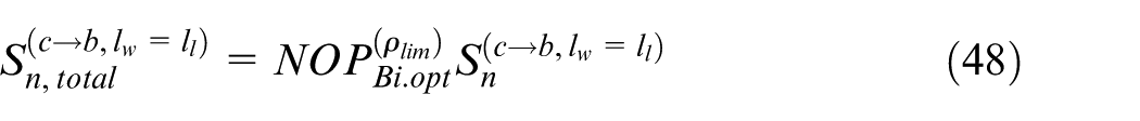
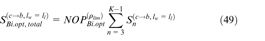
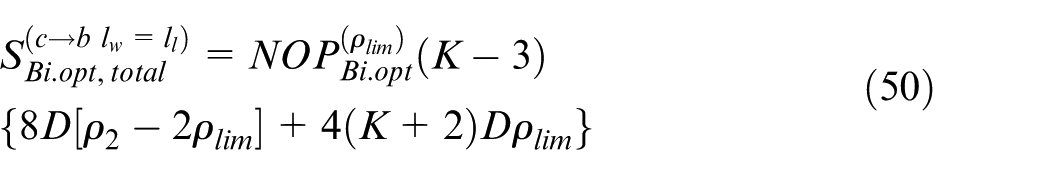
The total length for executing the last VC is
The machining time becomes

Execution from the pocket centre to boundary
Suppose the contour-parallel VCs are concentric from the pocket centre to the boundary, then analysis of machining time becomes as follows
Suppose
Depicting the geometric situation of the first and last VCs of contour-parallel pocketing from centre to boundary when (a)
The number of passes needed to complete each of the bivariately optimized VCs lying between the first (central) and last (boundary) VCs is still given by equation (14). The length of each cycle of pass on nth VC is

where
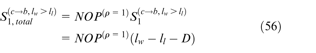
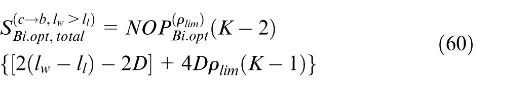
The overall distance travelled by the tooth executing all the bivariately optimized VCs lying between the first and last VCs is given by
where
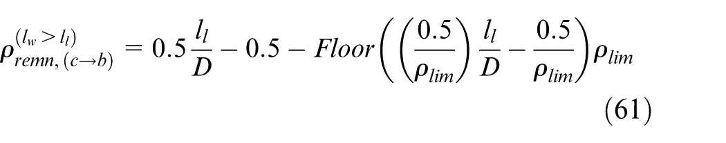
The remnant radial immersion for execution of the last (boundary) VC becomes

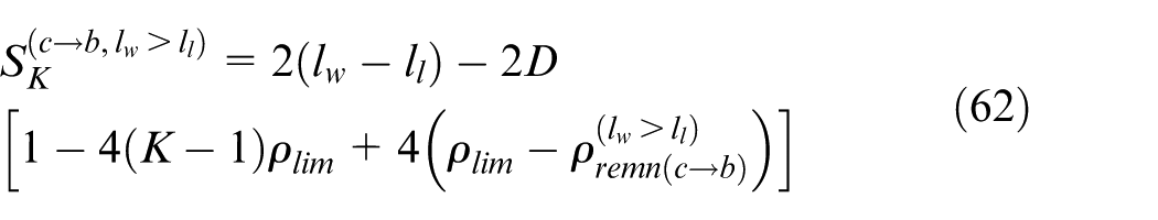
The length of a cycle of pass of the last VC is
The axial depth of cut corresponding to

The total length for executing the last VC is
The machining time becomes
Suppose
The total length for executing the second VC is
Each of the VCs lying between the second and last VCs is bivariately optimized at

where
The overall distance travelled by the tooth while executing all the bivariately optimized VCs lying between the second and last VCs is given by
where
The remnant radial immersion for execution of the last (boundary) VC becomes
The length of a cycle of pass of the last VC is
The axial depth of cut corresponding to

The total length for executing the last VC is
The machining time becomes
Suppose
The number of cyclic passes needed to complete each of the bivariately optimized VCs lying between the first (central) and last (boundary) VCs is still given by equation (14). The length of each cycle of pass on nth VC is

where

The overall distance travelled by the tooth executing all the bivariately optimized VCs lying between the first and last VCs is given by

where
The remnant radial immersion for execution of the last (boundary) VC becomes
The length of a cycle of pass of the last VC is
The axial depth of cut corresponding to

The total length for executing the last VC is
The machining time becomes
Numerical computations and discussions
The expressions for machining time presented in the section ‘Analysis of time of contour-parallel pocketing with limiting depths pairs’ are expected to be useful in systematic determination of choice of progression (either boundary to centre
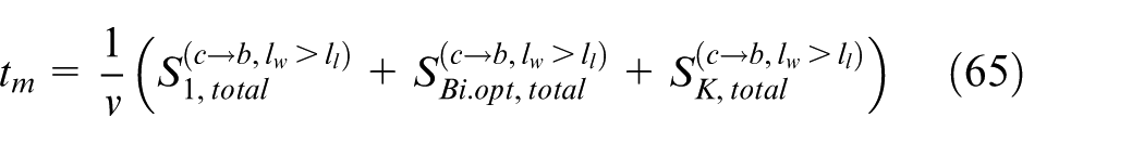
(a) The stability limits of 2-DOF up-milling of
(a) The stability limits of 2-DOF up-milling for x-feed direction at 12,600 r/min on
Numerical analysis of machining time requires numerical choice of
Pocketing time optimization employing contour-parallel VC with
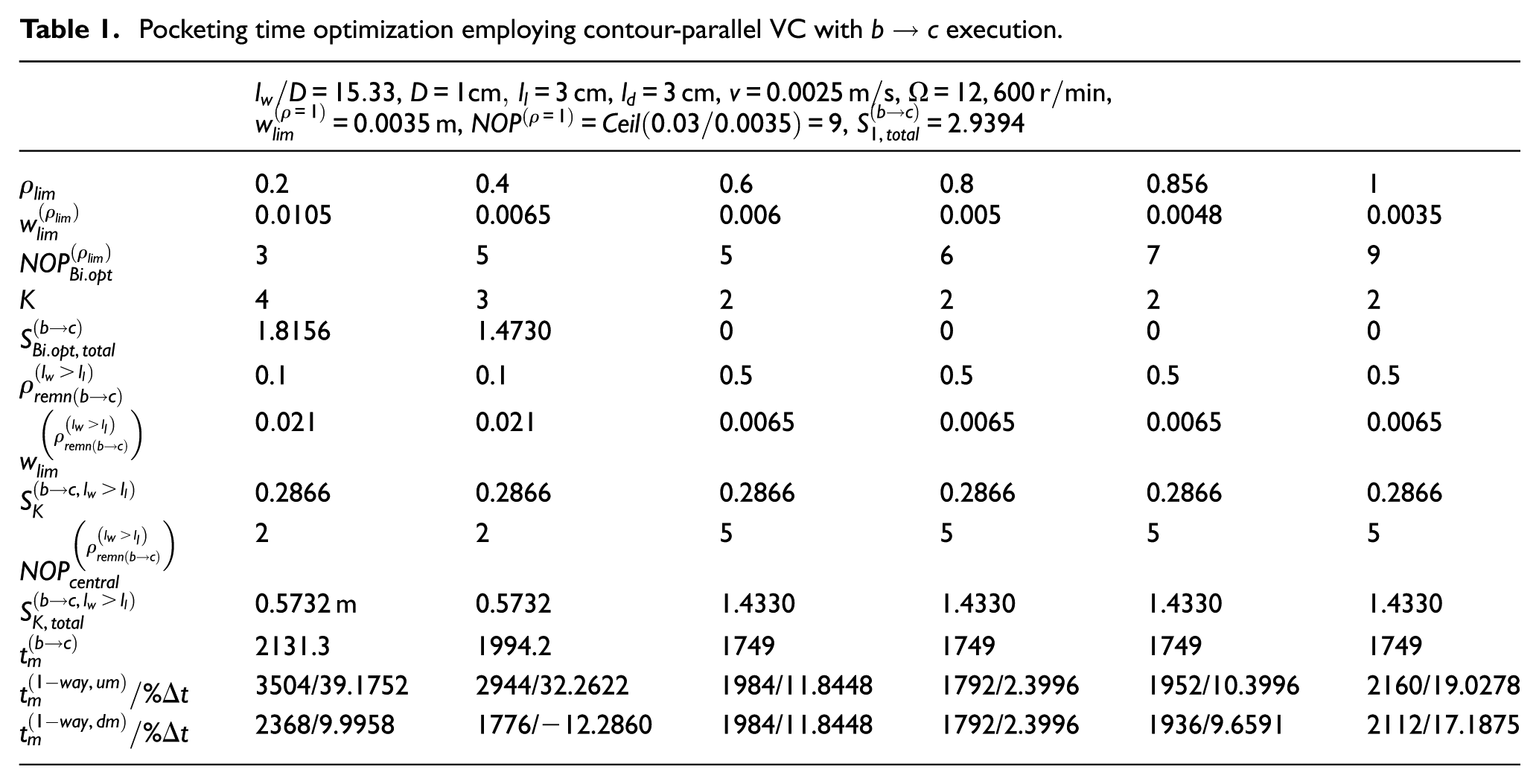
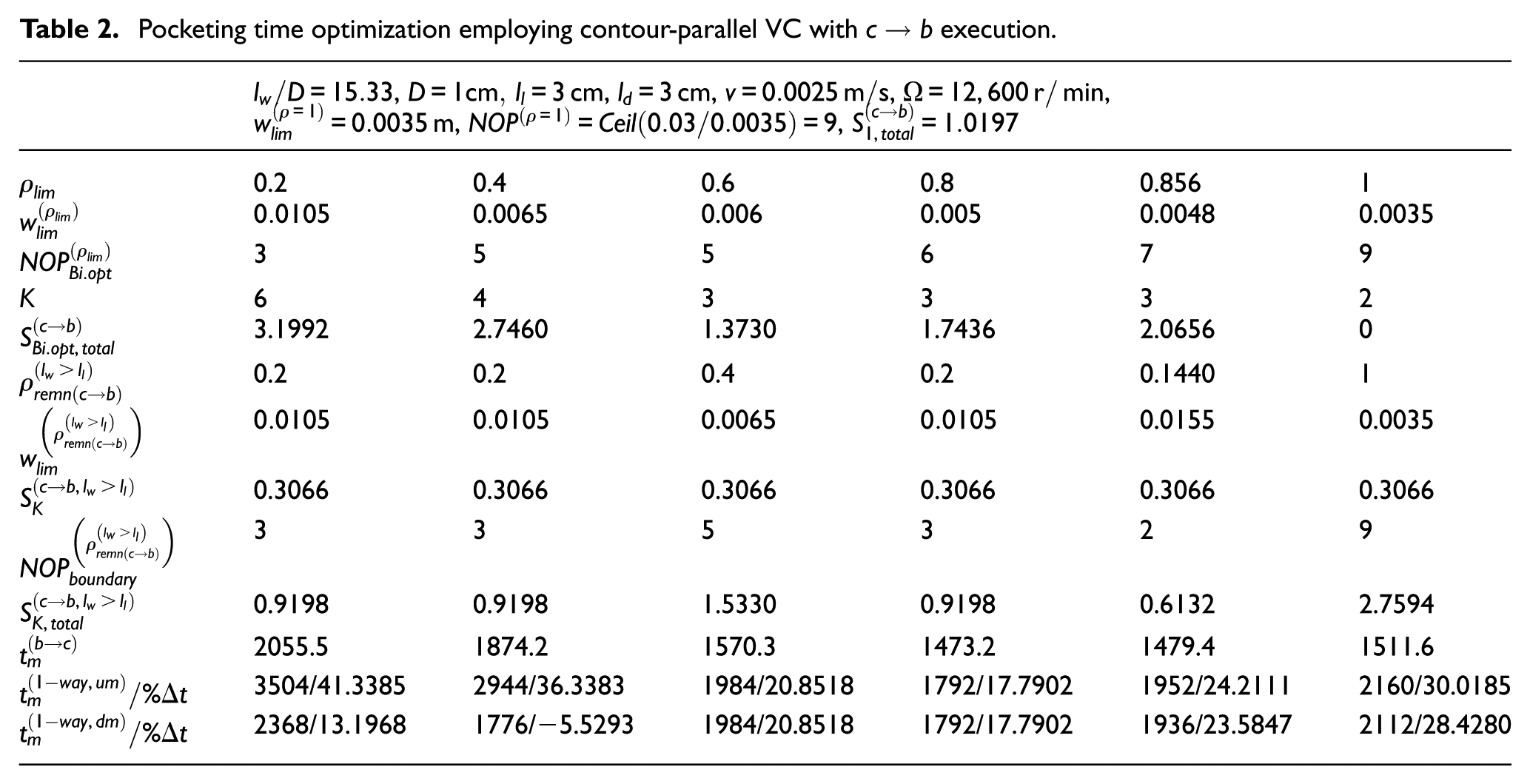
The studied case,
Pocketing time optimization employing contour-parallel VC with
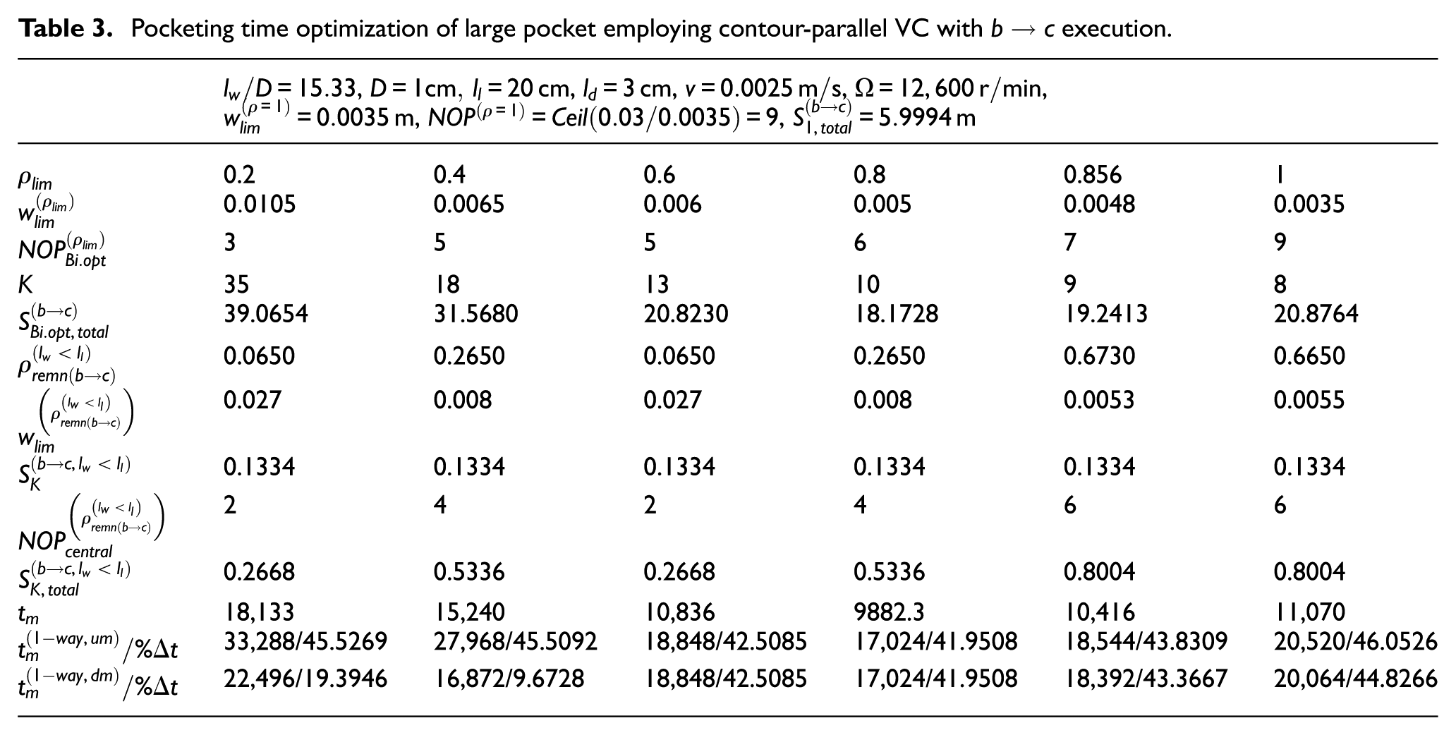
Suppose a lengthier pocket with
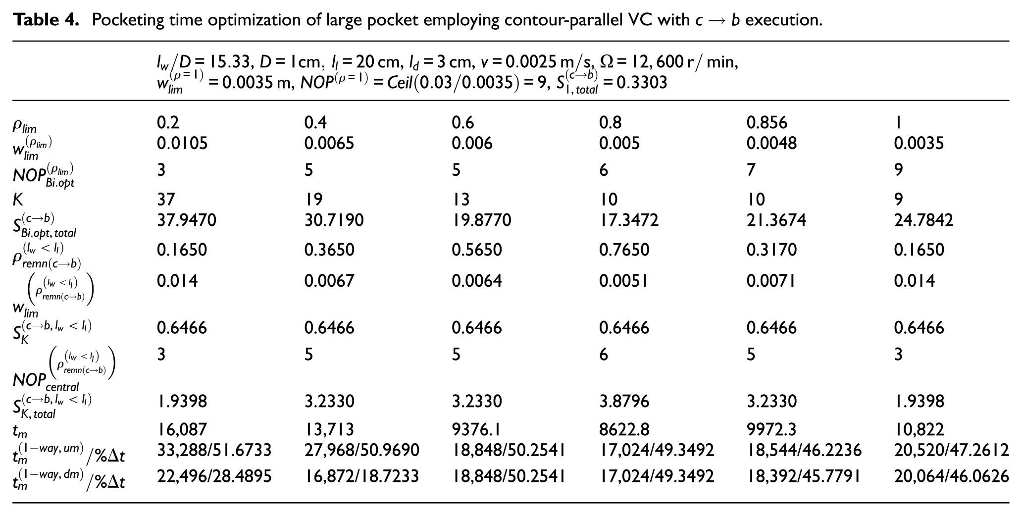
Pocketing time optimization of large pocket employing contour-parallel VC with
Pocketing time optimization of large pocket employing contour-parallel VC with
Conclusion
Optimization of contour-parallel toolpath with limiting axial and radial depth pairs is investigated in this work as a means of minimizing pocketing time within milling machine load specifications. This optimization approach is identified to be of two types: boundary to centre
Footnotes
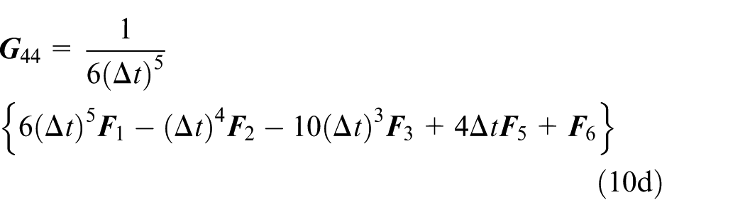
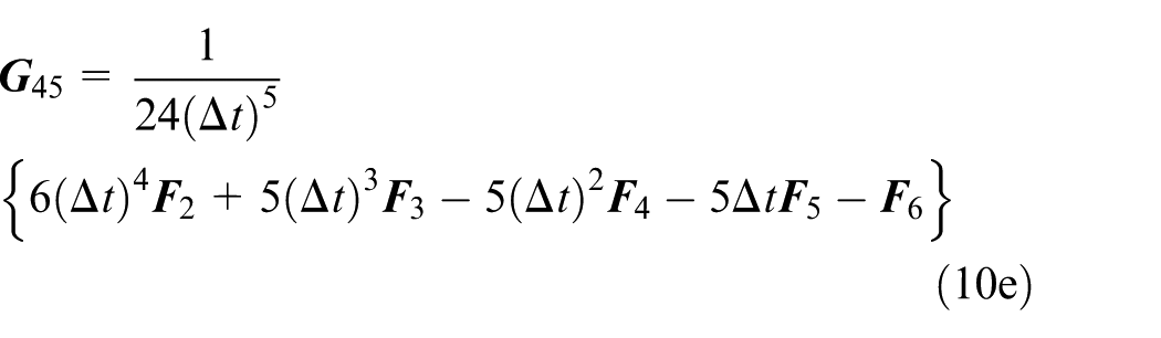
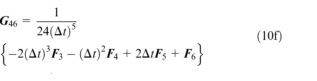
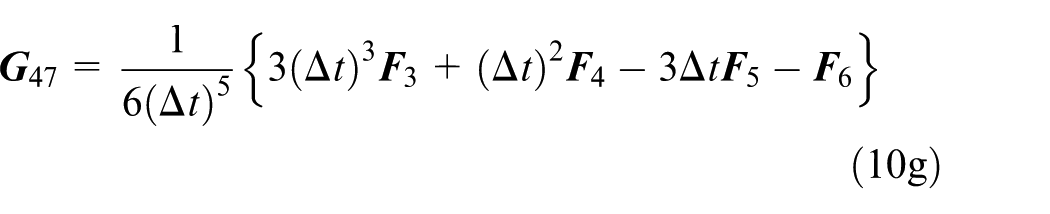
Appendix 1
Acknowledgements
I appreciate the policies of the University of Nigeria that emphasize novelty and innovation in research.
Declaration of conflicting interests
The author(s) declared no potential conflicts of interest with respect to the research, authorship and/or publication of this article.
Funding
The author(s) received no financial support for the research, authorship and/or publication of this article.