
Abstract
In this paper, the manufacturing challenges and related technological solutions concerning the prototyping of microwave ablation (MWA) probes are addressed. In particular, the intertwined aspects pertaining probe design, fabrication and target performance are tackled. The development of a 14G MWA probe prototype, working at a frequency of 2.45 GHz, is proposed as a case study, describing design efforts and the use of rapid prototyping technologies combined with other manufacturing processes. A specific focus is dedicated to the insulating part of the probe radiating section, featuring high aspect ratio and complex shape, which was fabricated by means of Digital Light Processing (DLP) and by using a biocompatible material, the EnvisionTEC E-Shell® 300. Furthermore, the probe handling, properly designed to arrange cables and tubes routing, was fabricated by means of Fused Deposition Modeling (FDM) technology. Finally, ex vivo experiments conducted on bovine liver showed satisfactory treatment performance and structural reliability of the 14G MWA probe prototype. Besides being characterized by a good impedance matching (S11 = −25 dB), prototype performance were also in good agreement with design simulations and even satisfying if compared to other results available in literature as, with an input radiation power of 40 W, the ablated zone after a 10 min treatment exhibited a ratio of the radial and longitudinal axis of 0.66.
Keywords
Introduction
In 2019, cancer still held as one of the leading causes of mortality worldwide. 1 In the last decades, minimally invasive tumor treatments based on hyperthermia have been proposed and practiced, proving their effectiveness toward complete patient healing, especially in the case of early detection. Hyperthermia treatments rely on different technologies, such as laser, radiofrequency (RF) and microwave (MW). In general, the base principle of these techniques relies on the induced temperature increase of the tumor area, causing the destruction of the tumor cells. This is achieved by inserting one or more thin needle-like probes into the target area of the organ affected by the tumor, minimizing surgical wounds and, thus, aiming at minimal invasiveness.
The maximum temperature accomplished during the treatments represents an important parameter characterizing hyperthermia techniques as, coarsely, higher temperatures enable shorter surgical treatments. MW ablation (MWA) attracts more and more interest due to its advantages compared to the earlier RF-based approach, such as higher treatment temperature, faster heating, larger active heating zone, reduced susceptibility and distortion of the ablated area when the treatment is carried out close to large vasculature zones.2,3
A MWA system is generally composed of a microwave generator and an applicator (probe), technically acting as an antenna. The probe is the most delicate part of the whole system, as it has to comply with the minimal invasiveness requirement. For this reason, the probe is characterized by a small diameter size (typically spanning from 17 to 11G, about 1.40 ÷ 3.00 mm) and a length sufficient to reach the internal zones subjected to the ablation. Moreover, the probe dimensions are also linked to the operation frequency of the MW signal, propagating into the probe via an inner coaxial cable connected to the MW generator output. Usually, two frequencies are considered, 0.915 or 2.45 GHz, as these values are regulated by the Industrial, Scientific and Medical (ISM) standardization 4 and are used by the current commercial MWA systems. Some performance indicators characterize a MWA treatment, in particular from the perspective of minimal invasiveness: the “sphericity” of the ablated area, referred hereon also as “axial ratio” and defined as the ratio of the radial and longitudinal axis of the ablated area (Figure 1), the temperature profile, which must be isothermal with respect to normal tissue one along the shaft, and reduced treatment times (usually, around 10–15 min).
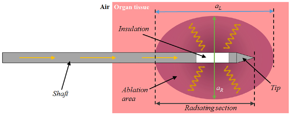
Schematic of a MW ablation probe. aL and aR represent the longitudinal and radial axis of the ablation volume, respectively.
The scientific community is currently investigating the performance of commercially available products. In particular, it has been observed in Farina et al. 5 that the use of different commercial MWA devices leads to significantly different results in terms of non-uniform shrinkage within the coagulated area. Similar considerations have also been reported in Tammam et al. 6 and Mohtashami et al., 7 showing that different applicators, based on various coaxial antenna designs, provided ablated areas displaying diverse axial ratios, strictly related to the rate of MW backward radiation. In a recent review, 8 a new generation of devices was compared to traditional ones, exhibiting the peculiarity of accomplishing spherical ablation of the treated tumor cell in hepatocellular carcinoma, also feasible for highly vascularized zones.
Aiming at improving ablation performance, plenty of MWA probe designs for the treatment of breast, liver, lung, and kidney tumors are proposed in literature. 9 In particular, a recent article 10 reviewed the most reliable antenna designs pertaining MWA probe developed so far, with the aim of identifying the most efficient ones in terms of expected ablation area distribution, high MW power transmission and minimal invasiveness. To this aim, three basic antenna types were acknowledged: monopole antenna with choke, dipole antenna with sleeves and slot antenna with double choke. Alternatively, pioneering works are also proposed in literature, concerning MWA applicators characterized by exotic concept designs11,12 solutions comprising non-coaxial antennas, 13 dual mode, 14 and higher frequencies operation. 15 Regarding this latter aspect, numerical analyses and experiments demonstrated that an axial ratio almost equal to 1 could actually be accomplished by increasing the operational frequency (from 2.45 up to 18 GHz). Additionally, a further aid toward the shape and dimensional control of the ablated area may be provided by the use of a cooling fluid, as proved by the results reported in Kuang et al., 16 Wang et al., 17 Zhou et al., 18 Leapman et al., 19 Horn et al., 20 Ziemlewicz et al., 21 and Fallahi et al. 22 Actually, the presence of the cooling systems is generally advisable to cope with the probe overheating, as the temperature increase along with the probe length may induce damage to normal tissues surrounding the applicator and spoil the whole system reliability. Nonetheless, the addition of cooling channels has an impact on the probe size; therefore, the device integrated design requires a considerable effort.
The aforementioned studies highlighted that all design solutions are aimed mainly at the achieving minimal invasiveness and increasing the axial ratio, obtained through the control of the ablated area shape. However, these performance targets have relevant consequences on the MWA probe fabrication complexity. In particular, hosting additional components, such as the cooling system, as well as the use of specific materials, such as thermally insulating and bio-compatible ones, furtherly compounds the design of thinner and thinner probes. Nonetheless, despite the evident interlinks between MWA probe design, fabrication and assembly, becoming even more relevant aiming at device optimization, the mutual impact that all these aspects have on each other is not addressed by the recent literature.
Therefore, this paper addresses the fabrication challenges pertaining the prototyping of a MWA probe, while considering the final expected performance; in order to comprehensively outline the context, the main steps pertaining to the design prototyping of such a device are presented. The discussion builds on a case study regarding the 14G MWA probe, whose design was presented in Portosi et al.23,24 In these papers, all details related to the antenna electromagnetic design and optimization have been outlined. Hence, in the present work, the fabrication challenges related to the mechanical design of the 14G MWA probe are disclosed and technologic solutions are proposed. In this viewpoint, as a MWA probe is characterized by a very short life-cycle, the use of consumer additive manufacturing (AM) options is also highlighted.
In general, effective product development is a critical issue in the field of medical devices, in which the optimal integration of medical and engineering competences are essential the whole cycle (design, prototyping, and manufacturing). 25 The increasing widespread use of AM techniques for the fabrication of medical instruments plays an important role to enable, besides lower prototyping times, more complex designs, cost savings – which can be also quantified and compared 26 – and higher degree of patient-oriented customization.27,28 In this paper, the use of two different AM technologies is proposed for the MWA probe prototyping: Fused Deposition Modeling (FDM) to realize the handling case and Digital Light Processing (DLP) for the fabrication of an inner insulating component, characterized by demanding geometric features and high aspect ratio. The former is acknowledged as one of the most widespread 3D printing technique, whose performance can be significantly increased by process parameter optimization,29,30 while the latter is based on the stereolithography principle, which is more suitable for manufacturing parts displaying demanding features at the microscale.31–34
The paper is organized as follows: a description of the probe architecture and typical performance targets is reported in section “MWA probe architecture and performance targets”; section “Approach for prototype development” illustrates the approach used for the development of the MWA probe prototype. The MWA probe design is then detailed considering the 14G case study (section “MWA probe design and prototyping”); concerning in particular probe manufacturing, smart solutions are proposed for rapid prototyping, also proposing the use of novel materials and AM technologies. Finally, section “Prototype testing” reports the results and discussion of the ex vivo experiments conducted on a bovine liver, aimed at assessing the performance of the fabricated 14G MWA probe prototype.
Methodology
MWA probe architecture and performance targets
The general scheme of a MWA probe architecture is sketched in Figure 1: the main structural component is an external cylindrical structure – the “shaft”– usually made of biocompatible material (i.e. medical steel) and hosting the inner components, such as the coaxial cable feeding the radiating section. The insertion tip is usually made of conductive material; an insulating component is interposed between the shaft and the tip, thus enabling the reduction of shaft overheating due to the proximity to the ablation target area and the proper emission of MW radiation. The terminal part of the probe, comprising part of the shaft, the insulating component and the tip, represents the actual radiating section. Other inner components can be envisaged depending on the specific probe architecture: a cooling system to further limit shaft heating, chokes or sleeves to improve the MW radiation efficiency.4,6,10,13,15
The effectiveness of a MWA probe is assessed considering the following interrelated targets:
- minimal invasiveness, considering the minimization of surgical wound, shaft overheating, required treatment time;
- the maximization of the axial ratio, related to the controllability of the zone actually targeted by the treatment;
- performance, in terms of antenna impedance matching and minimization of the scattering parameter S11. These two parameters determine the emitted radiation, and thus the ablation temperature (required to be above 100°C), which, in turn, also affects the treatment time.
Table 1 reports the qualitative impact weights that the relevant design features have on these parameters. It is worth observing that descriptors in Table 1 are actually interlinked: the treatment time is reduced when treatment temperature is adequate; the temperature, in turn, depends on the rate of MW power actually transferred to the tissue, and thus on impedance matching and minimization of the S11. Hence, the effect of each indicator on the increase of manufacturing complexity is also reported, highlighting how manufacturing capability is actually a crucial key-enabling factor for an optimized MWA probe. Moreover, this aspect is exacerbated for the fabrication of low-cost devices or small production batches (e.g. a single prototype) due to the effort required for the setup of the production line.
Qualitative impact of design solutions on the manufacturing complexity.
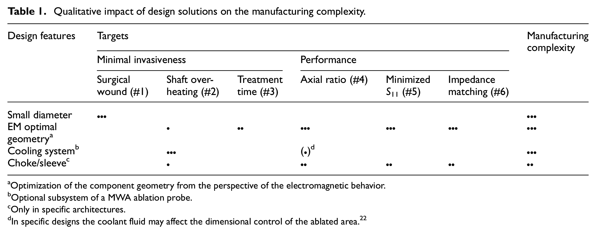
Optimization of the component geometry from the perspective of the electromagnetic behavior.
Optional subsystem of a MWA ablation probe.
Only in specific architectures.
In specific designs the coolant fluid may affect the dimensional control of the ablated area. 22
Approach for prototype development
The aim of targeting minimal invasiveness, axial ratio and performance, while considering the prototyping challenges, has required the implementation of the multidisciplinary approach depicted in Figure 2. Indeed, given a target diameter (i.e. probe gage) as the main constraint, a base architecture was chosen. Subsequently, the probe length was set by considering the position of the internal organ to be reached for the treatment. The length of the radiating section was then assessed through electromagnetic (EM) analyses, as it depends on the evaluation of the scattering parameter S11 and impedance matching. The EM design and simulations were tackled in Portosi et al., 24 and the obtained heat distribution and EM optimal design of the 14G MWA probe were used as the input of the subsequent development steps. The computational fluid-dynamics (CFD) simulations supporting the cooling system design (section “Cooling system design”) are based on the heat distribution and temperature profile retrieved by EM analyses. In this phase, the cooling system was dimensioned by assessing the flow rate needed to meet the interface temperature requirement. The feasibility of the preliminary design of all the components was assessed and finalized in the design for manufacturing and assembly tasks (section “Mechanical design and prototyping”). Once obtained the executive design, the prototyping (section “Mechanical design and prototyping”) and testing (section “Prototype testing”) stages took place. In the present case study, the experiments to verify the device performance were performed ex vivo on a bovine liver.
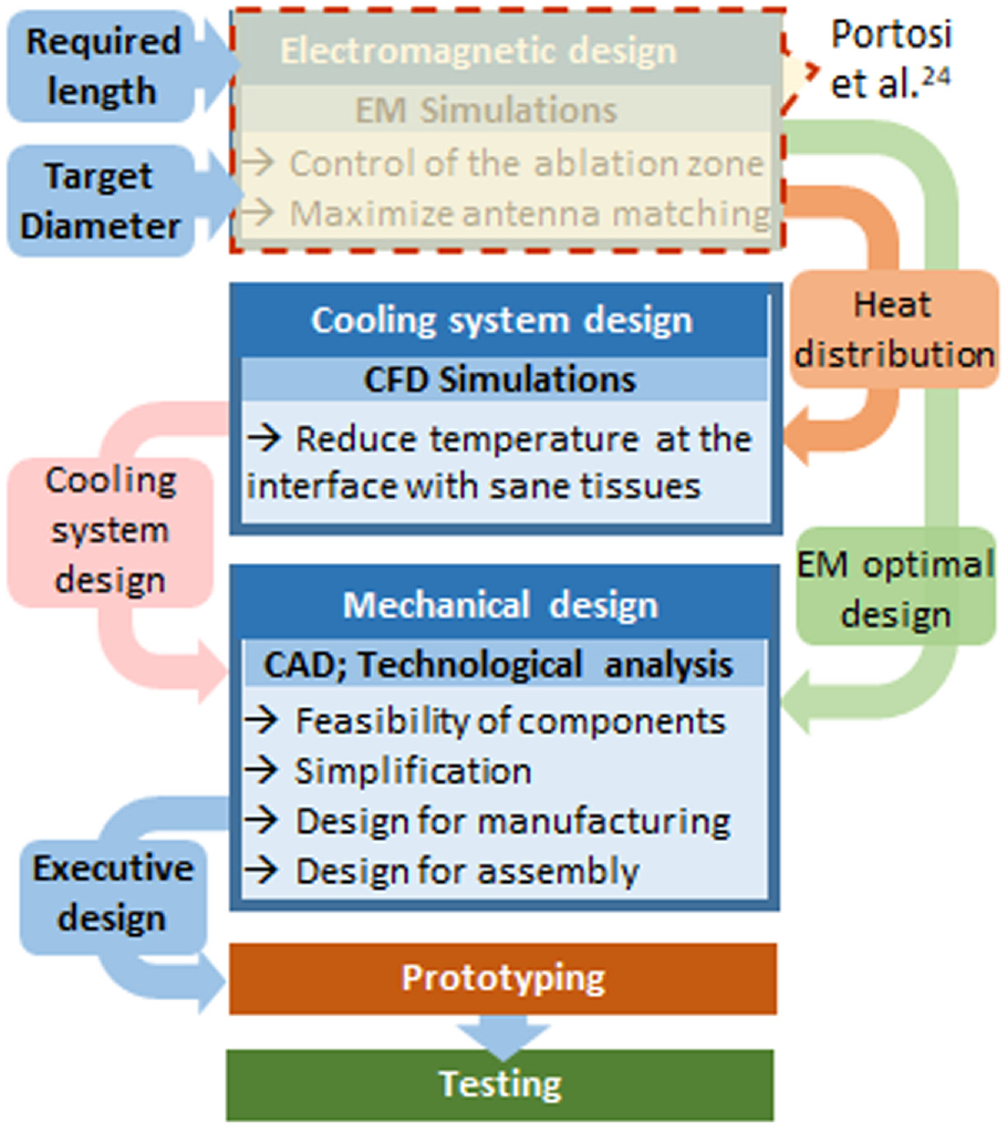
Schematic of the multidisciplinary approach for the prototype development.
MWA probe design and prototyping
The 14G MWA probe object of the study, operating at 2.45 GHz, is based on a choke dipole antenna configuration and is equipped with a liquid-based cooling system. The presence of a choke ensures the electrical continuity between the shaft and the external conductor of the coaxial cable, resulting in the enhancement of the MW field radiation and reduction of the backward currents. Ultra-thin cannulas are used for the transportation of the cooling fluid into the probe. The probe handling is conceived to be externally connected to the MW power source cable and the upstream cooling system flow-channels, with an optimized internal arrangement of tubes and cables.
The geometrical features of the probe were obtained by considering the following main design targets23,24: the minimization of the scattering parameter S11 at 2.45 GHz (target #5 in Table 1), the reduction of treatment time (target #3 in Table 1) and the antenna impedance matching to the biological tissue (target #6 in Table 1). The EM optimization was accomplished by parametric analyses performed by CST Microwave Studio and the final dimensions are detailed in Table 2, with reference to Figure 3.
14G MWA probe: Optimal geometrical parameters. 24
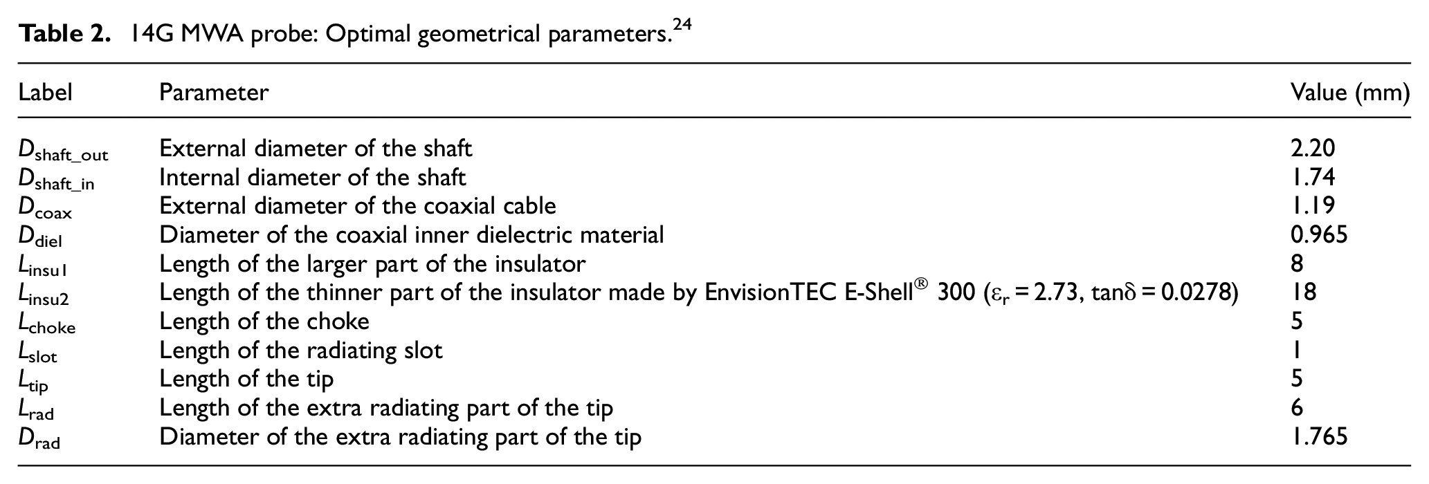
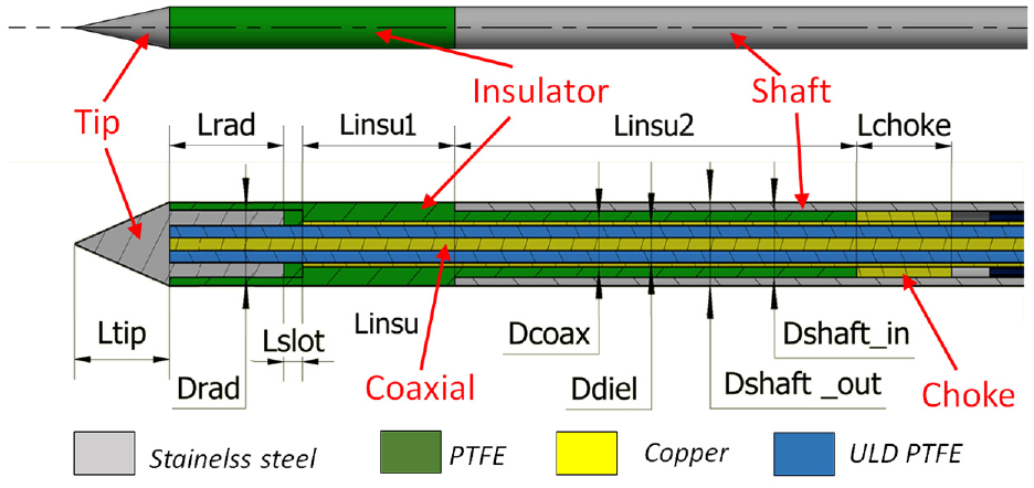
14G MWA probe design. In the transversal section, proportions are specially changed (in particular, vertical dimensions are doubled) in order to highlight all the components.
Cooling system design
The presence of a cooling system prevents the overheating of shaft (target #2 in Table 1) and, thus, of normal tissues surrounding the probe; it can be gas- or liquid-based. 10 In the present work, an open-loop liquid-based system was considered. The liquid (sterilized water) is driven into the MWA probe by an external peristaltic pump: an input circuit, sourced by a liquid bag, feeds the ablation probe and an output circuit enables the drain of the heated fluid.
Considering the reduced space available inside the probe, the design of the cooling system was aimed at identifying the most affordable fabrication solution. Capillary metallic tubes were considered and, in particular, four Ø 0.25 mm stainless steel cannulas are implemented, inserted into the annulus-shaped cavity between the coaxial cable and the shaft. The remaining gap volume is dedicated to fluid drain, forced by the presence of the choke (Figure 4). Such a solution can be considered extremely suitable for manufacturing and assembly purposes, since capillary tubes are commercially available and can be easily inserted into the shaft; furthermore, the use of metallic tubes enables the possibility of soldered jointing solutions.
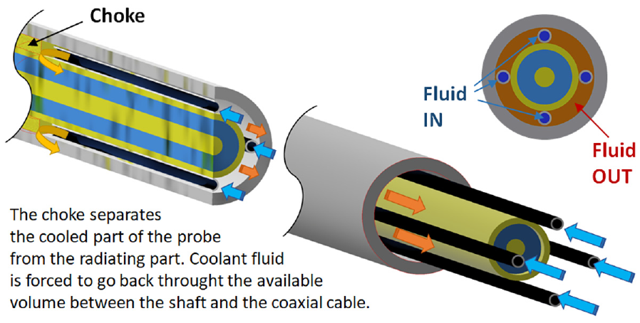
Architecture of the cooling system inside the probe.
The maximum shaft temperature should be kept around 40°C to avoid damaging the adjacent tissues. For the design of the cooling system, several CFD simulations were performed (by using the ANSYS Fluent software), leading to obtaining the best set of parameters, that is, the flowrate and the feeding pressure. The heat distribution retrieved by the electromagnetic analyses was used as input in the CFD simulations; the overheating of the normal tissue was used as target parameter, by controlling the temperature at the probe/tissue interface.
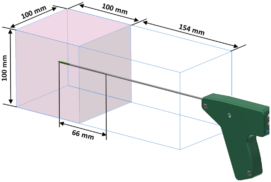
An environment comprising ablation probe and biological tissue was modeled for the simulations (Figure 5). The 220 mm long probe penetrates the tissue up to a depth of 66 mm. The domain outside the probe is a cube with a side of 100 mm, representing the biological tissue, whereas a parallelepiped of 154 mm × 100 mm × 100 mm represents the air. In order to perform the analysis with conjugated heat transfer, an unstructured computational grid (14 × 106 cells) was set, considering the different parts as a single body. The adequacy of the mesh was verified by comparing the pressure drop in the capillary tubes with the value obtained by applying the Hagen-Poiseuille law. A detail of the computational mesh at the inlet section of the four capillary tubes is shown in Figure 6.
Computational domain of the fluid dynamics simulations.
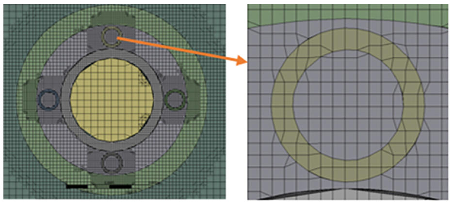
Computational mesh at the inlet of the capillary tubes.
Considering water as cooling liquid, the simulations were performed by testing the following flowrate values: 3.5, 5, and 7.5 ml/min, with a fixed inlet temperature of 5°C. The boundary of the biological tissue was set at a reference starting temperature of 37°C, whereas the air temperature was fixed at 20°C. The thermal flux through the surface of the probe was considered as heat source, whereas the temperature of the tip was set according to the values obtained by the electromagnetic simulations. Regarding the former, the flux profile was conservatively discretized in two constant values, each one corresponding to a different longitudinal portion of the probe, as reported in Figure 7(a).
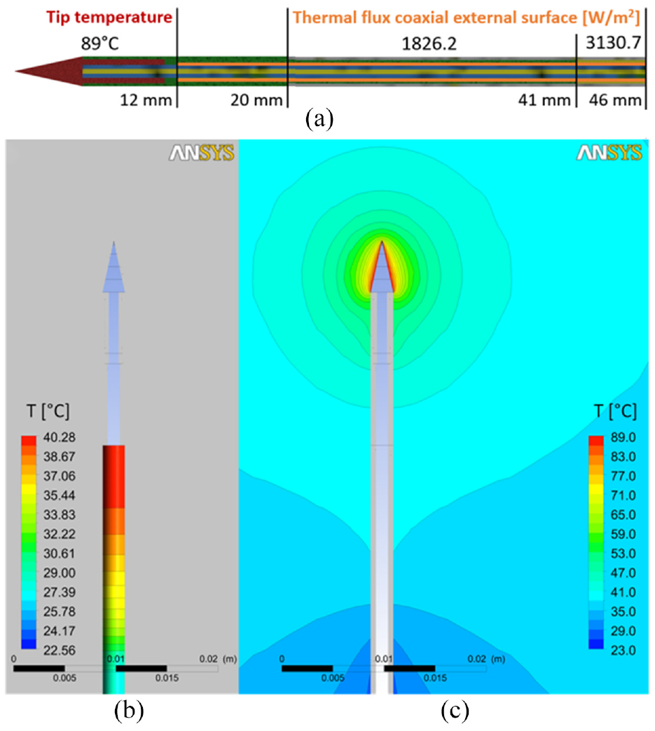
(a) Heating boundary conditions, (b) Temperature contour on the shaft, and (c) in the tissue with a coolant flowrate of 3.5 ml/min.
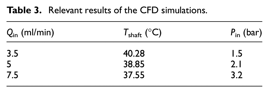
The relevant results obtained by the CFD simulations are reported in Table 3. The most appropriate cooling flowrate Qin was identified by pursuing a balance between the peak temperature recorded on the shaft Tshaft and the feeding pressure Pin. Considering the common performance of the commercially available peristaltic pumps, the value of 3.2 bar is unacceptable and 2.1 bar is not easily achievable. Accordingly, the flowrate of Qin = 3.5 ml/min and feeding pressure of 1.5 bar were chosen as set parameters for the cooling system.
Relevant results of the CFD simulations.
Mechanical design and prototyping
Based on the MWA probe architecture, including also the cooling system components, the mechanical design of the whole device was carried out considering two subsystems: the “insertion” and the “handling” ones.
The insertion subsystem is the MWA part actually penetrating the body and the organ of the patient, therefore its diameter has to be reduced to minimize the surgical wound (target #1 in Table 1). Due to miniaturization requirements, small-scale production issues are relevant, also considering budget constraints and project timing. Therefore, the technological analysis was aimed at implementing, where possible, off-the-shelf components, slightly modified or customized. For the feasibility of the other components, AM technologies were assessed. A summary of the identified solutions is reported in Table 4.
List of components of the insertion subsystem.
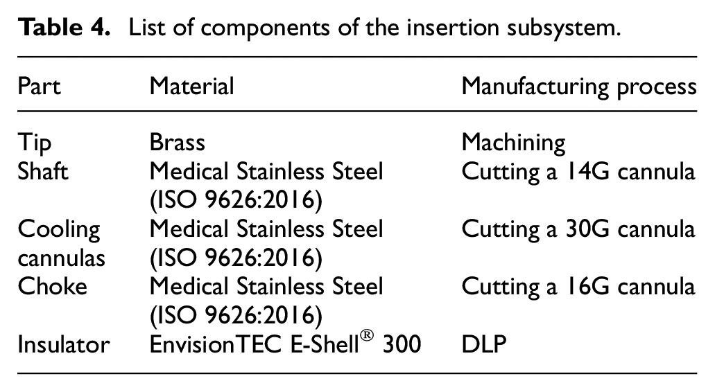
The brass tip was obtained by traditional machining, whereas the shaft, the cooling cannulas and the choke, made of stainless steel, were realized by cutting off-the-shelf cannulas with appropriate dimensions.
The prototyping of the insulating component, in its optimal geometry (Figure 8), represented a challenge, as the high aspect ratio of the component (target #1 in Table 1) requires a demanding manufacturing resolution. Due to thin and slander walls, conventional machining technologies are not adequate for fabricating such a component in Teflon (PTFE, typically used for this application), while molding technologies are not cost-efficient for prototyping. Accordingly, several AM techniques, suitable for the production of complex polymeric components with features at the micro scale, were evaluated, and the DLP technology was selected.
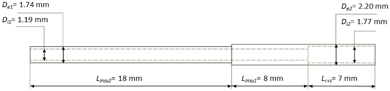
Measures of the insulating component.
The DLP technology is based on the working principle of projection stereolithography, thus the overall resolution and surface quality of the final parts are imposed by the resolution of the digital mask projecting the UV light pixel pattern onto the photocurable resin.33–35 However, the accuracy of a DLP system can be improved by using high-resolution Digital Mirror Devices (DMDs) 33 and appropriate anti-aliasing and gray-scaling strategies. The projection principle also implies that the overall manufacturing time depends on the selected layer height and the maximum height of the parts with respect to the building table, but not on the part size in the X and Y plane and the part number. Based on these considerations, DLP proves to be one of the most suitable processes for the rapid prototyping of such an insulating component, also considering the short life-cycle of MWA probes that might entail the manufacturing of several prototypes.
The base material was also investigated, according to the functional requirements of the specific component: the E-Shell® 300 by EnvisionTEC, specific for medical applications, was selected for its biocompatibility (Class IIa according to the ISO 10993), mechanical resistance (tensile strength 51.6 MPa) and resistance to high temperatures (nominal glass transition in the range 86°C–160°C, ASTM Method D570-98).
Besides complying with the optimal EM design, the executive design of the insulating component also considered the fabrication process. Indeed, the geometry was specifically adjusted to be manufactured using the DLP system, that is, the EnvisionTEC Micro Plus HD, characterized by high resolution (30 µm in the XY plane and 25 µm along Z-axis).
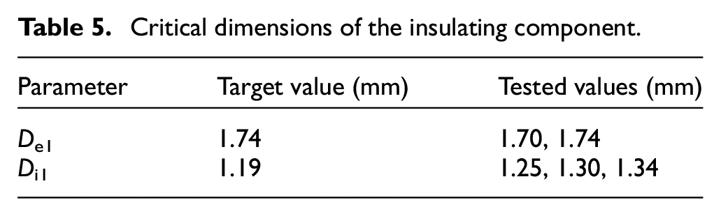
With reference to Figure 8, De1 and Di1 turned out to be the most critical dimensions, as they define a hollow cylinder characterized by the combination of extremely low thickness (about 0.2 mm) and considerable length (18 mm). Therefore, an experimental campaign was carried out to assess the process performance: in particular, the trials aimed at adjusting the geometrical values set by the EM design to compensate for process inaccuracies when manufacturing miniaturized components. In this experimental campaign, all the combinations between the De1 and Di1 values in Table 5 were tested. The components were manufactured by setting a proper orientation to facilitate the resin evacuation and prevent its accumulation at the interface where the inner channel diameter variates (Figure 9). Moreover, the components were positioned directly on the building table in order to avoid the use of supports, whose subsequent removal could affect the final part geometry and lead to part breakage. According to the results of the experimental campaign, De1 = 1.70 mm and Di1 = 1.30 mm proved to be the best dimensions capable of compensating the process inaccuracies properly; therefore, these values were set for the DLP manufacturing. With the choices described above, the manufacturing time for all the components (five for each dimension combination) is 1.40 h.
Critical dimensions of the insulating component.
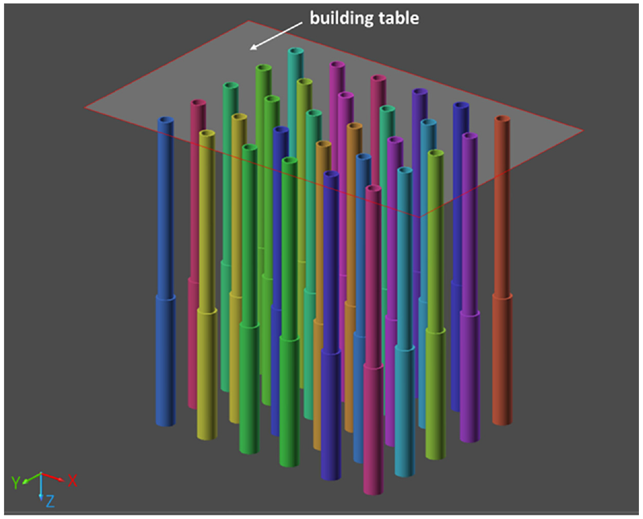
Component placement for DLP manufacturing.
It is also worth mentioning that the inner channel size requires an accurate cleaning phase to remove the remaining uncured resin; to this aim, the manufactured components were subjected to isopropyl alcohol washing within an ultrasonic bath and a further clearing of the channels was performed with the aid of a syringe.
In conclusion, despite the criticality exhibited by the high aspect ratio of the insulating component, a proper setting of DLP process parameters to compensate process inaccuracies, an appropriate part orientation on the building plate and a very accurate post-processing (including cleaning and post-curing) allowed to fabricate the component successfully.
The design of the handling subsystem (Figure 10) was aimed at a smart and affordable arrangement of cooling fluid inlet/outlet and MW power supply cables. This is not trivial, considering that the backward fluid flowing “freely” out of the shaft (see Figure 4) needs to be conveyed; at the same time, the four cannulas have to convey the fresh fluid from the upstream circuit and the coaxial cable need to be interfaced with the power source cable. The implemented solution relies on a three-ways “T” tube connector, interfacing as follows:
(1) one way hosts the probe, with a part of the shaft inserted and sealed by means of epoxy resin;
(2) one way let to drain the backward fluid by means of a tube;
(3) the coaxial cable and the cannulas come out from the shaft and pass through the opposite connector way; also in this case, epoxy resin sealing ensures water tightness.
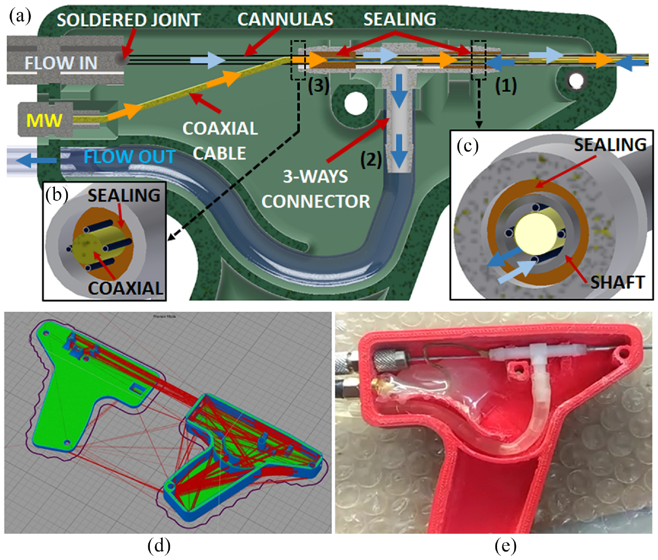
Handling subsystem design: (a) General arrangement of inputs and outputs, (b) detail of the assembly at interface (3),(c) detail of the assembly at interface (1), (d) FDM slicing of the two parts of the handling case (software: Simplify3D), and (e) detail of the interior of the prototype.
Upstream, the cooling system capillary tubes are welded with a stainless steel commercial fluid connector as interface with the water tube coming from the pump. The coaxial cable is instead connected to a standard RF plug; both the fluid and RF connectors are integrated into the handling cover wall.
The handling casing was obtained by two complementary parts assembled by screw connections: each part is made of PolyLactic Acid (PLA) and realized by FDM, due to the resolution required by the part, much lower than the one characterizing the insulating component. The handling casing was designed with planar lateral surfaces, thus avoiding, by a proper placement on the building table, the need for supports for the realization of the two sub-parts (Figure 10(d)). The machine used in this case was the GiMAX 3D S2. The two parts were realized in a single run, taking about 450 min, with printing speed set at 3000 mm/min and the temperature of the nozzle at 230°C.
Prototype testing
The 14G MWA assembled prototype was tested via ex vivo experiments performed on bovine liver (Figure 11). The probe was first connected to a Vector Network Analyzer (VNA) for the scattering parameter S11 measurement and considering impedance matching condition. The result showed a S11 average intensity of about −25 dB, with good impedance matching with a bandwidth of about 200 MHz. Then, the MWA probe was connected to the MW power generator to proceed with the ablation tests on the bovine liver. Different trials were performed to evaluate the axial ratio of the ablated area (target #4 in Table 1) by varying the input MW power and considering same treatment times (10 min). The results are reported in Table 6. During each ablation treatment, the used MW power generator was also capable of measuring the return loss: the recorded values showed that less than 3% of the provided input MW power was reflected back to the power generator, thus proving the good impedance matching of the antenna throughout all the experiments, despite the expected variation of the tissue dielectric properties induced by the heating treatment. A probe thermometer, inserted 20 mm apart from the MWA probe insertion point, was used to monitor the maximum temperature of the surrounding tissue: during all treatments the value did not exceed 41°C, demonstrating the proper functioning of the cooling system circuit. On the other hand, the flow rate suffered significantly from the relevant pressure drops, likely due to the unknown roughness of cannula inner surfaces, which affects the liquid flow, especially at the microscale. However, the tests successfully validated the manufacturing and assembly choices, and, in particular, demonstrated adequate stiffness and resistance to typical mechanical and thermal stress of components and joints and, finally, reliable sealing of all connections.
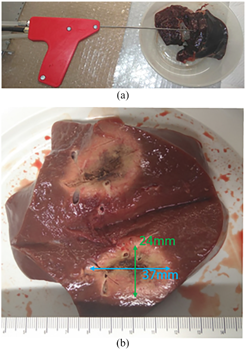
(a) Ex vivo experimental setup and (b) bovine liver tissue dissected after MW ablation.
Ex vivo experiments: Set up parameters and measured axial ratio.
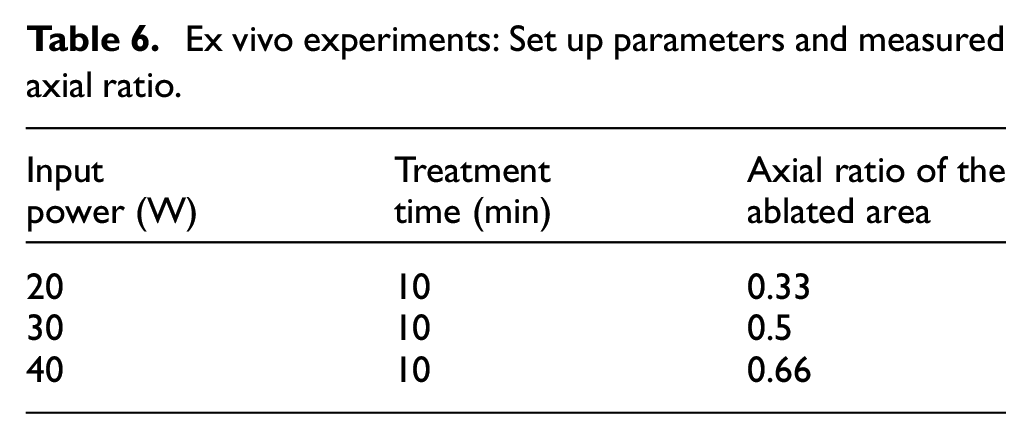
At the end of the ablations, the liver was dissected to evaluate the axial ratio of the ablated zone: as shown in Table 6, the best result was achieved by supplying 40 W for 10 min, obtaining an axial ratio of about 0.66, in good agreement with the 0.73 value obtained in the simulations reported in Portosi et al. 24
Discussion
The multidisciplinary perspective required by MWA probes – and by cancer ablation probes in general – makes the prototyping and testing phase crucial for the validation of the device final design. In particular, combining miniaturization with electromagnetic and thermal performance is extremely challenging, as manufacturing accuracies and tolerances may lead to deviations of the real operation behavior of the probe compared to the simulated one. Therefore, as reported in this paper, relating the main device targets with the manufacturing and prototyping challenges is crucial to optimize the device development, thus reducing the overall time-to-market. The 14G MWA choke-dipole probe presented in the paper exhibited performance in good agreement with the simulations. Moreover, they are also satisfying if compared with performance results related to 7 GHz choke dipole probe, reported in one of the most recent review available in literature 10 : in that case, with a supply power of 30 W, a treatment of 5 min led to obtain an ablation zone of 4.1 cm × 2.7 cm and an axial ratio of 0.66. Comparing these results with those reported in the previous section “Prototype testing”, it can be claimed that same axial ratio (0.66) obtained with the 14G MWA probe object of this paper can be conservatively assessed as a good result, especially considering lower operation frequency (2.45 GHz). Moreover, the 7 GHz MWA probe considered for comparison has an overall diameter of 3.5 mm, which is much higher than the one of the device proposed in this paper.
From the overall prototyping perspective, the use of AM technologies for the realization of surgical tools provide several advantages. The design flexibility is significantly higher, enabling complex designs and personalized treatments.27,28 Focusing in particular on tools for cancer surgery, there are several examples in literature of devices for ultrasound-based surgical treatments guided by Magnetic Resonance Imaging (MRI)36–39 and MR-guided biopsy. 40 In the device presented in this paper, AM techniques were used in the device prototyping phase, in particular to cope with the realization of a single component, thus avoiding to rely on Injection Molding, which is not cost-effective for small batches, besides requiring higher setting times and steps.
The insulating component is a crucial part of the presented MWA probe, as its properties directly affect the emitted radiation and its thermal insulation is crucial toward minimal invasiveness and overall tool efficiency. The selected AM technology, that is, DLP, allowed to successfully prototype the component, which is characterized by challenging features, such as section variation, thin walls (with a minimum thickness of 0.215 mm) and high aspect ratio (about 24.5 for the inner channel with diameter Di1 = 1.19 mm). On the other hand, realizing the handling part via FDM allowed to verify the design during prototype assembly, and slightly modify it aiming at the optimal arrangement of the hosted components, cables, and tubes.
Conclusion
In the field of medical devices, effective product development can be a critical issue, in which design, prototyping, and manufacturing phases are essential. Developing a cutting-edge cancer ablation probe means finding the optimal trade-off between geometry, ablation performance, and minimal invasiveness, in which manufacturing capabilities represent one of the most critical constraints. Realization and construction issues, together with material properties, increase the relevance of prototyping and testing phases for the progressive optimization of such devices. In this perspective, the present work aimed at showing how manufacturing challenges imposed by a 14G MWA probe prototype can be efficiently faced and coped with a flexible combined approach comprising optimized probe design and smart technological solutions.
In particular, alternative materials were proposed for the rapid prototyping of the complex geometry especially characterizing the insulating component of the MWA probe radiating part. To this aim, DLP was successfully exploited for its realization. Additionally, a proper mechanical design was proposed to facilitate the arrangement of all the components within the small volume of the MWA probe, including the cooling system, while preserving the minimal invasiveness requirement and easing the final device assembly, as well. The cooling fluid set parameters were identified based on CFD numerical simulation, pursuing a balance between the peak temperature on shaft surface and the feeding pressure, and considering the typical performance of the peristaltic pumps commonly implemented; as result, Qin = 3.5 ml/min and Pin = 1.5 bar were chosen as flowrate and pressure set parameters. The probe handling was thoroughly designed to optimize the arrangement of inner cables and ducts. Moreover, the external casing was fabricated by using PLA and the FDM technology, thus enabling fast and low-cost prototyping. Finally, the assembled 14G MWA probe prototype was tested via ex vivo experiments conducted on bovine liver. The experimental results highlighted that:
- from a structural point of view, the probe exhibited adequate stiffness to penetrate the tissue, and the whole assembly did not suffer any criticality during the ablation treatments;
- regarding the performance, the probe exhibited good impedance matching during all treatments, with a MW efficiency up to 97%; the best measured axial ratio of the ablated area was about 0.66, obtained by supplying a MW power of 40 W for 10 min.
Footnotes
Declaration of conflicting interests
The author(s) declared no potential conflicts of interest with respect to the research, authorship, and/or publication of this article.
Funding
The author(s) disclosed receipt of the following financial support for the research, authorship, and/or publication of this article: This research was developed within the “Sinach – Integrated systems for mini-invasive surgical navigation” project, supported by Puglia Region (Italy) through the Regional Operation Program POR FESRFSE 2014-2020, Innonetwork action, grant no. BLNGWP7.