
Abstract
Milling, as a common machining method, is widely used in rough machining and final finishing of various materials. In this paper, according to the milling temperature produced in the milling process, the formula of heat distribution coefficient for workpiece milling is established. By means of Deform-3D finite element software to carry out orthogonal cutting simulation of workpiece, the influence of different machining parameters on milling heat distribution coefficient is studied, the optimal machining parameters are determined, and the milling temperature experiment is carried out to verify the simulation temperature. The experimental results show that the simulation temperature is very close to the experimental workpiece temperature, and the error is very small, which verifies the accuracy of the method. At the same time, the influence of different initial temperature of workpiece on the milling force and stability is also studied. The results show that proper heating of the workpiece can effectively improve the milling stability of the thin-walled parts.
Introduction
In the milling process of thin-walled parts, most of the power consumed by the plastic deformation of the workpiece is converted into heat and produces high temperature. Excessively high temperature will affect tool wear degree and tool life and machining accuracy, such as rapid tool wear and thermal expansion of the workpiece. In order to determine the thermal damage caused by temperature of the workpiece and to determine the suitable cutting conditions, it is necessary to study the milling temperature. Because end milling is an intermittent process, the tool is subjected to periodic heating and cooling, and the temperature change in the tool is more complex than that in turning, therefore the study of milling temperature is of great significance.
The study of temperature modeling in machining processes can be broadly divided into two categories: analytical model and numerical model. Analytical model starts from the cutting mechanism and simplifies the heat source into simple geometry and boundary conditions. Jaeger 1 proposed a moving heat source model and a matrix heat source model for the first time. On this basis, Hahn 2 assumed that the solution geometry was infinite medium, and established an analytical model of shear surface temperature. Trigger and Chao 3 modified this model by introducing a semi-infinite medium and an adiabatic boundary into the machining and workpiece surface. Loewen and Shaw 4 also adopted Jaeger’s moving heat source method, but they assumed that the shear plane as the heat source moved with the shear velocity rather than the cutting velocity. Many scholars have studied the temperature distribution in intermittent cutting process. In intermittent cutting, the tool constantly impact on the workpiece. Liang et al.5–7 proposed an improved rotor rub-impact model to predict this effect. McFeron and Chao 8 studied the ordinary circumferential milling process and predicted the average cutter-chip interface temperature through the analytical method. For intermittent cutting tools, Stephenson and Ali 9 used adiabatic boundary conditions to simulate the tool as a semi-infinite square column. The time-dependent heat flux and Green function were used to solve the differential equation, and the average cutting temperature in the contact area was measured using the tool-workpiece thermocouple. Based on this method, Rulescu and Kapoor 10 changed the adiabatic boundary conditions into convective boundary conditions with finite rectangular geometry. The same conclusion is obtained under both conditions, that is, the cutting temperature in continuous cutting is higher than that in intermittent cutting. Komanduri and Hou 11 described the temperature field of the workpiece and chip under different heat source models caused by the heat source formed by the shear plane and friction region. Molinari and Moufki 12 proposed a thermal-mechanical model of turning operation. This model can predict the temperature distribution of the cutter face in the direction of chip flow and the interaction between the chip and the cutter. Richardson et al. 13 used the moving heat source method to predict the workpiece temperature during dry milling, and he found that the heat transferred to the workpiece decreased with the increase of cutting speed or feed speed, which led to the decrease of workpiece temperature. Zoltán 14 developed a mathematical model to predict the transient changes of cutting temperature during intermittent cutting by phenomenological methods, and the validity of the model was verified by temperature measurements in the literature. On the other hand, numerical models based on finite element method (FEM) and finite difference method (FDM) can solve more complex cases at the cost of computation time. Tay et al. 15 were the first to use the finite element method to calculate the temperature distribution of orthogonal cutting. They used the finite element method to solve the two-dimensional steady-state energy equation and numerically solved the temperature distribution under typical conditions of continuous orthogonal chip machining. Strenkowski and Moon 16 proposed an Euler finite element model to simulate orthogonal metal cutting, which can predict chip geometry and the temperature distribution in the workpiece and tool without empirical cutting data. In order to simulate the orthogonal cutting process, Lin et al. 17 established a coupled model including FDM and FEM. In this model, FDM was used to predict the temperature in the tool-chip interface during continuous cutting, and the intermittent cutting process was simulated by numerical method. Kim et al. 18 proposed a finite element method for predicting temperature and stress distribution in micromachining process. Deform2D software was used by Ozel and Altan 19 to simulate end milling operations and to predict the stress on the tool and the cutting temperature. Lazoglu and Altintas 20 used FDM to model cutting temperatures in continuous and intermittent cutting. In order to avoid rapid tools wear, cutting parameters should be selected to reach the lower temperature of the diffusion limit of the tool material. Ulutan et al. 21 proposed a model based on the finite difference method (FDM) to determine the three-dimensional temperature field on the chip, cutter and workpiece in the cutting process. Yang et al. 22 used the three-dimensional finite element method coupled with thermal-mechanical effect to model the micro-end milling process, and studied the temperature distribution of the micro-tool in the micro-end milling process by combining numerical simulation and experiment. In order to determine the thermal displacement of the workpiece during dry milling, Sölter and Gulpak 23 developed a finite element method using the inverse process to determine the heat distribution. Chen et al. 24 established a plastic failure material model based on energy density by using the finite element method to simulate the micro-cutting process and identify the temperature of workpiece surface and tool tip in the predicted micro-cutting temperature field. Lazoglu and Bugdayci 25 used a semi-analytical method to model the cutting forces during milling and calculated the heat generated through the thermal zoning method. Islam et al. 26 proposed a three-dimensional model using FDM to predict the temperature distribution during continuous cutting. In order to better determine the state of the workpiece surface, Miao et al. 27 analyzed the influence of machining parameters on specific materials in machining. Zhang et al. 28 established a complete dynamic model of thin-walled workpiece milling system. Duan et al. 29 summarized the research progress of cutting force model and determined the problem of cutting force modeling. Kuang et al. 30 systematically expounded the influence of common mechanical processes on the wear performance of machined surfaces in terms of hardness, surface morphology, and residual stress.
In this paper, according to the milling temperature generated in the milling process, the generation, and transfer of heat in the cutting process are analyzed, and the formula of heat distribution coefficient in workpiece milling is established. This formula can be used to predict the temperature of each part in the milling process, and determine the optimal machining parameters on this basis, which lays a foundation for further improving the milling accuracy of thin-walled parts.
Milling temperature modeling
Figure 1 is a cross-section diagram of orthogonal cutting. As shown in the figure, there are three deformation zones during cutting. The first deformation zone is the area where the material is shearing, the second deformation zone is the contact area between the chip and the rake face of the cutting tool, and the third deformation zone is the contact area between the finished surface and the rake face of the cutting tool. All three deformation zones generate heat during the milling process. Assume that the total heat generated in the milling process in unit time is Q, and the heat generated in the first deformation zone is Qs, in the second deformation zone is Qf and in the third deformation zone is Qe respectively, so

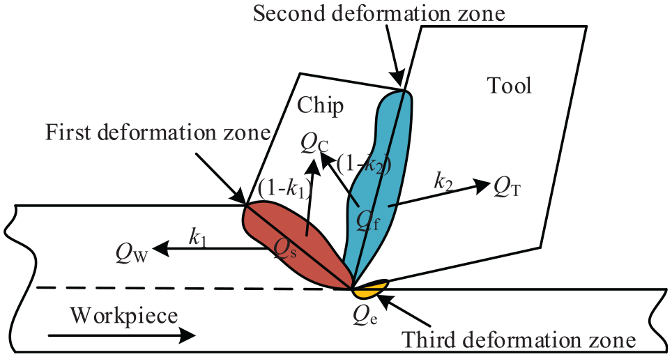
Heat distribution in milling deformation zone.
According to the conservation of energy, the total heat generated per unit time in the cutting process is equal to the cutting power consumed by the spindle motor, so there is

Where V is the cutting speed.
When the tool edge is very small, the heat generated in the third zone is very small and negligible. Therefore, the heat generated in the milling process mainly comes from the first deformation zone and the second deformation zone. The heat generated in the first deformation zone mainly flows into the workpiece and the chip, and the proportion of the heat flowing into the workpiece is k1 then the proportion of chip inflow is (1 − k1). Similarly, the proportion of the heat generated by the second deformation zone flowing into the tool is k2, then the proportion of chip inflow is (1 − k2). So there is


Where Qc is the heat flowing into the chip, Qw is the heat flowing into the workpiece, Qt is the heat flowing into the tool.
Because this paper only studies the temperature of the workpiece, only the heat generated in the first deformation zone is analyzed. The heat generated in the shear plane per unit time is

Where Fs is the shear force of the shear plane, Vs is the shear velocity, and its expression is
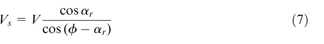
Where αr is the tool rake angle and ϕ is the contact angle. According to the principle of maximum shear stress, the contact angle can be expressed as
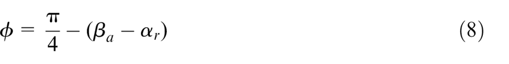
Where βa is the friction angle, which is the sine function of the friction factor.
The shear force can be expressed as a function of the milling forces in the x and y directions

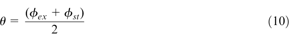
Where, Fx and Fy is the average milling force of one period, and the heat source intensity corresponding to the average of the entry and exit angle is taken as the average heat source intensity, so the average contact angle is
The power in the first deformation zone will be converted into heat flowing into the workpiece, thus causing the temperature of the workpiece to rise. The expression is

Where Tr is ambient temperature, Tw is workpiece temperature, and Tt is tool temperature. mc is the metal removal rate, and cs is the specific thermal coefficient of the workpiece material.
The metal removal rate can be determined by cutting conditions

Where ρ is the workpiece material density, and ae is the radial cutting width.
Milling heat distribution coefficientof thin-walled parts
Thin-walled parts are easy to be thermal deformed due to high temperature, so it is very important to study the temperature of the workpiece in milling process. Through milling heat distribution coefficient k1, we can know the heat flowing into the workpiece, so as to predict the workpiece temperature. However, the value of milling heat distribution coefficient is different under different cutting conditions, so it is very important to obtain the workpiece milling heat distribution coefficient under different conditions. In this paper, an exponential expression is proposed to express the relationship between milling heat distribution coefficient and cutting parameters such as spindle speed, radial cut depth, axial cut depth, and feed per tooth. The expression is
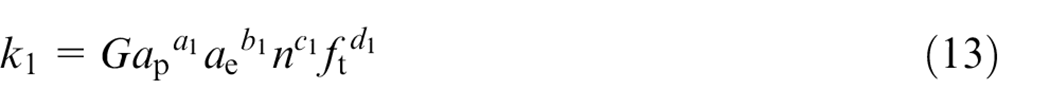
Where n is the spindle speed, ap is the axial cutting depth, ft is the feed rate per tooth, and G is the constant term.
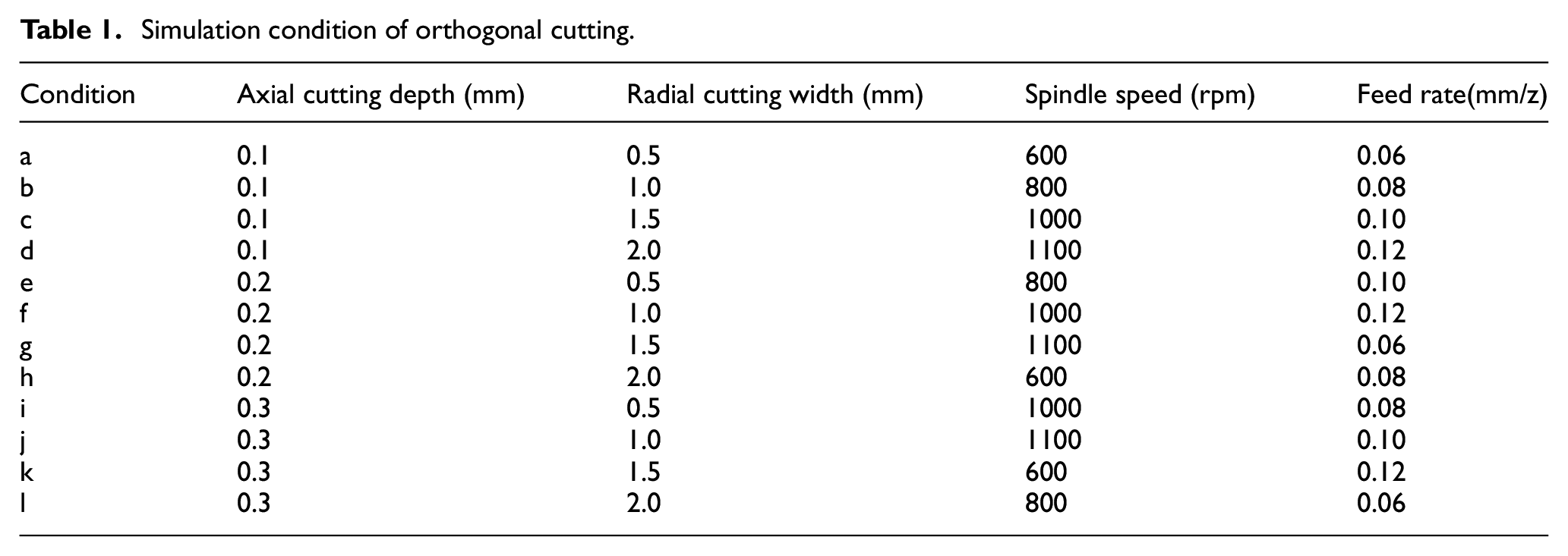
In order to obtain each index in equation (13) and determine the influence of each cutting parameter on the milling heat distribution coefficient, orthogonal milling conditions with four factors and four levels as shown in Table 1 were selected, and Deform-3D software was used to simulate milling, so as to obtain the change of milling temperature with time under different parameters.
Simulation condition of orthogonal cutting.
The simulation results obtained are shown in Figure 2, which simulates the process of a cutter tooth from cutting in to cutting out. It can be seen from Figure 2 that the highest temperature is in the contact area between the cutter and the workpiece, which is consistent with the milling temperature model established in Figure 1. Moreover, it can be seen from the figure that under the conditions defined in this paper, the heat flowing into the chip is the most, so the chip is the brightest color except for the cutting point in the 12 conditions in the figure. It can also be seen from the figure that the maximum temperature in the cutting area is different with different cutting conditions.
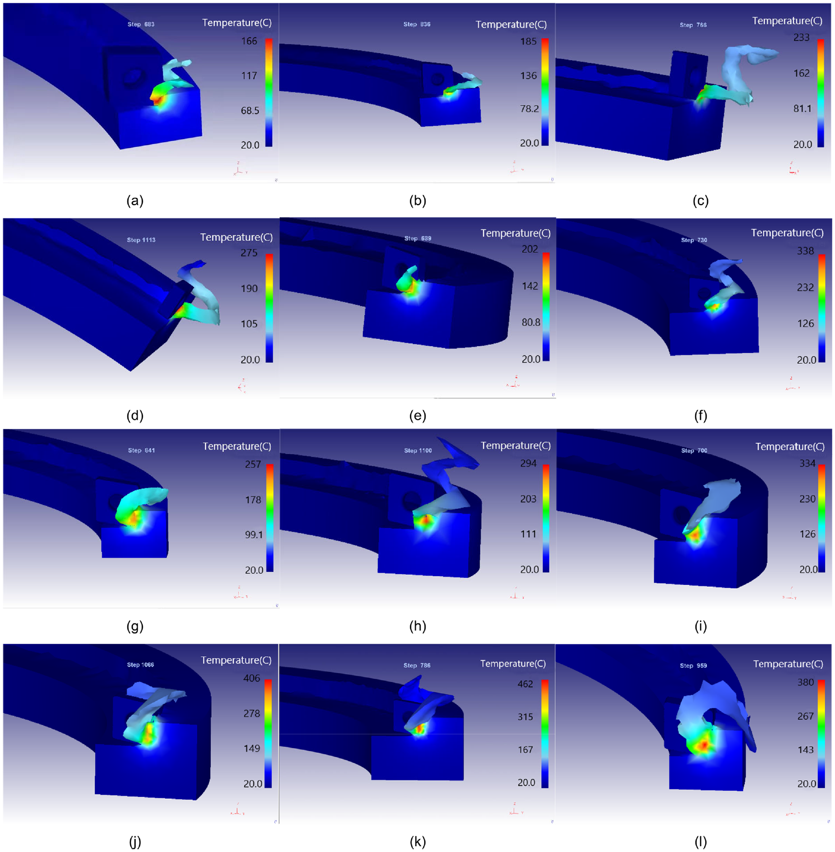
3D simulation results of each milling in Table 1.
The curves of workpiece temperature variation with time obtained through simulation are shown in Figure 3. It can be seen from the figures that the temperatures under all cutting conditions increase gradually and then remain constant. The main reason is that when the cutter tooth start cutting, the temperature gradually increases with the increase of cutting thickness. When the cutter tooth start stable cutting, the temperature also reaches a stable state. This indicates that the influence of cutting parameters, radial cutting depth, spindle speed, and feed rate of each tooth on the temperature is different.
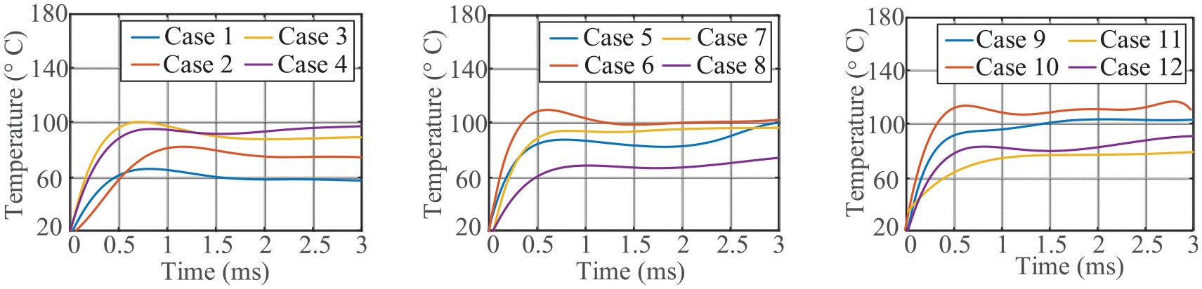
Workpiece temperature simulated by DEFORM-3D.
The steady-state temperature of the workpiece under various conditions in Figure 3 was taken as the average temperature of the workpiece, and the corresponding milling heat distribution coefficients of the workpiece were obtained through the milling stability model, as shown in Table 2.
Average temperature and heat distribution coefficient of workpiece.
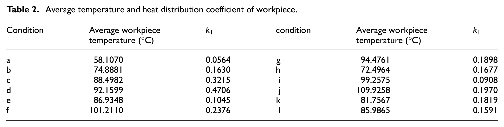
In order to make the change of heat distribution coefficient of workpiece more intuitive, 12 values of k1 are marked in Figure 4.
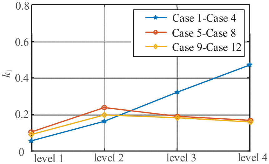
Heat distribution coefficient of workpiece.
It can be seen from Figure 4 that the heat distribution coefficient obtained by the four cutting cases with axial cutting depth of 0.1 mm gradually increases. Even in the fourth case, the heat distribution coefficient of the workpiece is close to 50%, which means that half of the heat generated in the milling process flows into the workpiece and easily causes thermal deformation of the workpiece. The overall heat distribution coefficient of the four cutting cases with axial cutting depth of 0.2 mm are slightly higher than that of the four cutting cases with an axial cutting depth of 0.3 mm, which indicates that the influence of axial cutting depth on the heat distribution coefficient of workpiece is less than that of other cutting parameters.
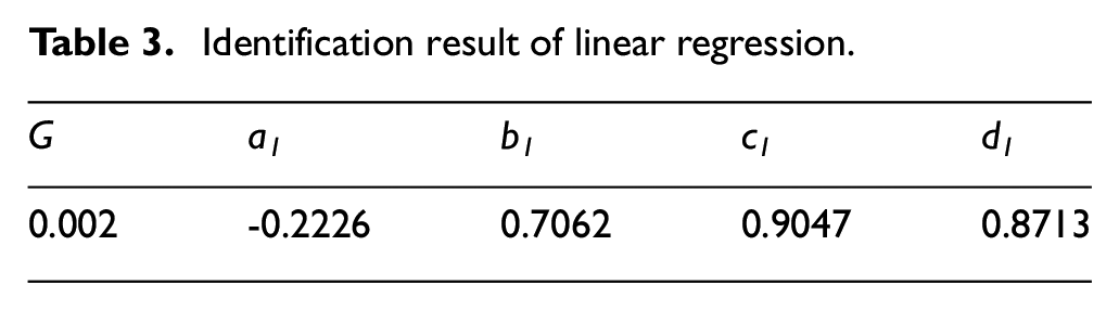
The indexes of equation (13) can be obtained by using the regression algorithm, as shown in Table 3.
Identification result of linear regression.
Influence of initial temperature of thin-walled parts on milling stability
When the initial temperature of the workpiece is higher than room temperature, in addition to the heat generated in the milling process, there is also heat due to the high temperature of the workpiece. The two kinds of heat affect each other, so the milling stability of the thin-walled parts at this condition is different from that at room temperature. In order to study the milling stability of thin-walled parts at different temperatures, Deform-3D was used to simulate the heating milling of the workpiece in case 1 and case 5 in Table 1. The temperature of the workpiece was heated to 20°C, 250°C, and 500°C, respectively. The specific milling conditions are shown in Table 4.
Milling parameters.
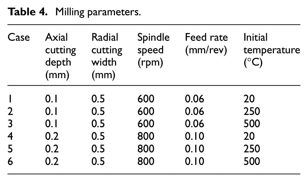
The obtained simulation results are shown in Figures 5 and 6. Figure 5 shows the milling results of three cases of different initial temperatures of the workpiece with axial cutting depth of 0.1 mm, and Figure 6 shows the milling results of three cases of different initial temperatures of the workpiece with axial cutting depth of 0.2 mm.
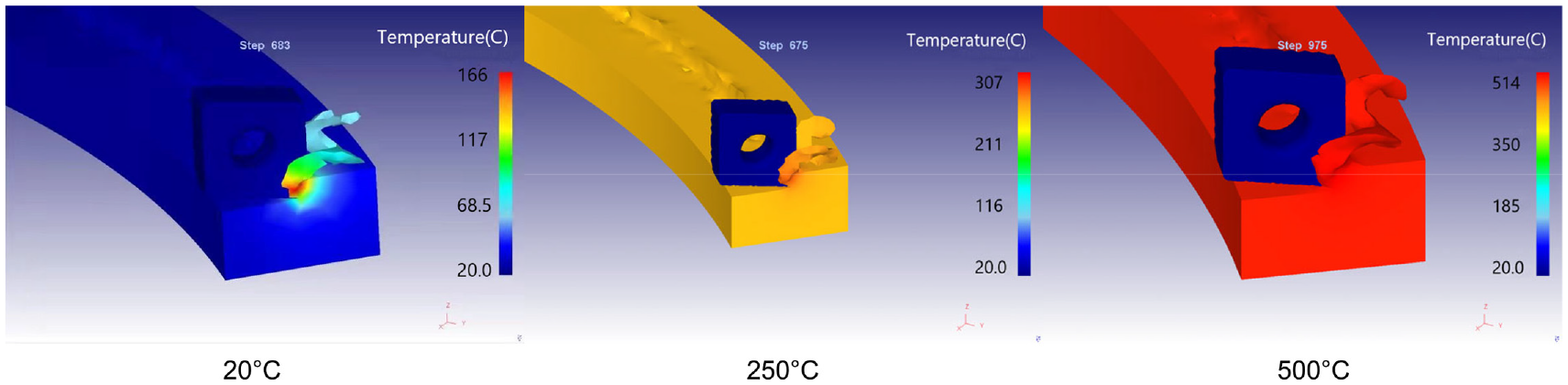
Simulation of workpiece milling at different initial temperatures when ap = 0.1 mm.
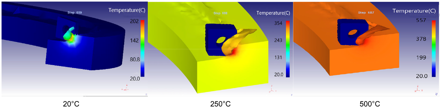
Simulation of workpiece milling at different initial temperatures when ap = 0.2 mm.
It can be seen from Figures 5 and 6 that the higher the initial temperature of the workpiece, the highest temperature of cutting zone is more close to the workpiece initial temperature. That is to say, the workpiece heating caused by the heat generated during the cutting of thin-walled parts is far less than that caused by the heating of the workpiece, so only heat produced by thermal affect the stability of the thin-walled workpiece. Therefore, only the influence of heat generated by heating the workpiece on the stability of thin-walled parts can be considered.
Figure 7 shows the milling forces in x, y, and z directions generated by the workpiece cutting at three different initial temperatures with axial cutting depth of 0.1 mm. Similarly, Figure 8 shows the milling forces in x, y, and z directions generated by the workpiece cutting at three different initial temperatures with axial cutting depth of 0.2 mm. It can be seen from Figure 7 and Figure 8 that with the increase of the initial temperature of the workpiece, the milling force decreases in all three directions, especially in the x direction. At the same time, the amplitude of milling force variation in one cycle also decreases, which indicates that the cutting force is more stable and the cutting is also more stable. The main reason is that the high temperature will change the material properties of the workpiece, resulting in the reduction of the workpiece stiffness, and the increase in cutting temperature will lead to the toughness and strength of the tool are also increased, so the milling force will be reduced when cutting the workpiece.
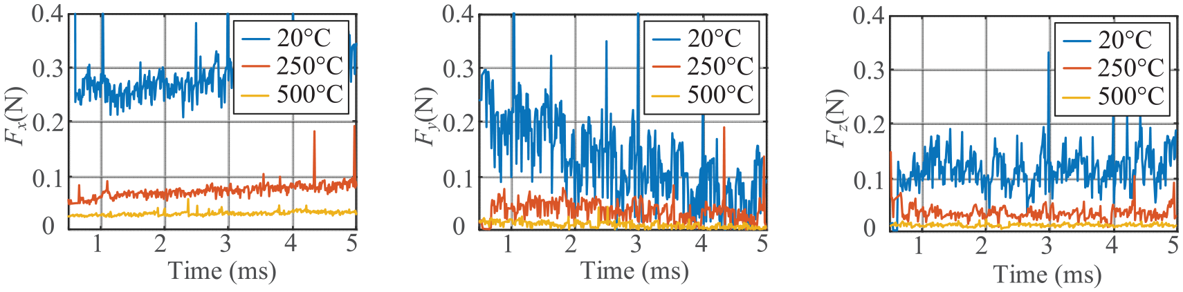
Simulation force of workpiece milling at different initial temperatures when ap = 0.1 mm.
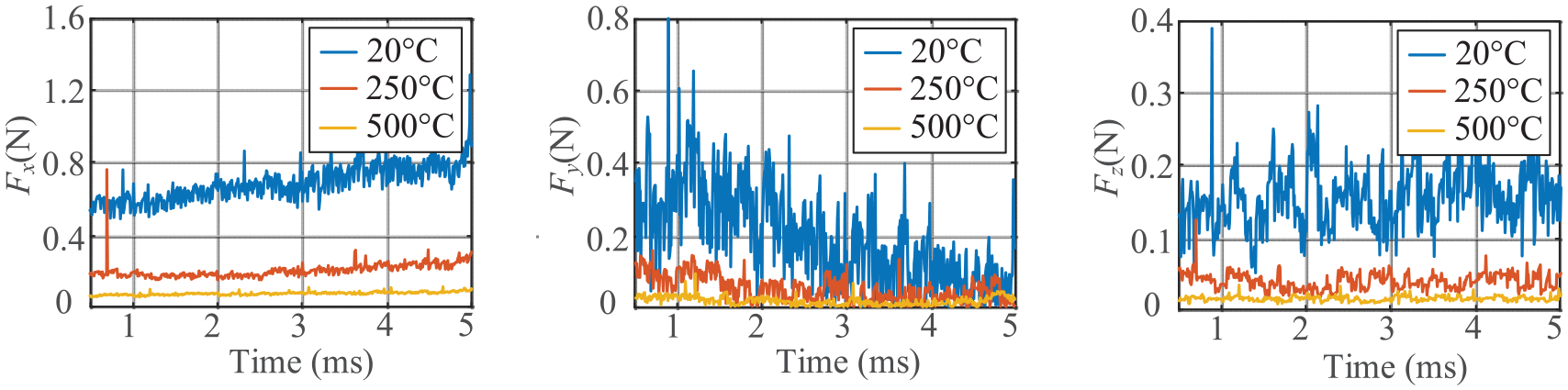
Simulation force of workpiece milling at different initial temperatures when ap = 0.2 mm.
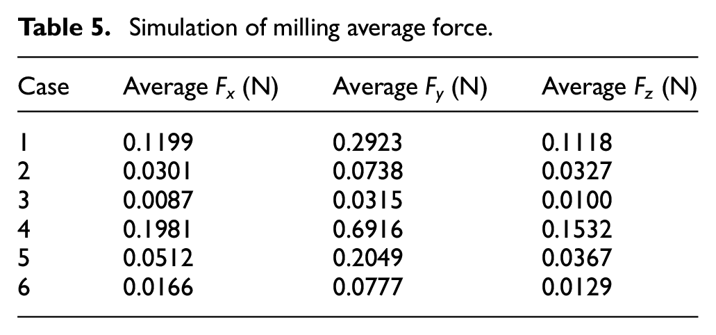
The milling forces in each direction obtained in Figures 7 and 8 are shown in Table 5. It can be clearly seen from Table 5 that when the initial temperature of the workpiece increases from 20°C to 250°C, the milling force decreases greatly. When the temperature increases from 250°C to 500°C, the milling force has been very small, so the reduction of milling force is relatively small, and the change of milling force is not obvious when the workpiece temperature is heated to a higher level.
Simulation of milling average force.
Since the simulation can only obtain average force, the average force method is adopted to identify the milling force coefficients under three temperature conditions. The results are shown in Table 6.
Milling temperature.
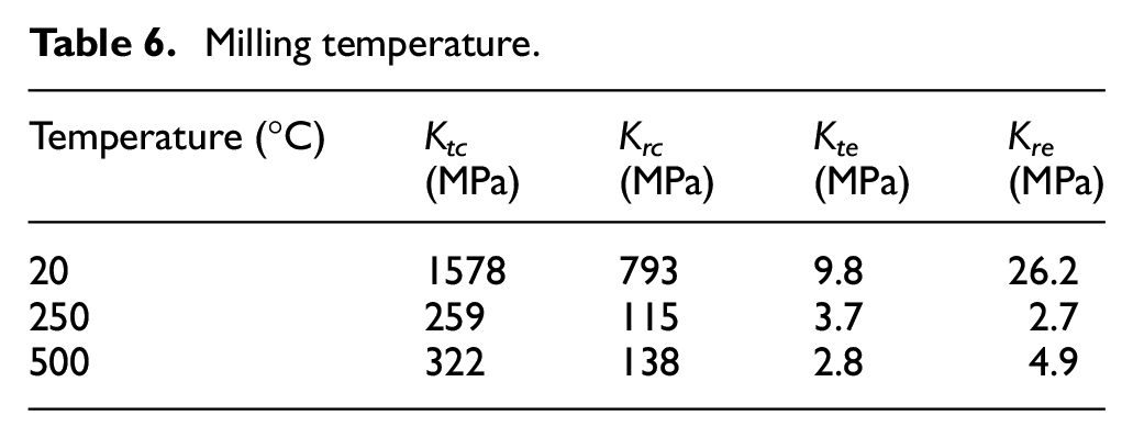
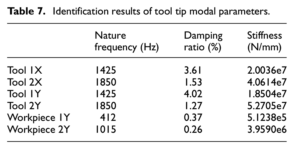
It can be seen from Table 6 that with the increase of the initial temperature of the workpiece, the milling force coefficient also gradually decreases, which indicates that the increase of the initial temperature of the workpiece can make the cutting easier. When the three groups of milling force coefficients in Table 6 are used for stability prediction, the stable blade diagram obtained is shown in Figure 9. The modal parameters of tool and workpiece are shown in Table 7.
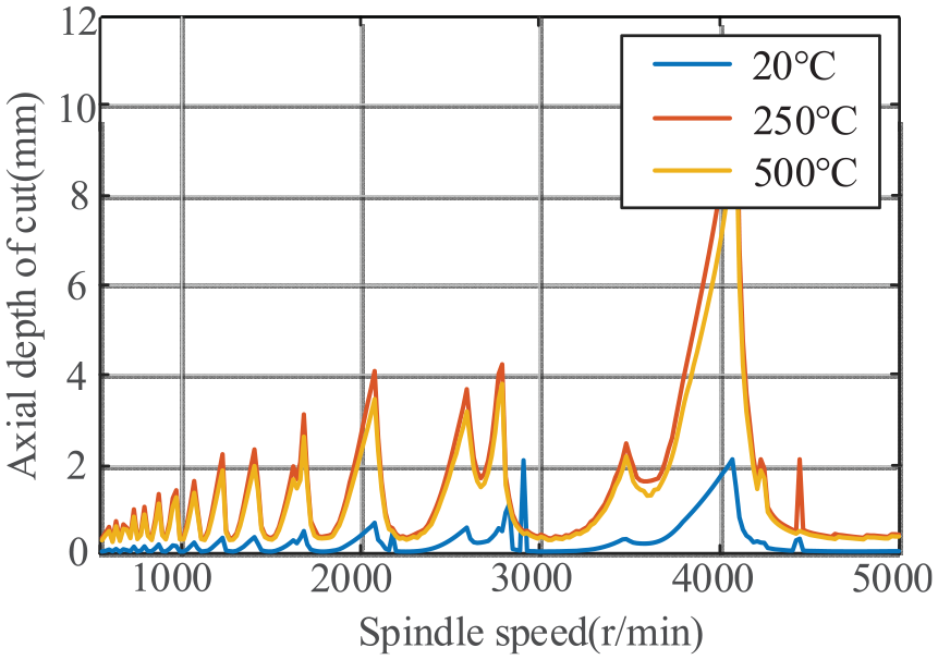
Stability lobe diagram of different temperature.
Identification results of tool tip modal parameters.
It can be seen from Figure 9 that the stability of the workpiece at the initial temperature of 250°C and 500°C is significantly higher than that at the initial temperature of 20°C, indicating that heating the workpiece can effectively improve the milling stability. It can also be seen from Figure 9 that the axial critical cutting depth corresponding to each rotational speed at the workpiece initial temperature of 250°C is slightly greater than that at the workpiece initial temperature of 500°C, indicating that the stability of the workpiece at the initial temperature of 250°C is greater than that at the initial temperature of 500°C, which is consistent with the change of milling force in Table 6. This shows that the initial temperature of the workpiece is not as high as possible. However, heating the workpiece in an appropriate temperature range can improve cutting stability. If the temperature is too high, the milling stability will decrease.
Experimental verification of milling temperature
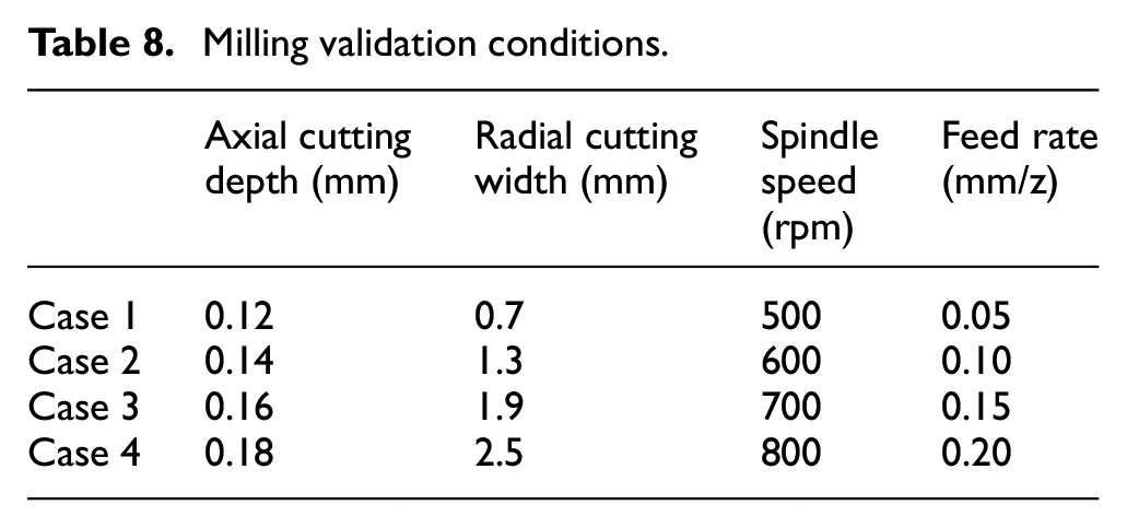
In order to verify the accuracy of the workpiece heat distribution coefficient k1, the workpiece milling temperatures under the four conditions as shown in Table 8 were predicted and verified by temperature measurements in milling experiments. In actual processing, an infrared imager of Fluke Ti32 is used to record the temperature of the workpiece in the milling process, as shown in Figure 10.
Milling validation conditions.
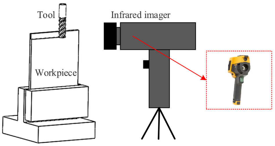
Temperature measuring equipment Fluke Ti32.
The temperature of each stage obtained by imager is shown in Figure 11. Since the temperature unit obtained by Fluke thermal imager is Fahrenheit, the temperature needs to be converted to Celsius. The transformation relationship between Fahrenheit and Celsius is: °C = (°F − 32)/1.8. Therefore, milling temperatures at four cutting cases are obtained as shown in Table 9
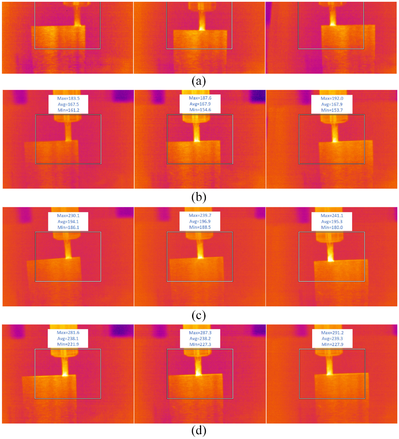
Milling temperature imaging results: (a) case 1, (b) case 2, (c) case 3, and (d) case 4.
Milling temperature.
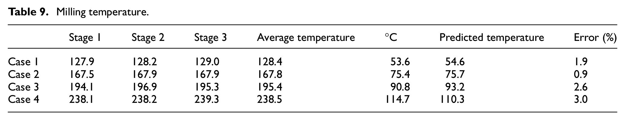
It can be seen from Table 9 that the temperature predicted by heat distribution coefficient k1 of the workpiece is very close to the temperature of the workpiece in actual processing, so the accuracy of heat distribution coefficient of the workpiece can be proved. Therefore, before the milling experiment, the machining parameters can be determined to predict the temperature of the workpiece in the milling process, which can greatly avoid the adverse effects of excessive temperature on the workpiece in the processing.
Conclusion
Milling heat has a very important influence on the milling stability in the milling process, so it is very necessary to study the milling temperature. This paper mainly studies two kinds of milling heat, and the specific work and research conclusions are shown as follows:
(1) The heat distribution coefficient of the workpiece will change at different cutting conditions. It is found through milling simulation that the larger the axial cutting depth is, the smaller the milling heat distribution coefficient is. At the same time, the milling heat distribution coefficient increases with the increase of spindle speed and feed per tooth.
(2) When the initial temperature of the workpiece increases, the milling forces in x, y, and z directions decrease. Mainly due to the increase in temperature, the rigidity of the workpiece is reduced, and the toughness of the tool is increased, so stable cutting can be carried out with a relatively small cutting force. From 20°C to 250°C, the milling force decreases significantly, the temperature continues to increase, and the degree of milling force decrease is very small.
(3) According to the stability lobe diagram of the three temperatures, it can be found that the stability region is the largest when the workpiece temperature is 250°C. When the temperature rises to 500°C, the temperature range decreases slightly, indicating that the higher initial temperature of the workpiece is not the better. Therefore, the optimal cutting temperature of the workpiece can be determined.
Footnotes
Declaration of conflicting interests
The author(s) declared no potential conflicts of interest with respect to the research, authorship, and/or publication of this article.
Funding
The author(s) disclosed receipt of the following financial support for the research, authorship, and/or publication of this article: This work is financially supported by the General Program of National Natural Science Foundation of China (Grant Nos. 51875093, 51105065), the Fundamental Research Funds for the Central Universities from Ministry of Education of China (Grant Nos. N180304017, N2103020), and the National Science Foundation for Postdoctoral Scientists of China (Grant Nos. 2014M551105, 2015T80269).