
Abstract
Chatter vibration is apt to occur when machining thin-walled parts with insufficient rigidity. The harmful excitation of periodical cutting forces can be mitigated by enhancing the dynamic stiffness or increasing the damping of the part. A composite viscous damper including air damping and eddy current damping is designed, which can be attached on the thin-walled part by the vacuum. Based on the formulations of air damping and eddy current damping, the optimal equivalent viscous damping is derived for achieving the maximum critical depth of cut. Furthermore, the geometries of the damper are determined for damping a specific thin-walled part after investigating its relationship with viscous damping. The modal test indicates that the damper can suppress multiple modes of the cylindrical thin-walled part, and the amplitude of the first mode of the frequency response function (FRF) is reduced by 57%. The composite viscous damper is applied to suppress the chatter and resonant vibration of the thin-walled part during machining. Milling tests demonstrate that the machining vibration is reduced by 55% and 76% after employing single damper and four dampers, respectively.
Introduction
Chatter vibration is apt to occur during the machining process of thin-walled parts due to its inadequate rigidity. Therefore, high-efficiency machining of thin-walled part with desired surface finish has become a challenge. An effective solution of machining process optimization has been reported in the literatures. 1 Sun and Jiang 2 presented an accurate modeling of dynamic milling system with the force-induced deformation effect. Sims and Turner 3 developed a time domain model of process damping, and explored the relationship between cutting conditions and the amplitude of chatter vibrations. Yang et al. 4 proposed a numerical solution based on perturbation and iteration methods to solve the cutting force, vibration, and chatter stability of thin-walled part milling. Liu et al. 5 proposed a tool inclination method based on the adoption of the cutting force component in the lowest stiffness direction of the thin-walled part to guarantee the machined surface finish. Zhang et al. 6 developed a complete dynamic model of thin-walled part milling system including multiple structural modes, and achieved the stability lobs by numerical integration. However, available selection of cutting parameters could be restricted due to low stability limit of thin-walled part, and the active or passive vibration control could be indeed powerful in this case.
Due to the easy implementation and effective vibration reduction, 7 passive vibration control has been widely used and can be realized via the vibration absorber (VA). The vibration energy of the primary structure is transferred by tuning the design parameters (i.e. stiffness and damping) of the VA based on specific optimization criteria. Sims 8 proposed an analytical method to improve the machining stability of low stiffness workpiece with single-DOF by increasing the negative real part of the FRF. Moradi 9 proposed the optimization of the VA position and spring stiffness under different milling conditions for the purpose of minimizing tool vibration. Nakano et al. 10 mounted a VA on a spindle by a rotating collet chuck to suppress chatter, and studied the optimum parameters of the VA for reaching the maximum critical depth of cut at different spindle speeds. Kolluru et al. 11 designed tuned viscoelastic dampers to minimize the vibration of thin-walled casings. Yang et al. 12 applied the VA to the turning tool, and proposed a parameter optimization method considering the background modes. However, the application of single-DOF VA is restricted with its narrow vibration suppression bandwidth. Afterward, multiple single-DOF VAs and multi-DOF VA are proposed to suppress multiple vibration modes, but their structural design and geometry optimization are much more complicated.
The VA is converted into the Lanchester damper when the stiffness is neglected, and is able to mitigate vibration via dissipating the vibration energy. The damping of the Lanchester damper can be realized by friction, impact, or viscoelastic materials. The friction damping dissipates the vibration energy by converting the kinetic energy into heat. Edhi and Hoshi 13 designed a friction damper to eliminate high-frequency chatter in boring processing. Impact damping dissipates vibration energy through the collision of impact particles. Ema and Marui 14 designed an impact damper for boring tools and suppressed the vibration in the direction of the principal cutting force. Yang and Wang 15 studied the mechanism of impact damping and investigated velocity responses of the damped cantilever beam. Paul et al. 16 mounted an impact damper on the bottom of the turning tool holder and reduced the tool vibration by 62%. Viscoelastic damping can be realized by utilizing the viscoelastic material and is able to dissipate vibration energy effectively. Kolluru et al. 17 mounted multiple viscoelastic dampers on a thin-walled cylindrical part and reduced the milling vibration by about 4.2 times. However, above principles of damping demonstrate strong nonlinear hysteresis characteristics when the relative velocity changes dramatically and frequently, especially for the case of machining process of flexible workpiece. The nonlinear hysteresis characteristics lead to unpredictable changes on the damping coefficient, and design guidelines for industrial applications are lacked so far.
Contrarily, damping behaviors of the viscous damping and eddy current damping can be well predicted, and a large amount of works have been reported. When the mass moves in the viscous fluid or magnetic field, it will be subjected to the viscous damping force or eddy current force proportional to the relative speed. Bae et al.18,19 formulated the eddy current damping and combined it with the VA. Yang et al. 20 developed an eddy current damper for milling thin-walled parts, and reduced the vibration amplitude by 85%. Gubanov 21 designed a viscous damper using air medium and applied it to suppress the chatter vibration of thin-walled part milling. Yan et al. 22 designed a lever-shaped eddy current damper and derived the relationship between leverage ratio and damping efficiency. Maksound and Mokbel 23 applied viscous damping on grinding by introducing high viscosity coolant for grinding chatter suppression. The viscous damping and eddy current damping are able to reduce the vibration within a large bandwidth, but their applications are limited due to low damping efficiency and large volume.
For the purpose of improving damping efficiency, a composite viscous damper including air damping and eddy current damping is proposed to maximize critical depth of cut for milling thin-walled parts. The remainder of the paper is organized as follows. In Section 2, the design of the damper is proposed. The air damping and eddy current damping are formulated respectively in Section 3. In Section 4, the geometries of the damper are optimized to improve machining stability for a cylindrical thin-walled part, and the numerical simulation is performed to predict the performance of the designed damper. Modal tests and milling tests are carried out to verify the vibration suppression of the composite viscous damper in Section 5. Finally, the paper is concluded in Section 6.
Structural design of the damper
The composite viscous damper is attached to the thin-walled part by a vacuum suction cup (Figure 1). A mass consisted of wolfram and copper part, as well as a cylindrical magnet, are included inside the damper. The mass is movable relative to other parts of the damper. The air is filled between the mass and the shell, which functions as the viscous medium.
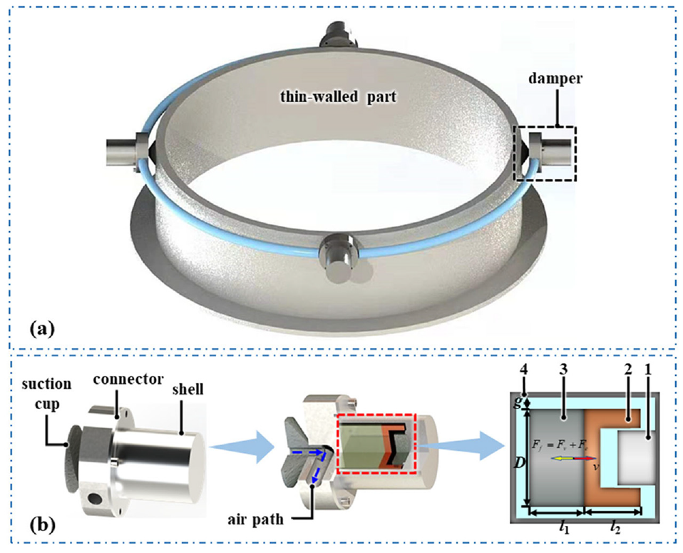
Design of the composite viscous damper: (a) external view and (b) internal view. 1-cylindrical magnet, 2-copper,3-wolfram, 4-shell.
When machining the thin-walled part, the shell vibrates together, generating a relative speed v with the mass. The air flows in the narrow gap between them due to the relative motion, resulting in the generation of air damping force Fa. Meanwhile, the eddy current force Fe is induced as the copper inside the mass moves in the magnetic field generated by the cylindrical magnet, which also contributes to a resistant force to the relative motion. The dual damping force, which is composited with the air damping force Fa and the eddy current damping force Fe, will thus prevent the mass from moving. The reaction of the damping force is finally applied to the thin-walled part, which aids in the reduction of machining vibration.
Formulation of the equivalent damping
Air damping
The flow rate Q of the air through the gap of concentric ring between the mass and the shell can be formulated by the equation (1). 24
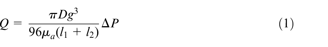
where g is the radial gap between the mass and the shell, D is the diameter of the mass, μa is the dynamic viscosity of the air, l1 is the wolfram length, l2 is the copper length, and ΔP is the pressure difference between the two flat end faces of the cylindrical mass.
Meanwhile, the flow rate Q is written as equation (2).
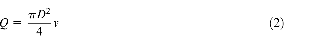
where v is the relative velocity between the mass and the shell.
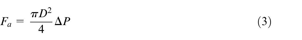
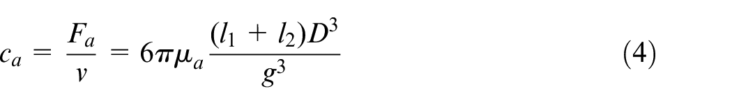
The air damping force Fa is generated by the pressure on the two flat end faces of the cylindrical mass, which is derived as equation (3).
Combining equations (1)–(3), the air damping coefficient ca of the damper can be obtained as equation (4).
Eddy current damping
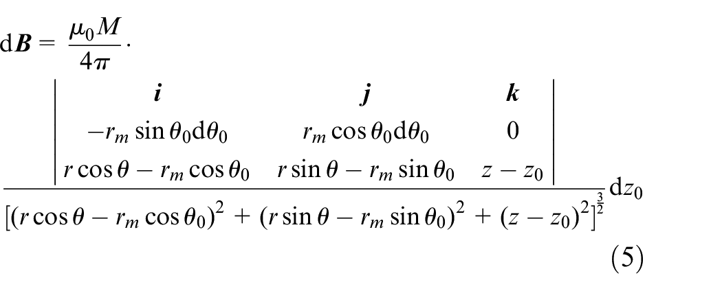
The eddy current damping force Fe is generated due to the motion of a conductor in the magnetic field (Figure 2). According to the Ampere’s Circuital Law, the magnetic field is generated by the molecular current of the magnetic. For the molecular current Q (rmcosθ0, rmsinθ0, z0) on the surface of the magnet, the magnetic induction intensity d
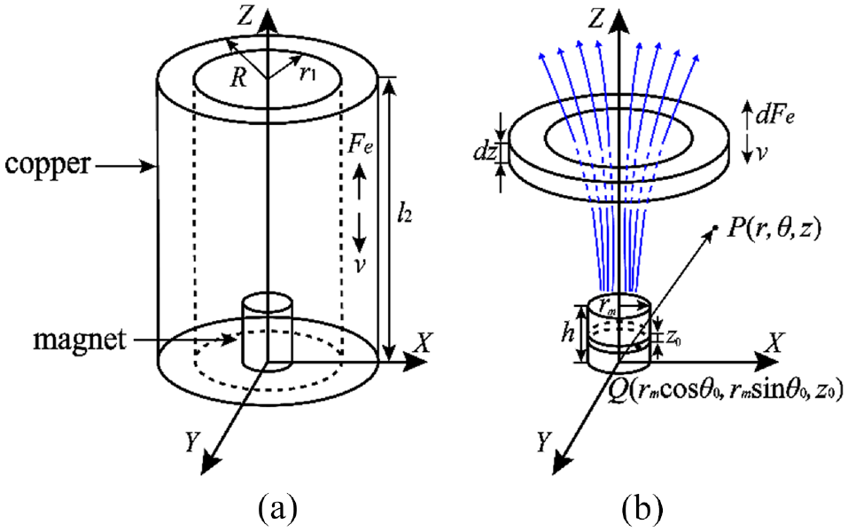
Magnetic force generated by the motion of a conductor in the magnetic field of a columnar magnet:(a) motion of the copper in the magnet field and (b) magnetic force on a differential element.
where rm is the radius, M is the magnetization of the cylindrical magnet, dz0 is the thickness of the molecular current, and μ0 is permeability of vacuum.
For a magnet with height h, the magnetic induction intensity
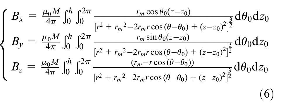
According to Lenz Law and the Left-hand Rule, Bz does not contribute to the eddy current damping when the mass moves along the z-axis. Then the magnetic flux passing through the differential element can be obtained as equation (7).
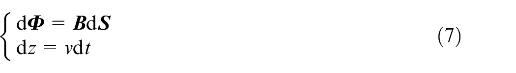
where d
The eddy current damping force dFe on a differential element dz of the conductor (Figure 2(b)) is formulated as equation (8) and its direction is along the z-axis.
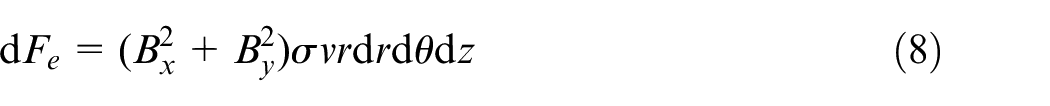
where σ is the conductivity of copper.
Finally, the total eddy current damping coefficient ce of the damper can be obtained after integrating the eddy current damping force dFe along the height of the copper (equation (9)).
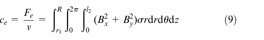
where r1 is the inner diameter and R is the outer diameter of the copper.
Geometry design of the damper
Geometric parameter determination
The dynamic model of a thin-walled part with a viscous damper is represented as a two-DOF vibration system (Figure 3). The equivalent viscous damping coefficient cv of the damper is calculated by summing the air damping coefficient ca and eddy current damping coefficient ce (equation (10)).

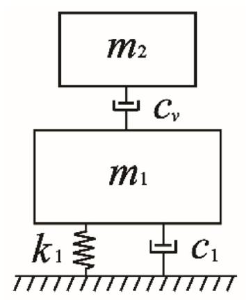
Dynamic model of the thin-walled part with viscous damper.
The critical depth of cut of thin-walled part milling can be calculated by equation (11) 25 as the cutting tool is much stiffer.
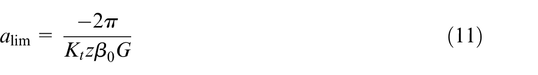
where alim is the critical depth of cut, Kt is the tangential cutting force coefficient, Z is the number of teeth of a cutting tool, and β0 is the directional factor. G is the real part of the frequency response function of the thin-walled part with the damper.
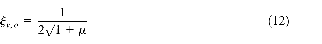
When the damping coefficient c1 of the thin-walled part is neglected as it is low in most cases, the optimal damping ratio ξv, o of the composite viscous damper for maximizing the critical depth of cut is given as equation (12). 21
Therefore, the optimal equivalent damping coefficient cv, o of the composite viscous damper is formulated with the damper geometries (equation (13)).
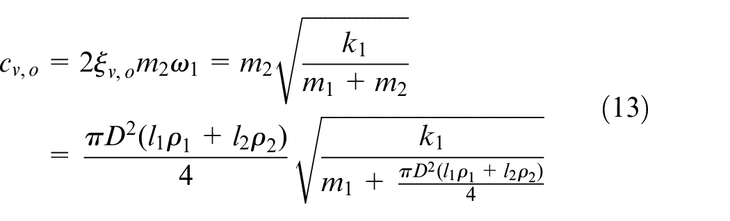
where k1 is the stiffness of the thin-walled part, ρ1 and ρ2 are density of the wolfram and copper respectively.
As the air damping coefficient ca and eddy current damping coefficient ce are dependent with the diameter D and copper length l2, the relationship among the equivalent viscous damping cv, diameter D, and copper length l2 are investigated. The equivalent viscous damping cv increases with the length l2 and diameter D for l1 = 13 mm and M = 3e6 A/m (Figure 4). Specifically, the equivalent viscous damping cv varying with the length l2 and the diameter D are plotted in Figure 5. It is seen that it is more sensitive to the variation of diameter D than that of the length l2.
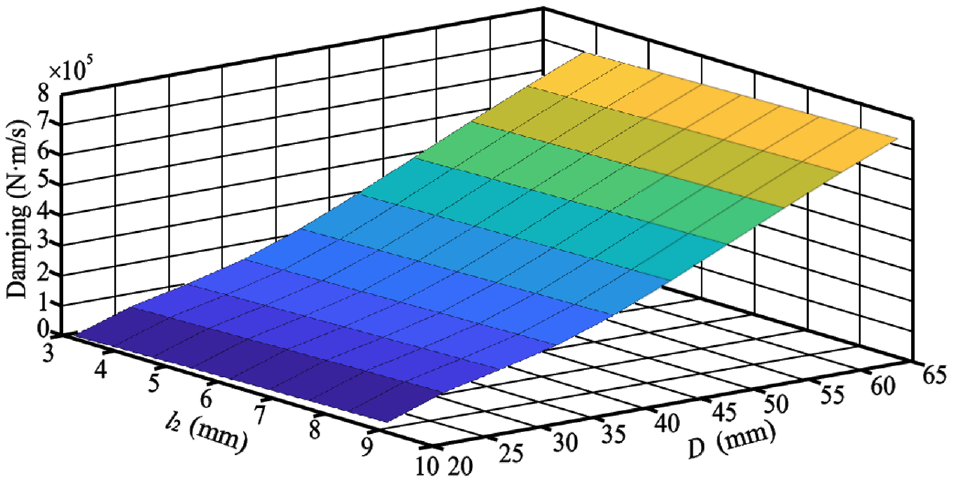
The equivalent damping varying with the length l2 and diameter D for M = 3e6 A/m.
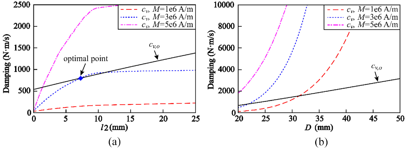
The relationship between the equivalent viscous damping, optimal damping, and geometries of the damper: (a) D = 20 mm and (b) l2 = 5 mm.
For an aluminum 7075 cylindrical thin-walled part (Figure 6(b)), with inner diameter 300 mm, height 60 mm, and wall thickness 8 mm, the optimal equivalent viscous damping coefficient cv, o is plotted in Figure 5. According to equations (10) and (11), the intersection points of the cv and cv, o correspond to the optimal geometries of the composite viscous damper.
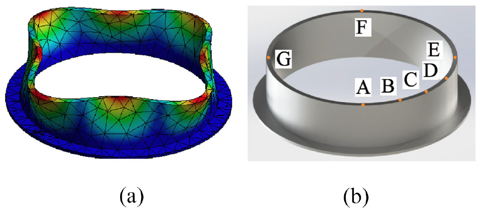
Geometrical model of the thin-walled part: (a) the first mode shape and (b) the test points.
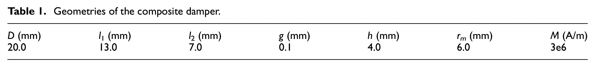
Meanwhile, the diameter D and length l1 are selected as 20 and 13 mm respectively considering the restriction on the working space of the damper. The magnet is purchased from commercial products, and the radius rm, height h, and magnetization M are given as 6 mm, 4 mm, and 3e6 A/m respectively. The length l2 is selected as 7 mm according to the optimum point in Figure 5(a). Finally, the gap g is calculated as 0.1 mm by equation (4). The geometries of the damper for the cylindrical thin-walled part are given in Table 1.
Geometries of the composite damper.
Numerical simulation
According to the finite element simulation, the first mode shape of the thin-walled part demonstrates that the maximum vibration amplitude is located at eight points, among which four points (i.e. A, E, F, G) distributed symmetrically with 90° interval are vibrating with the same phase (Figure 6(a)). Therefore, due to the symmetry of the cylindrical thin-walled part, four Points A, B, C, and D with 90° circumferential interval are tested to locate the point with maximum vibration amplitude (Figure 6(b)). Figure 7 shows the corresponding drive point FRFs, and it can be seen that Point A has the largest vibration amplitude at the first mode of 1595 Hz.
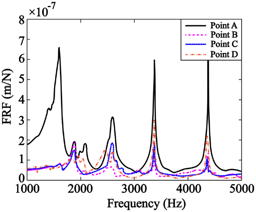
The FRFs of the thin-walled part at different points.
In order to evaluate the optimal selection of geometrical parameters (i.e. l1, l2, D), the damping behaviors of the composite viscous damper are simulated by employing the receptance coupling method 15 (equation (14)).
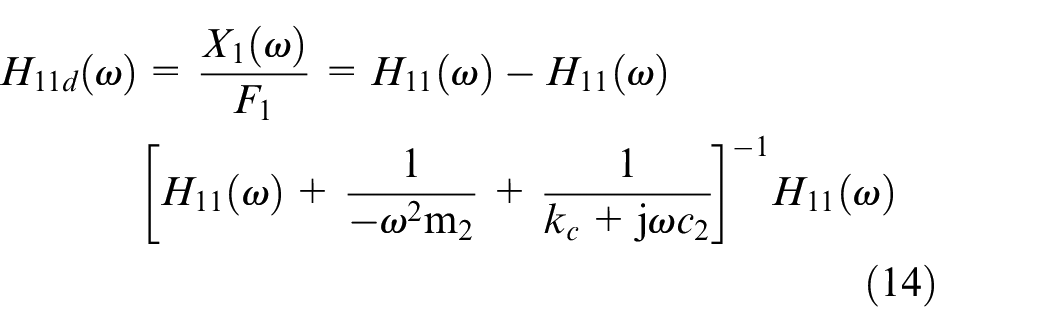
where H11(ω) is the FRF of the workpiece before damping. kc is the connection stiffness between the workpiece and the damper, which is zero for composite viscous damper theoretically.
The damper mass m2 is kept constant and equal to the physical mass of the workpiece to ensure a fair comparison. Considering the case when the damper is mounted at Point A, the simulation (Figure 8) indicates that the damper can suppress all modes of the thin-walled part. The FRF amplitude at the first mode is reduced by 60% for optimal selection of l1 = 13 mm, l2 = 7 mm, and D = 20 mm, which achieves the largest amplitude reduction compared to that of the damper with different dimensions.
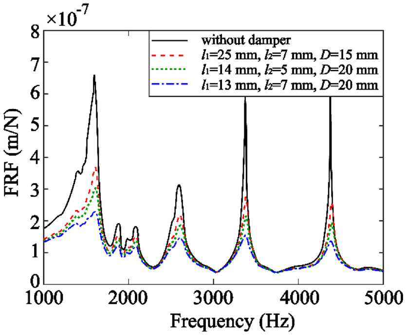
The simulated FRFs of the thin-walled part equipped with the damper of different geometries.
Experimental verification
Modal test
The modal test is performed on the thin-walled cylindrical part to verify the damping performance of the designed damper. An impact hammer PCB 086C03 with a sensitive 2.25 mV/N and an accelerometer 8778 A500 with a sensitivity of 10.49 mV/g are employed. The signals are fed to the data acquisition card NI 9234 and processed by CutPro V9.3 software.
In order to achieve optimal vibration suppression, the damper is desired to be mounted at the position with the maximum vibration amplitude. Therefore, the Points A, E, F, and G are selected for mounting the dampers in milling tests, according to the finite element simulation (Figure 6(b)).
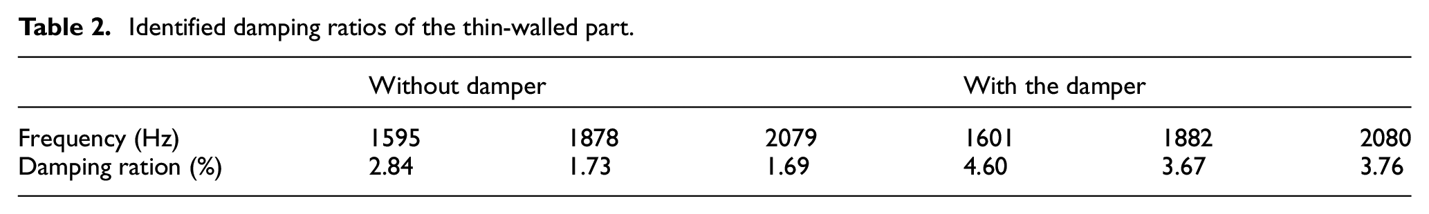
Multiple modes of the thin-walled part are effectively suppressed after mounting the composite viscous damper at the Point A (Figure 9), and the amplitude of the first mode is reduced by 57%, which agrees with the simulation result of 60%. The damping ratios of the first three modes are improved from 2.84%, 1.73%, and 1.69% to 4.60%, 3.67%, and 3.76% after modal parameter identification, respectively (Table 2). Meanwhile, the natural frequency of the thin-walled part is shifted from 1595, 1870, and 2079 Hz to 1601, 1882, and 2080 Hz due to the increase of dynamic stiffness.
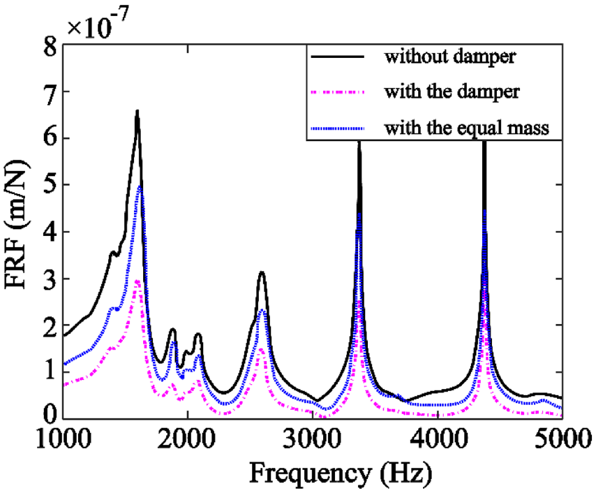
The comparison of vibration suppression between the damper and equal mass.
Identified damping ratios of the thin-walled part.
Furthermore, the introduction of the composite viscous damper on the thin-walled part increases the equivalent damping and mass, both of which are beneficial to vibration suppression. In order to identify the contribution of viscous damping, the damper is replaced with an equal mass, and the FRF of the thin-walled part is measured. The first mode of the thin-walled part is reduced by 25% after mounting the mass block, as can be seen in Figure 9. According to the comparison, the viscous damping contributes 32% of the vibration suppression.
Milling tests
The machining tests are carried out by down milling the thin-walled part (Figure 10) on a three-axis vertical CNC milling machine BV100. A three-tooth end mill with a diameter of 10 mm is selected. The feed rate F and the radial depth of cut ae are selected as 800 mm/min and 1.0 mm, respectively. The vibration signals of the thin-walled part are collected during the machining tests.
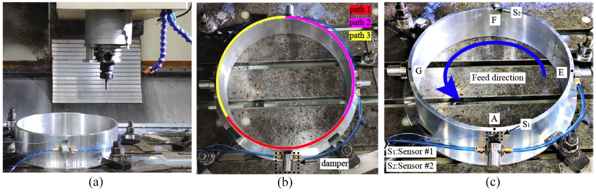
The setup of milling tests: (a) experimental setup, (b) Scenario 1, and (c) Scenario 2.
Scenario 1: Mitigation of the chatter vibration
For the tangential cutting force coefficient K tc = 959 N/mm2 and radial force coefficient K rc = 433 N/mm2, the stability lobes of the thin-walled part are predicted in Figure 11. The minimum critical depth of cut is increased from 1.3 to 2.6 mm after mounting the damper.
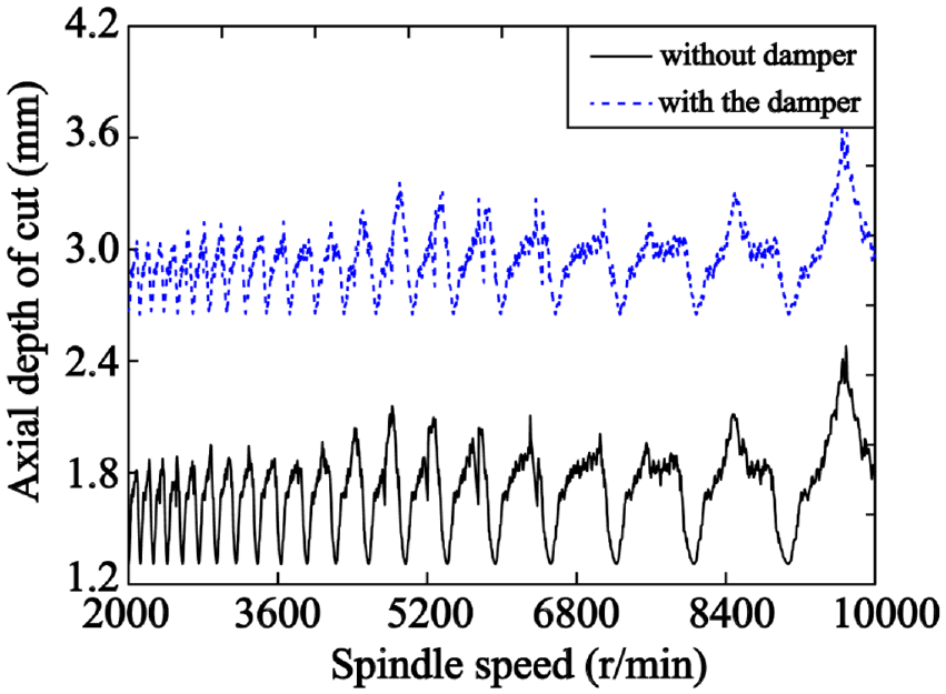
Stability charts of the thin-walled part before and after mounting the damper.
The cutting path on the workpiece is divided into three identical paths (path 1, 2, and 3) with 120° interval to ensure that the machining vibration along theses paths is fairly compared (Figure 10(a)). Path 1 is machined without damper, path 2 is machined with single damper mounted at Point E, and path 3 is machined with four dampers mounted at the Points A, E, F, and G (Figure 6(b)). Two configurations of cutting parameters are selected to verify the suppression of chatter vibration.
The vibration amplitude of the thin-walled part is reduced from 29 to 13 g (Figure 12) after mounting single damper for the spindle speed n = 5000 r/min and the cutting depth a p = 2.5 mm, accounting for a 55% amplitude reduction. With the vibration signal transformed to the frequency domain, the harmonics at 1610, 1750, 1833, and 1917 Hz are observed. The frequency 1610 Hz is close to the natural frequency 1601 Hz of the thin-walled part; therefore, it is identified as the chatter frequency. The multiple harmonics of the spindle rotating frequency of 83 Hz are 1750, 1833, and 1917 Hz. The harmonics at 1610 Hz and the spindle rotating frequency are reduced after mounting the damper. As a result, the cutting process tends to be stable after employing the damper. After mounting four dampers, the machining vibration amplitude of the thin-walled part is further dropped to 7 g (Figure 12(c)), which accounts for 21% reduction compared with the case of employing single damper, resulting in a further reduction of the harmonics 1610 Hz and the spindle rotating frequency in the frequency domain.
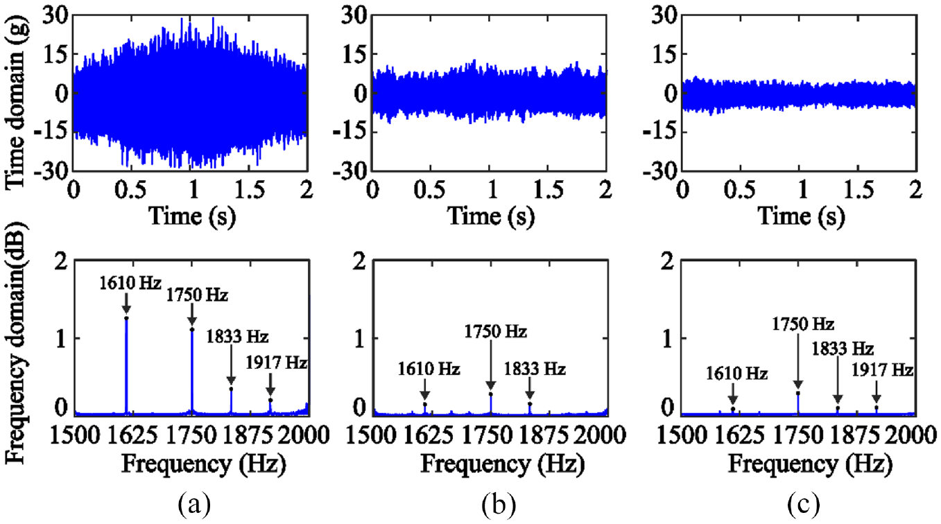
The machining vibration of Scenario 1 when n = 5000 r/min and a p = 2.5 mm: (a) without damper, (b) with single damper, and (c) with four dampers.
For the spindle speed n = 2400 r/min and the cutting depth a p = 1.5 mm (Figure 13), the vibration is decreased from 30 to 14 g after attaching single damper, and is further dropped to 8 g after mounting four dampers. After transforming the vibration signal to the frequency domain, it is observed that the chatter frequency 1614 Hz and the harmonic frequency 1920 Hz of tooth passing frequency are suppressed after mounting damper.
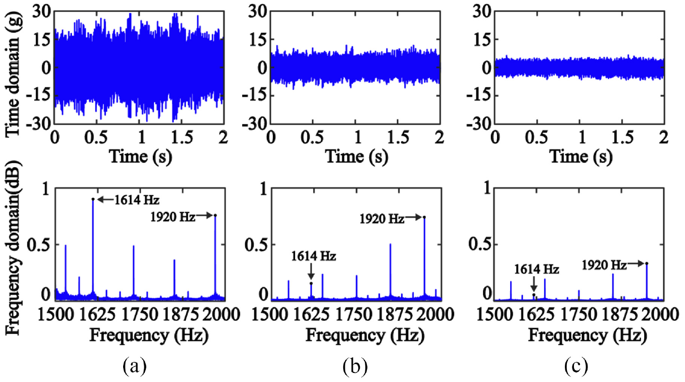
The machining vibration of Scenario 1 when n = 2400 r/min and a p = 1.5 mm: (a) without damper, (b) with single damper, and (c) with four dampers.
Scenario 2: Mitigation of the resonant vibration
The suppression of resonant vibration is verified in Scenario 2 by keeping the four dampers mounted at the Points A, E, F, and G, respectively (Figure 10(b)). Starting from the point E, the machining process is performed on the inner side of the thin-walled part in a counterclockwise direction. For exciting resonant vibration, the frequency of the milling force is set to be the same as the natural frequency of the thin-walled part. During the milling tests, two accelerometers 8778 A500 are utilized and attached to Points A (S1) and F (S2) to collect the vibration of the thin-walled part (Figure 11). The spindle speed is set as 4000 r/min in accordance with the natural frequency of first mode, 1601 Hz. The cutting depth ap of 2.0 mm is employed.
The cutting tool passes the Points F and A during the time interval t1 and t2, respectively. For the undamped case, the maximum vibration amplitudes of the Sensor #1 and Sensor #2 are 22 and 13 g during t1, and are measured as 12 and 24 g during t2 (Figure 14(a) and (c)). With the dampers employed, the maximum vibration amplitudes measured by Sensor #1 and Sensor #2 are reduced to 8 and 6 g during t1, and are reduced to 7 and 8 g during t2 (Figure 14(b) and (d)).
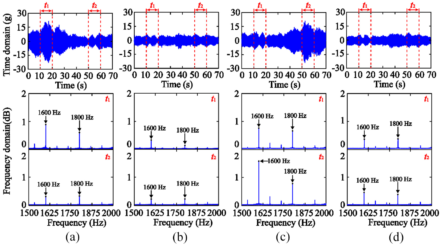
The machining vibration of Scenario 2 with n = 4000 r/min and ap = 2.0 mm: (a) without damper, Sensor #1, (b) with four dampers, Sensor #1, (c) without damper, Sensor #2, and (d) with four dampers, Sensor #2.
Fast Fourier transformation is performed within the time interval t1 and t2 respectively. Both the harmonics 1600 and 1800 Hz are the multiple integers of the tooth passing frequency 200 Hz. It can be seen that the harmonics 1600 and 1800 Hz of the time interval t1 and t2 are significantly decreased after mounting four dampers. The results indicate that the resonant vibration in machining process of the thin-walled part is suppressed effectively.
Conclusions
A composite viscous damper including air damping and eddy current damping is designed for improving the damping efficiency. The damper is applied to suppress multiple vibration modes of a cylindrical thin-walled part during machining.
Based on the formulations of the air damping and eddy current damping, the optimal equivalent viscous damping is obtained for maximizing critical depth of cut. Afterward, the geometries of the damper are determined for an aluminum alloy cylindrical thin-walled part. The damping behaviors of the damper are predicted in numerical simulations based on the receptance coupling method.
By using finite element simulation, the mounting positions of the damper with maximum vibration amplitude are determined based on the mode shape of the thin-walled part. Modal test shows that multiple vibration modes of the thin-walled part are suppressed and a maximum 57% amplitude reduction of the FRF is achieved after employing single damper. The damping ratios of the first three modes are increased significantly. The damping of the composite viscous damper contributes to 32% of the vibration suppression, according to the comparison between the damper and the block with equal mass.
The composite viscous damper is applied to suppress the chatter vibration and resonant vibration when machining a thin-walled part. The critical depth of cut is increased about two times by the damper, and the machining vibration is reduced by 55% and 76% after mounting single damper and four dampers, respectively.
The damping efficiency could be further promoted by replacing the air medium with the fluid. However, as the dynamic viscosity increases, the generation of the relative motion may require a larger vibration amplitude in order to generate a larger inertial force. Furthermore, the employment of fluid medium may cause the increase of the gap between the mass and shell, making the formulation based on the assumption of a concentric ring inapplicable. In this case, the effect of eccentricity should be considered in the formulation of flow rate in the gap.
Footnotes
Appendix
Declaration of conflicting interests
The author(s) declared no potential conflicts of interest with respect to the research, authorship, and/or publication of this article.
Funding
The author(s) disclosed receipt of the following financial support for the research, authorship, and/or publication of this article: This work is supported by the National Natural Science Foundation of China (Grant No. 91960108 and 51675032).