
Abstract
Nonlinearities have been evidenced during the chatter vibration of milling. Machinability of the thin-walled part is feed rate and position-dependent, and is subject to process damping at low cutting speed. Therefore, chatter stability prediction of milling considering nonlinear cutting force, nonlinear structural stiffness and process damping is investigated. The cutting force and stiffness are established based on the polynomial model and the process damping is investigated based on the dissipated energy. The dynamic cutting force and stability lobes are solved in the time domain with coefficients updated at each iteration. By formulating the displacement as an expanded form via the perturbation method, the time-consuming solution of delay differential equations is avoided. After formulating the identification of the nonlinear model via cutting tests and modal tests, numerical simulations considering nonlinearities are carried out and compared with the analytical method. The proposed method attains high accuracy of classic time-domain solution, but with an improved computational efficiency. Finally, cutting tests are conducted to verify the prediction of cutting force and stability lobes.
Introduction
Chatter vibration is apt to occur during the milling process of thin-walled workpiece, which reduces machining efficiency and deteriorates workpiece surface. Many strategies for chatter avoidance have been proposed, such as cutting process optimization, structural dynamics modification through passive and active control. Si and Wang 1 presented an iterative compensation strategy to reduce the tool/workpiece deformation-induced surface error during the five-axis flank milling of thin-walled workpiece. Liu et al. 2 proposed a tool inclination method based on the adaption of the cutting force component to guarantee the machined surface finish of the thin-walled workpiece. Especially, cutting parameter optimization through the stability lobes is an efficient method and has been widely employed in the industry. 3
The chatter stability prediction based on linear model achieves high accuracy for most cases. However, nonlinearities have been evidenced during the milling process. The machinability is feed rate dependent while the linear cutting force model is unable to predict the effect of feed rate. Meanwhile, the machinability is changing with the tool path due to the variation of workpiece stiffness, especially for a thin-walled part. Besides, low cutting speed is usually selected during machining hard-to-cut materials, and the machining stability is quite affected due to the introduction of process damping.
A large amount of research work has been conducted to investigate the nonlinearities during the milling process. The cutting force models formulated in a nonlinear mathematical form are mostly investigated. Lamikiz et al. 4 presented calculation of linear, quadratic and cubic polynomial shear cutting coefficients of a ball-end cutting tool. Muñoa et al. 5 studied the stability prediction in frequency domain based on the exponential instantaneous force model and demonstrated the influence of feed rate on the stability. Guzeev and Pimenov 6 proposed a mathematical model that includes the cutting forces due to processes in the shear zone and force component due to processes at the real surface of tool. Besides, investigations into the nonlinear dynamics of the machine tool/cutter/workpiece are reported. Moradi et al. 7 investigated the nonlinear dynamics of regenerative chatter and presented an extended dynamic model of the peripheral milling process. Yang et al. 8 proposed a dynamic model for tool/workpiece assembly, and the influence of dynamic behaviours and tool feed direction were considered. Karimi and Nategh 9 developed optimal tool path and workpiece setup of a hexapod machine tool by considering the kinematics nonlinearity. Furthermore, process damping has been another important factor resulting in the nonlinear behaviours of chatter. Budak and Tunc 10 presented an identification and modelling method of process damping coefficients from chatter tests, after determining the indentation force coefficient through energy analysis. Feng et al. 11 studied the generation mechanism of process damping in the milling of thin-walled part. The current work aims to establish a nonlinear chatter model by incorporating the nonlinear cutting force, nonlinear stiffness of workpiece and process damping together. Meanwhile, the identification of the nonlinear model is presented.
The mathematical solution of chatter stability lobes has been investigated quite a lot. Dun et al. 12 proposed a numerical difference method based on Adams-Bashforth scheme and multi-modal scheme for stability prediction. Yang et al. 13 developed an efficient decomposition-condensation method to predict the in-process workpiece dynamics for chatter prediction of thin-walled structure. Li et al. 14 extended dynamic model of milling system by considering regeneration, helix angle and process damping into the high-order time domain algorithm. Song et al. 15 proposed a time-space discretization method for milling stability prediction of thin-walled component based on thin-plate theory and mode superposition principle. Sellmeier and Denkena 16 proposed a semi-discretization method considering the time dependency of the system by combining Ackermann’s method and the method of the piecewise constant subsystems. The time domain methods solve the delay differential equations directly, while the semi-discretization method utilizes a finite-dimensional transformation matrix to approximate a single-valued operator of infinite dimensions. The above numerical methods have been demonstrated as high accuracy, but low efficiency compared to the frequency domain method. Current work has devoted to solving the nonlinear problems in the prediction of milling stability. However, the introduction of the nonlinearities to the chatter model presents many difficulties. The solution is much more complicated as more parameters are related to the chatter model, and sacrifice of high order terms representing nonlinearities for the purpose of improving computational efficiency causes the reduction of accuracy.
Methods to solve nonlinearity have been presented in literature. Afazov et al. 17 solved the equation of motion by integrating numerically in the time domain using the Runge-Kutta fourth-order method, considering nonlinearities of the micro-milling cutting force. Zhou et al. 18 analysed nonlinear behaviours and developed a semi-analytic method to predict the shearing, plowing and friction forces in primary and tertiary shear zones. Moradi et al. 19 investigated the nonlinear effect of structural and cutting force, tool wear and process damping, and simulated the forced vibration in milling process via perturbation method. Olvera et al. 20 presented the stability analysis of a thin-walled workpiece by using the enhanced multistage homotopy perturbation. Urbikain et al. 21 proposed multimode analysis to predict chatter in large horizontal lathes by using the modern collocation method based on the Chebyshev polynomials. As the perturbation method is beneficial for simplifying mathematical calculation, it is employed to formulate the dynamic differential equation in current work. Afterward, the iteration method is utilized to solve stability lobes due to coefficients updating of the chatter model.
As machinability of the thin-walled part is feed rate and position-dependent, and is subject to process damping at low cutting speed, a nonlinear chatter model considering nonlinear cutting force, nonlinear stiffness and process damping is established. By formulating the displacement as an expanded form via the perturbation method, the dynamic cutting force and stability lobes are solved in the time domain with an improved computational efficiency. The remainder of the paper is organized as follows: the nonlinear chatter stability model and its solution are presented in Section 2. In Section 3, the identification procedure of the nonlinear chatter model is proposed based on the least square method. In Section 4, experiments of identifying the cutting force coefficients, stiffness coefficients and process damping coefficients are presented. In Section 5, the cutting force, vibration and chatter stability lobes are predicted and compared with the analytical method. Cutting tests are conducted in Section 6, and the paper is concluded in the end.
Theoretical formulation
Dynamic model of the milling process
Regenerative chatter vibration is easy to occur during the milling process of thin-walled part and is harmful to the machining process. As fluctuation of chip thickness is induced due to the vibration of machine tool/cutter and workpiece assembly, dynamic model of the milling process is demonstrated in Figure 1.
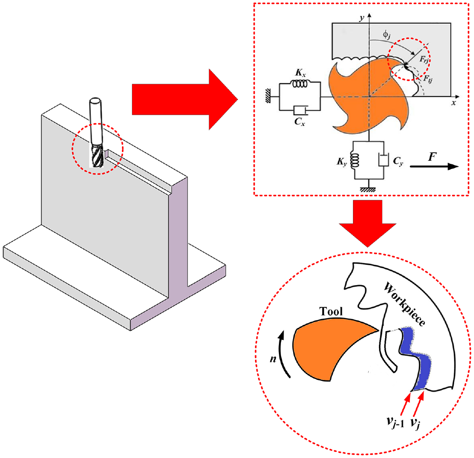
Dynamic model of the milling process of thin-walled part.
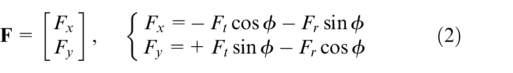
Dynamic differential equations of the milling process can be established in x and y directions as equation (1).

where
ϕ is the immersion angle (Figure 1). For a discretized cutting flute, it is
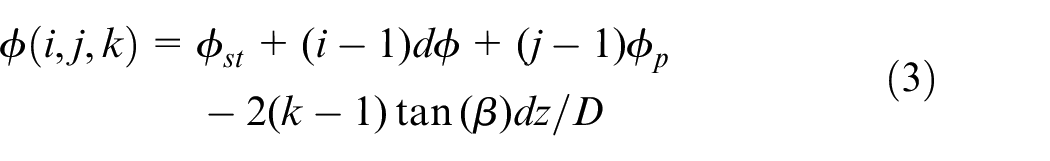
where ϕst is the entry angle, ϕp is the pitch angle, D is the diameter of cutter and β is the helix angle. i, j and k are increments denoting the time, tooth and axial depth.
In order to incorporate the nonlinear influence of feed rate on cutting force, Ft and Fr are expressed in a polynomial form as equation (4).
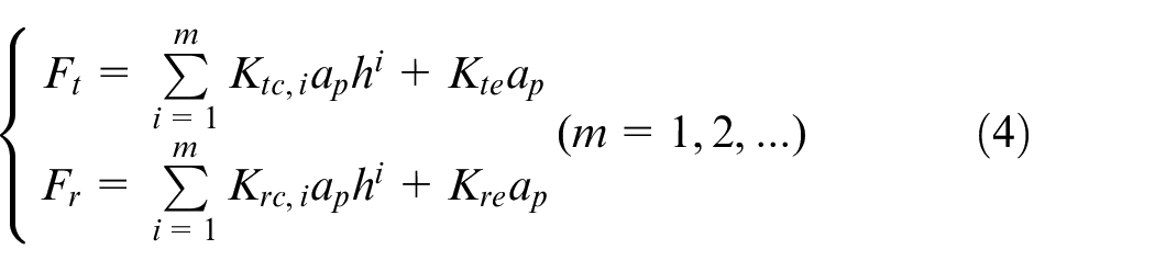
where Ktc,i and Krc,i are the tangential and radial cutting force coefficients, Kte and Kre are edge constants. ap is the axial depth of cut. h is dynamic chip thickness and is expressed as

where h0 = csinϕ corresponds to static part of the chip thickness, and c is the feed rate per tooth. Δυ is the regenerative chip thickness, and Δx and Δy are the fluctuations of chip thickness in x and y directions.
According to equations (2)–(5), Fx and Fy can be rewritten as equation (6) when m = 3 (equation (4)). A detailed formulation of coefficients μ11,
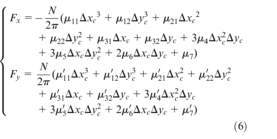
where Δxc = (c+Δx)sinϕ and Δyc = Δycosϕ are the chip thickness components. Meanwhile, the stiffness of thin-walled workpiece is established based on the polynomials as it varies with the tool path. Then, the stiffness matrix
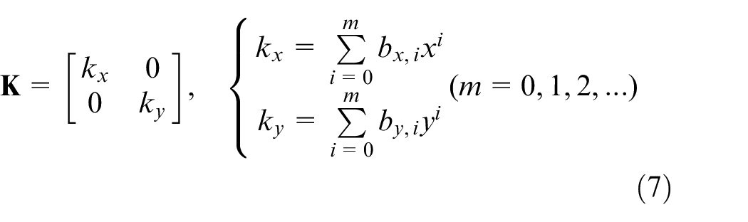
where bx,i and by,i are stiffness coefficients in x and y directions respectively.
The process damping is generated due to the contact between the wavy surface finish and round edge of the cutter, and it is dominant at low spindle speed. The tangential and radial process damping force is written as equation (8)) according to Jin and Altintas. 22
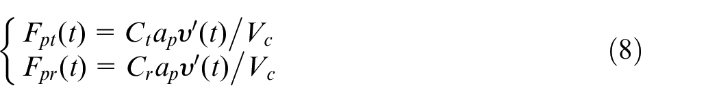
where Ct and Cr are the process damping coefficients, υ′(t) is the vibration velocity along the direction of chip thickness and Vc is the cutting speed.
By moving the term of process damping to the left side of equation (1), the damping matrix

where C0x and C0y are the inherent damping which can be obtained via modal tests.
Prediction of chatter stability
The dynamic cutting force, vibration and chatter stability lobes during the milling process of thin-walled part are predicted in time domain with coefficients updated at each iteration, enabling the simulation of entire tool path. As the introduction of high order polynomials to represent nonlinearities complicates the mathematical modelling and solution of chatter stability, the perturbation method is employed to formulate the displacement as an expanded form for the purpose of improving computational efficiency. According to the perturbation method, an approximate analytical solution of displacement x and y (equation (1)) can be formulated as equation (10).
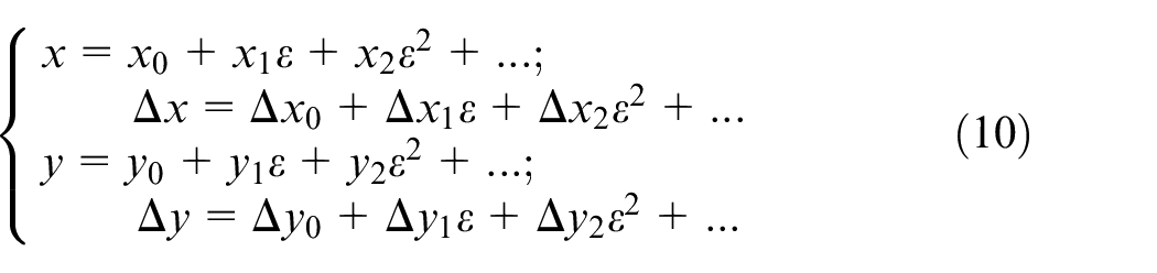
where Δxj = xj(t)−xj(t−T) and Δyj = yj(t)−yj(t−T) (j = 0, 1, 2, …). ε is the perturbation coefficient, and T is the tooth period.
Then equation (1) is rewritten in Appendix 2 according to the order of ε. For the simplification of the solution, only the zero and first orders are remained. The solution of x0, y0, x1, y1 is given in equation (11) based on the Euler formula.
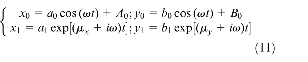
where ω is angular velocity of the spindle. According to the initial condition

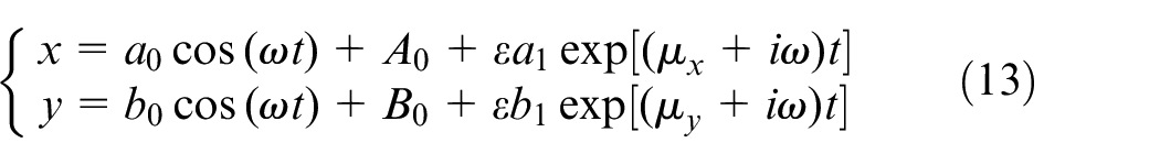
And, it is derived as A0+a0+a1 = 0 and B0+b0+b1 = 0. The a0, b0, A0, B0, a1, b1 are solved in Appendix 3 according to the Taylor series expansion. Similarly, μx and μy can be solved. Finally, an approximate solution of x and y is shown as equation (13).
As a result, the cutting force and vibration can be solved, and stability lobes are plotted by determining whether the process is unstable (Figure 2).
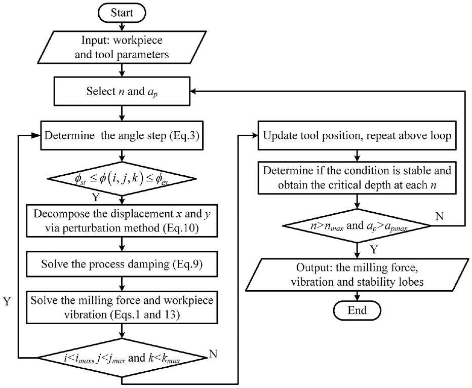
Flow chart of chatter stability prediction.
Formulation of coefficients identification
Cutting force coefficients
The cutting force coefficients are identified during a stable cutting when the fluctuation of the chip thickness has little influence on cutting force and can be ignored. The instantaneous cutting force Fx/Fy/Fz is expanded to mth order polynomial of static chip thickness h0 as equation (14).
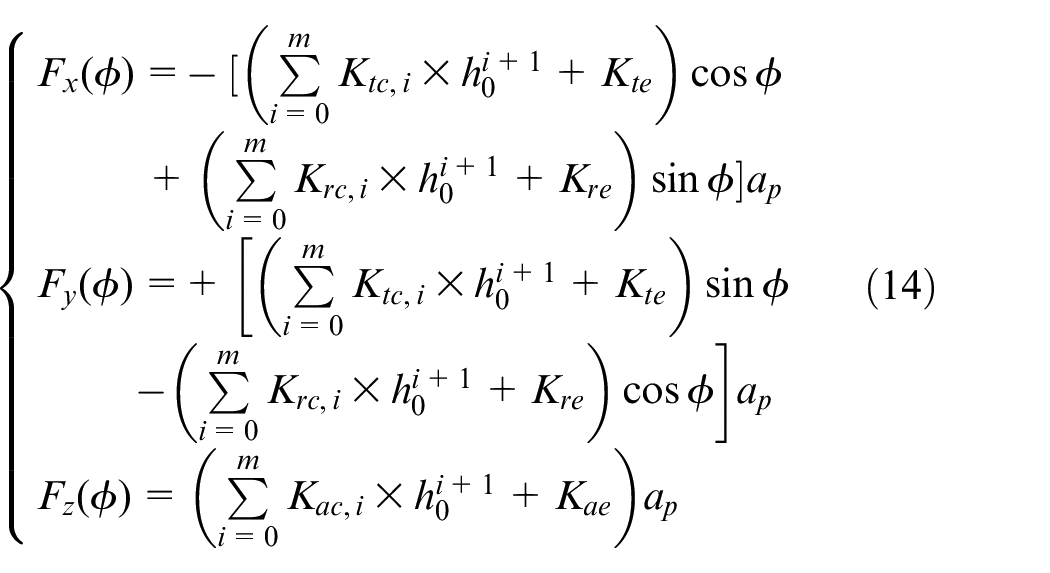
The resultant force can be calculated by the superposition of Fx(ϕ), Fy(ϕ) and Fz(ϕ), and the average cutting force
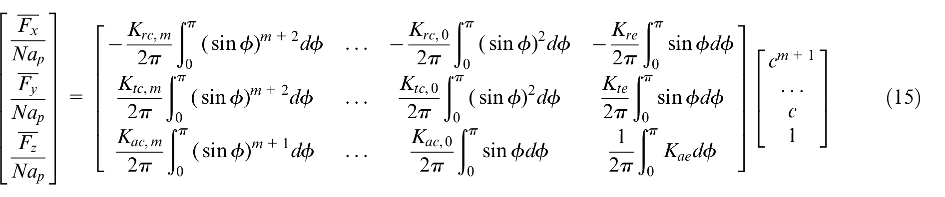
The identification algorithm of cutting force coefficients is provided in Appendix 4, and the identified coefficients when m is even (equation (16)) and odd (equation (17)) are presented as follows.
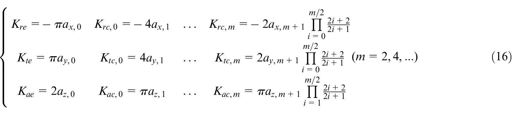
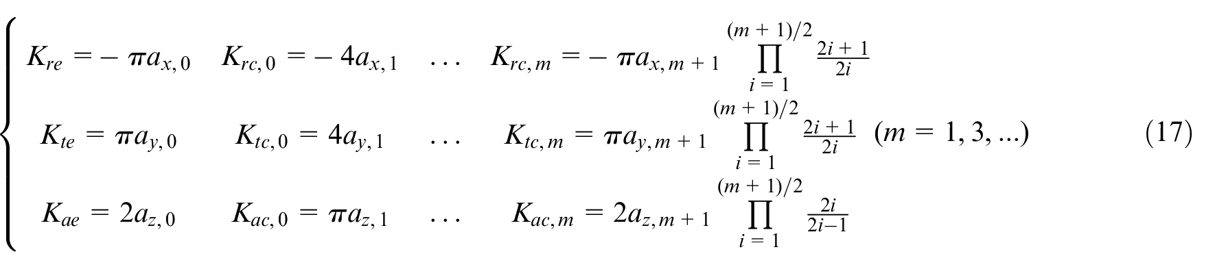
where coefficients ax,i, ay,i and az,i (i=1, …, m) are identified with the least square method.
Stiffness coefficients
As the stiffness of thin-walled part is dependent on the position, the stiffness vector, that is in x direction, is

where kxi denotes the stiffness at points xi. The vector of stiffness coefficients is

Then equation (20) is formulated based on the least square method.

where
By substituting the stiffness identified via modal tests into above equation, the coefficients vector
Process damping coefficients
The process damping coefficients Ct and Cr are identified from the dissipated energy as 22
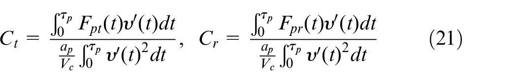
τp is the vibration period. The integration terms can be replaced by the summation of discrete sampling points via experiments. Among the components (i.e. static force, dynamic force due to regenerative effect and process damping force) of cutting force, the process damping force is effective at low cutting speed. Therefore, Fpt and Fpr can be estimated by the experimental force and theoretical force (equation (4)) calculated by cutting force coefficients identified at high cutting speed. The vibration velocity υ′ can be obtained by the vibration of thin-walled part in x and y directions according to equation (5).
Experimental identification of coefficients
Identification of cutting force coefficients
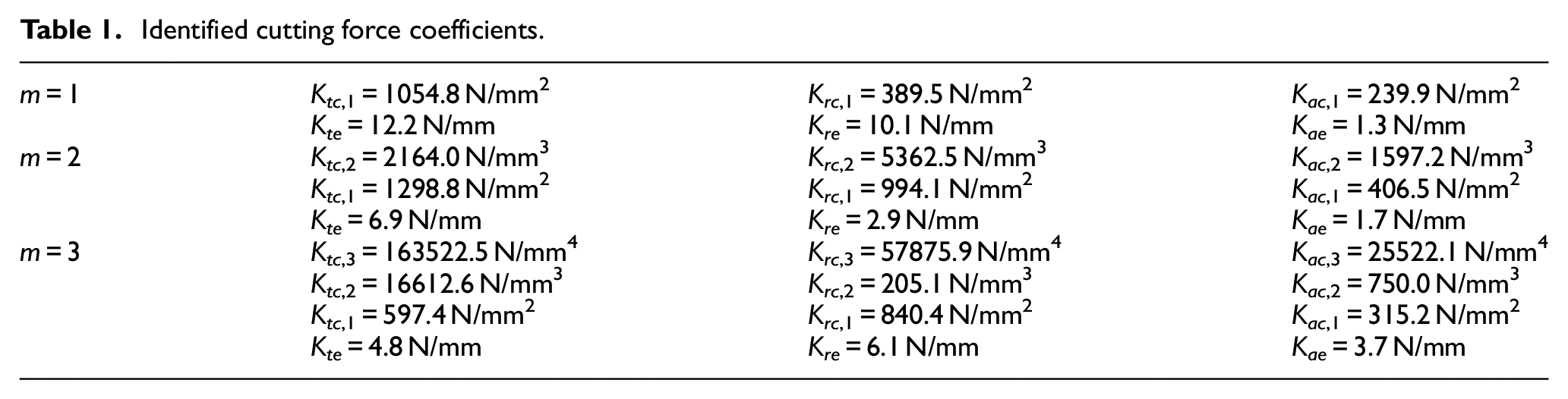
Milling tests are conducted to identify the cutting force coefficients on a machining centre of DMG DMC 635V. A carbide end mill with diameter D = 12 mm, number of teeth N = 3 and helix angle β = 30° is used. The workpiece is Aluminum alloy 7075. The spindle speed n is selected as 3000 rpm while the axial depth of cut ap is 0.5 mm, 1.0 mm, 1.5 mm and feed rate per tooth c is 0.033 mm, 0.067 mm, 0.010 mm. The cutting force Fx, Fy and Fz are measured by the dynamometer Kistler 9257B. The cutting force coefficients based on the polynomials are identified in Table 1, according to equations (16) and (17).
Identified cutting force coefficients.
Identification of stiffness coefficients
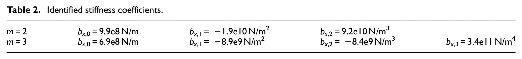
Modal tests are utilized to identify the changing stiffness of thin-walled workpiece at different positions. The impact damper PCB 086C03 with a sensitivity of 2.25 mV/N, accelerometer PCB 352A21 with a sensitivity of 106.17 mV/g and data acquisition card NI 9234 are used. Only the stiffness in x direction is identified in current work due to its flexibility compared to y direction. The stiffness at Points A, B, C and D (Figure 3) are 8.5e7 N/m, 6.3e7 N/m, 7.6e7 N/m and 9.2e7 N/m, respectively. By substituting them into equation (20), the identified stiffness coefficients (KN/m2) based on the second-order and third-order polynomials are presented in Table 2.
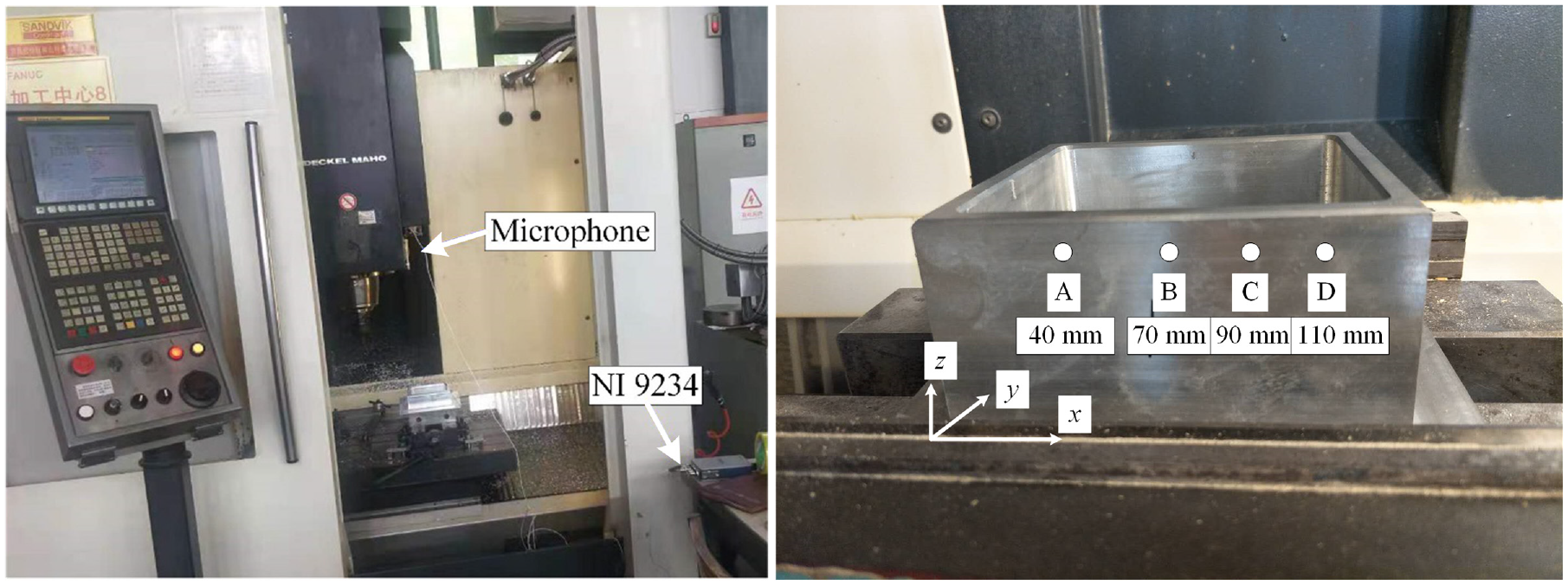
Experimental setup.
Identified stiffness coefficients.
Identification of process damping coefficients
Down milling tests are conducted to identify process damping coefficients. Three sets of parameters are utilized including axial depth of cut ap = 0.5 mm and feed rate F = 300 mm/min, ap=0.5 mm and F = 600 mm/min, ap = 1 mm and F = 300 mm/min, while spindle speed n = 3000 rpm and width of cut ae = 12 mm are kept constant. The cutting force and vibration velocity (Figure 4) in x and y directions during a single period are presented. The vibration velocity is measured by velocity sensor PCB 640B02 with a sensitivity of 0.31 mA/(mm/s). According to equation (22), the process damping coefficients are identified as Ct = 1.44e4 N/m and Cr = 3.98e4 N/m.
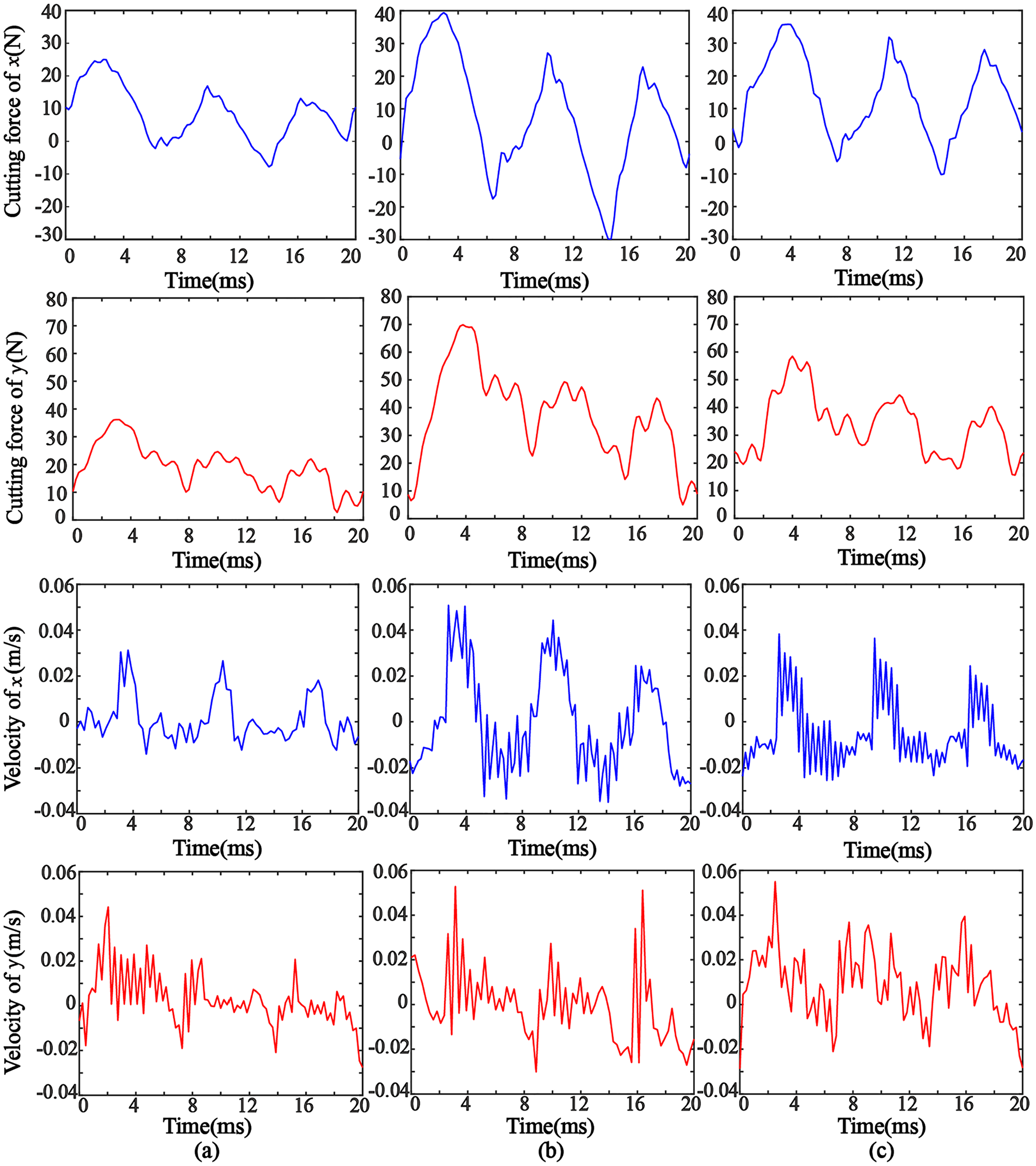
Experimental cutting force and velocity: (a) ap = 0.5 mm, F = 300 mm/min, (b) ap = 0.5 mm, F = 600 mm/min and (c) ap = 1 mm, F = 300 mm/min.
Numerical simulation
Based on the polynomial model of cutting force and stiffness, the milling force and stability lobes are predicted after identifying the coefficients, and then compared with analytical method and experiments. The cutter and workpiece are the same as above section.
Static simulation of the milling force
Three configurations of slot milling are simulated. The axial depth of cut ap and feed rate per tooth c are changed while spindle speed n is 3000 rpm. It is seen that the simulated cutting force via proposed method is approximate to the analytical method 13 and experiments with 5% difference on amplitude (Figure 5), but the computation time is much longer due to iterated solution. However, dynamic milling force and vibration are able to be simulated due to the coefficients updated during each iteration.
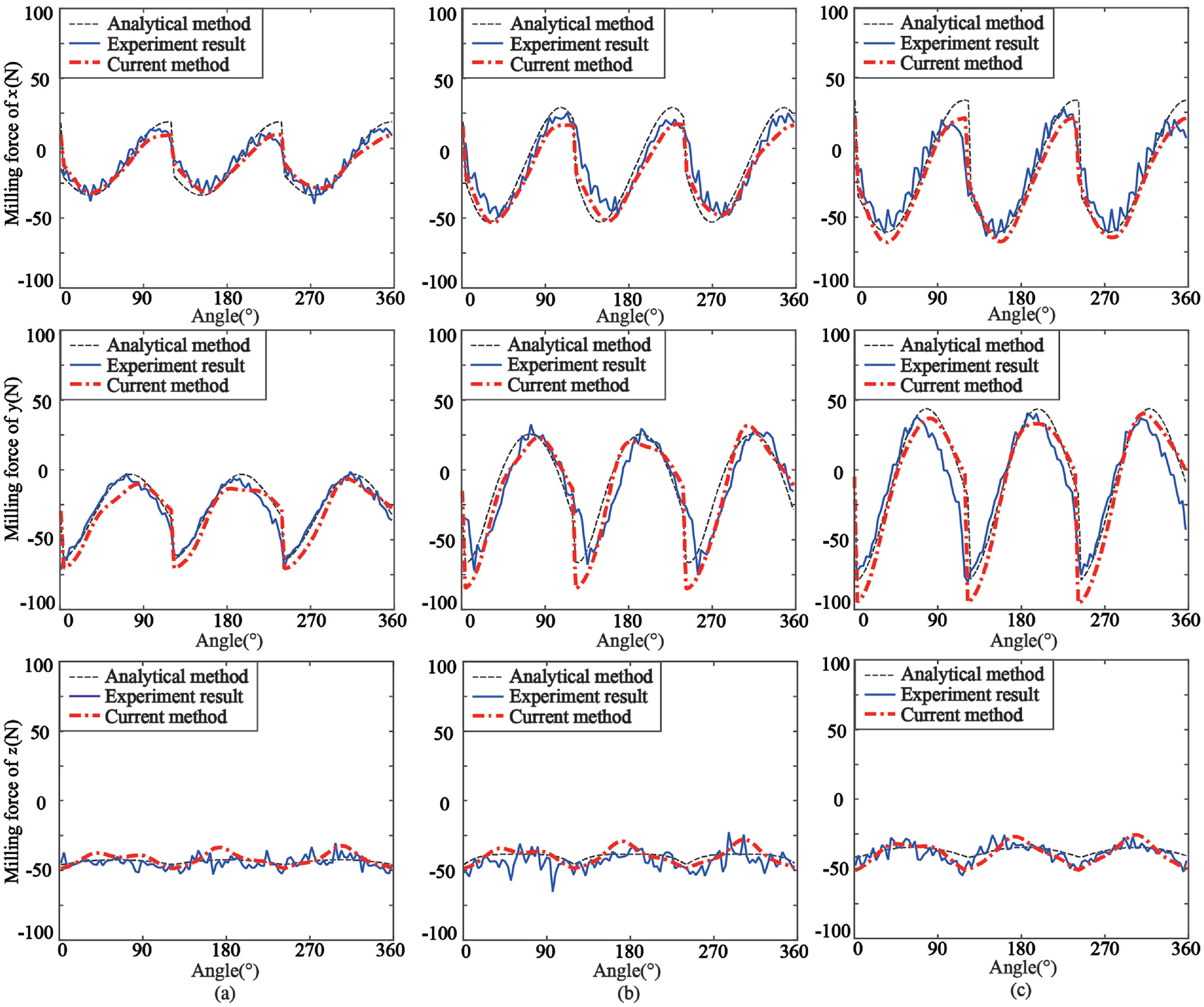
Static simulation of milling force in x, y and z directions: (a) ap = 0.5 mm, c = 0.05 mm, (b) ap = 0.5 mm, c = 0.10 mm and (c) ap = 1.0 mm, c = 0.05 mm.
Dynamic simulation of the milling force and vibration
Dynamic milling force and vibration of the thin-walled part (Figure 3) are simulated. Stiffness variation is considered to simulate actual milling process. For down milling of spindle speed n = 6000 rpm, feed rate per tooth c = 0.05 mm and width of cut ae = 4 mm, the cutting force increases from 400 N, 800 N and 1000 N to 700 N, 1400 N and 1800 N from 0.1 s to 1.0 s when ap = 4 mm, 6 mm and 8 mm (Figure 6). Meanwhile, the acceleration increases from 8 g, 10 g and 12 g to 21 g, 28 g and 42 g. The cutting force and workpiece vibration are maximum at t = 1.0 s when the tool position is located at the middle position and corresponding stiffness is the weakest. It is observed that there are 25%, 10% and 22% difference on the simulated workpiece vibration compared with experiments.
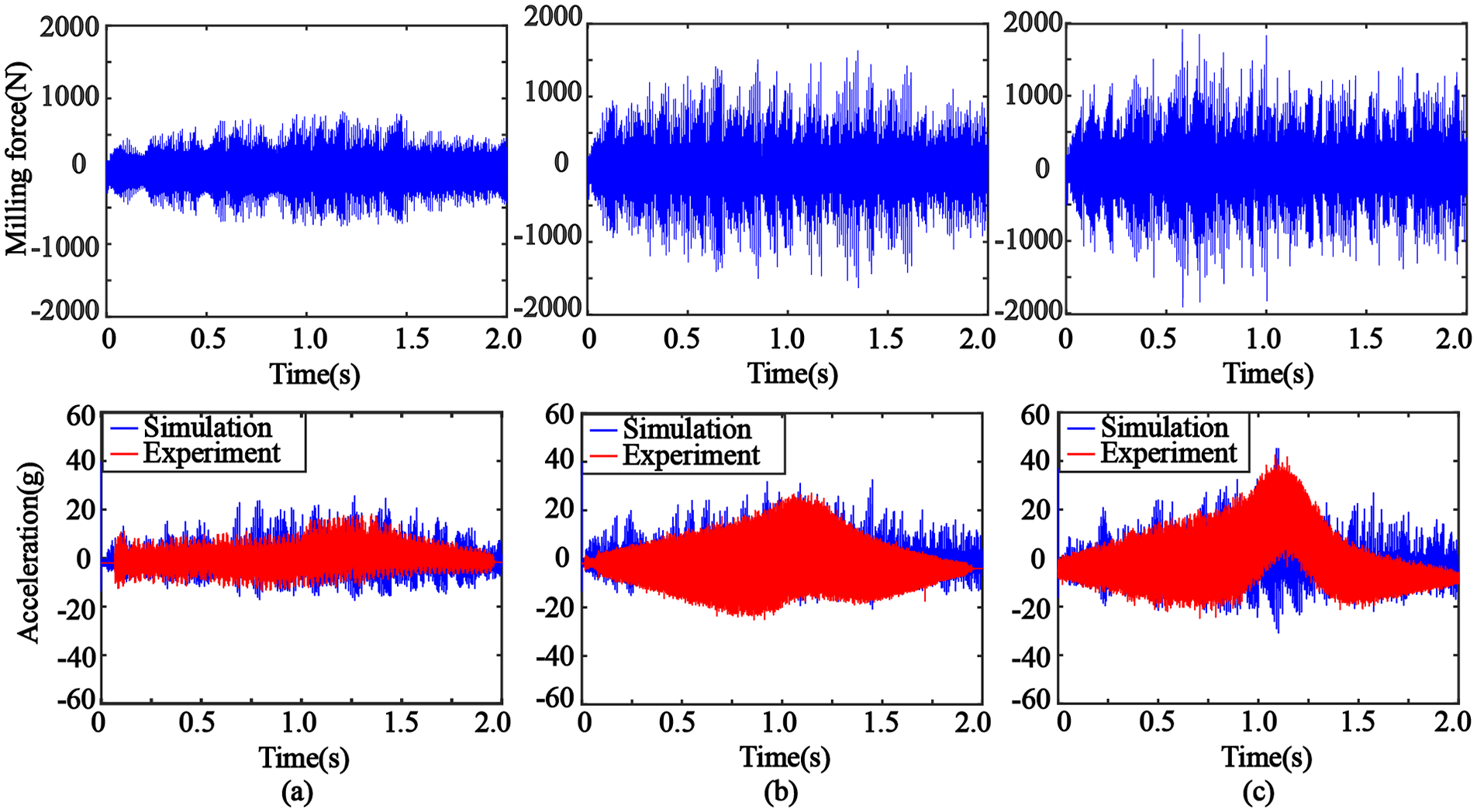
Dynamic simulation of milling force and workpiece vibration considering stiffness variation: (a) ap = 4 mm, (b) ap = 6 mm and (c) ap = 8 mm.
Prediction of stability lobes
Chatter stability simulation via the proposed method based on linear model is compared with analytical method 13 and experiments. For slot milling of the thin-walled part, the critical depth of cut is 1.6 mm (Figure 7(a)) at x = 90 mm while it is 1.4 mm and 1.5 mm for analytical and semi-discretization methods respectively. Besides, the critical depth of cut for the three methods are 1.7 mm, 1.5 mm and 1.6 mm (Figure 7(b)) when down milling with ae = 6 mm, and are 1.8 mm, 1.7 mm and 1.7 mm (Figure 7(c)) when down milling with ae = 4 mm. Simulations of the three methods are quite close.
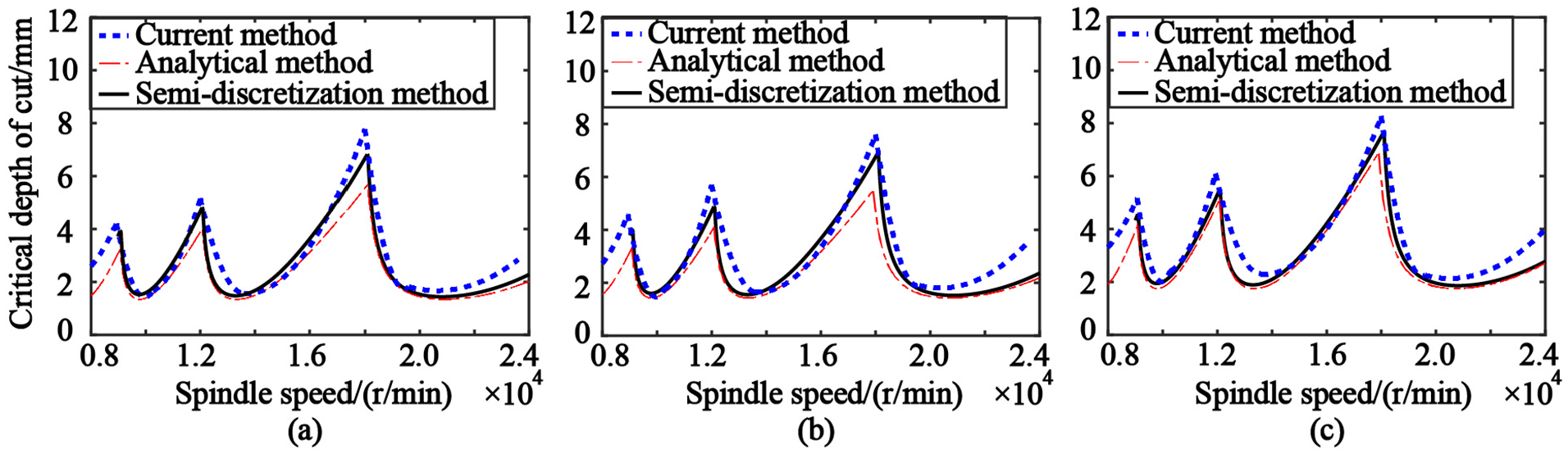
Comparison of stability lobes: (a) slot milling, (b) down milling, ae = 6 mm and (c) down milling, ae = 4 mm.
Next, chatter stability simulations based on the third-order polynomial model of cutting force are demonstrated (Figure 8). For slot milling, the critical depth of cut increases from 1.3 mm to 2.5 mm as c increases from 0.04 mm to 0.08 mm. Meanwhile, the critical depth of cut increases from 1.4 mm and 1.7 mm to 2.7 mm and 2.8 mm as c increases for down milling, ae = 6 mm and 4 mm. It is observed that c has an impact on the stability lobes, and the critical depth of cut increases as c increases.
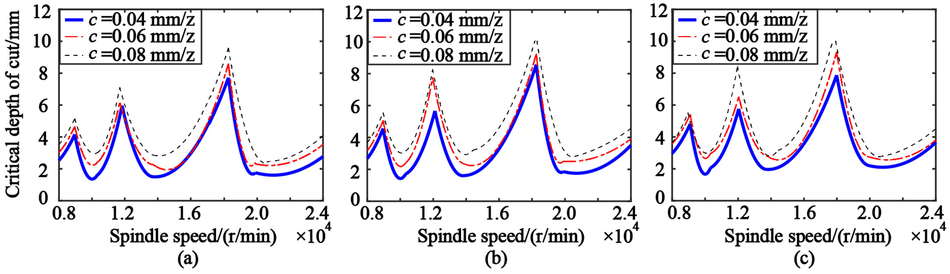
Chatter stability lobes when c = 0.04 mm, 0.06 mm and 0.08 mm: (a) slot milling, (b) down milling, ae = 6 mm and (c) down milling, ae = 4 mm.
Furthermore, the influence of nonlinear stiffness on chatter stability lobes is simulated at different tool positions. For down milling with ae = 4 mm and c = 0.05 mm, three locations indicated in Figure 3 are simulated (Figure 9(a)). The critical depth of cut is 2.4 mm at x = 40 mm (Point A), 1.7 mm at x = 70 mm (Point B) and 2.1 mm at x = 90 mm (Point C). The minimum critical depth of cut is located at x = 70 mm. Besides, the influence of process damping on chatter stability lobes is simulated for down milling, ae = 4 mm and c = 0.04 mm. For x = 90 mm, the critical depth of cut increases from 2.2 mm to 3.3 mm at n = 2200 rpm after process damping is considered (Figure 9(b)), corresponding to an increase of 60%. However, there is little difference after the spindle speed of 3800 rpm.
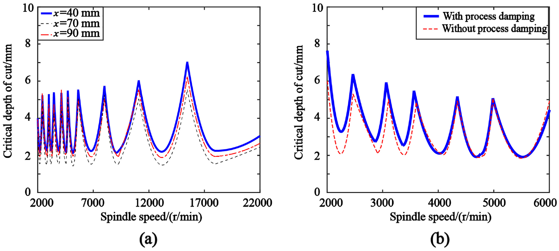
Chatter stability lobes: (a) at different tool positions and (b) without and with process damping (x = 90 mm).
Stability analysis of thin-walled part
The stability lobes of thin-walled part considering nonlinear cutting force, nonlinear stiffness and process damping for down milling, ae = 4 mm and c = 0.04 mm are illustrated in Figure 10(a), and the relation between the critical depth of cut and tool position is illustrated in Figure 10(b). Four spindle speeds are considered. The stability limit is maximum when n = 2000 rpm and is minimum when n = 8000 rpm. For n = 8000 rpm, the critical depth of cut decreases from 2.4 mm to 1.7 mm when the tool position moves from x = 40 mm to 70 mm, and increases to 2.1 mm at x = 90 mm. In order to verify the above simulation, the tool path is divided into three segments (Figure 10(b)) and corresponding machining signals are recorded. The Path I corresponds to x = 40 mm to 60 mm, the Path II corresponds to x = 60 mm to 80 mm, and the Path III corresponds to x = 80 mm to 100 mm.
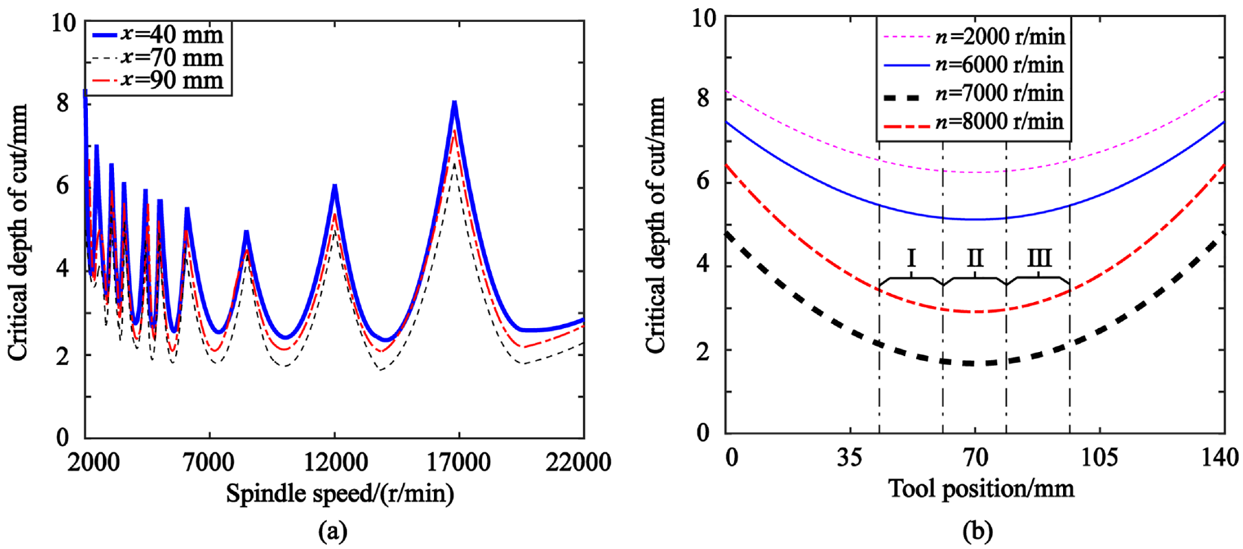
Stability lobes considering nonlinearities: (a) stability lobes at different tool positions and (b) relation between the critical depth of cut and tool positions.
Cutting tests
Down milling tests (Figure 3) are conducted to verify the above simulations. The width of cut ae = 4 mm and feed rate F = 900 mm/min are kept constant, and four configurations of the axial depth of cut ap and spindle speed n are utilized. The machining sound is collected by the microphone PCB 378B02.
When ap = 3 mm and ap = 5 mm, the maximum machining sound are 1.9 Pa (Figure 11(a)) and 2.8 Pa (Figure 11(b)) for n = 6000 rpm, and increase to 7.5 Pa (Figure 11(c)) and 9.8 Pa (Figure 11(d)) for n = 8000 rpm. The increase is quite large, and it is explained that chatter vibration occurs as can be observed from the simulation. According to the chatter stability lobes in Figure 10(b), the minimum critical depth of cut is 5.2 mm located at x = 70 mm when n= 6000 rpm, and critical depth of cut is 3.4 mm and 2.8 mm at x = 40 and 70 mm when n = 8000 rpm. Besides, it is noted that the maximum vibration occurs during path II as corresponding stiffness of thin-walled part is the weakest.
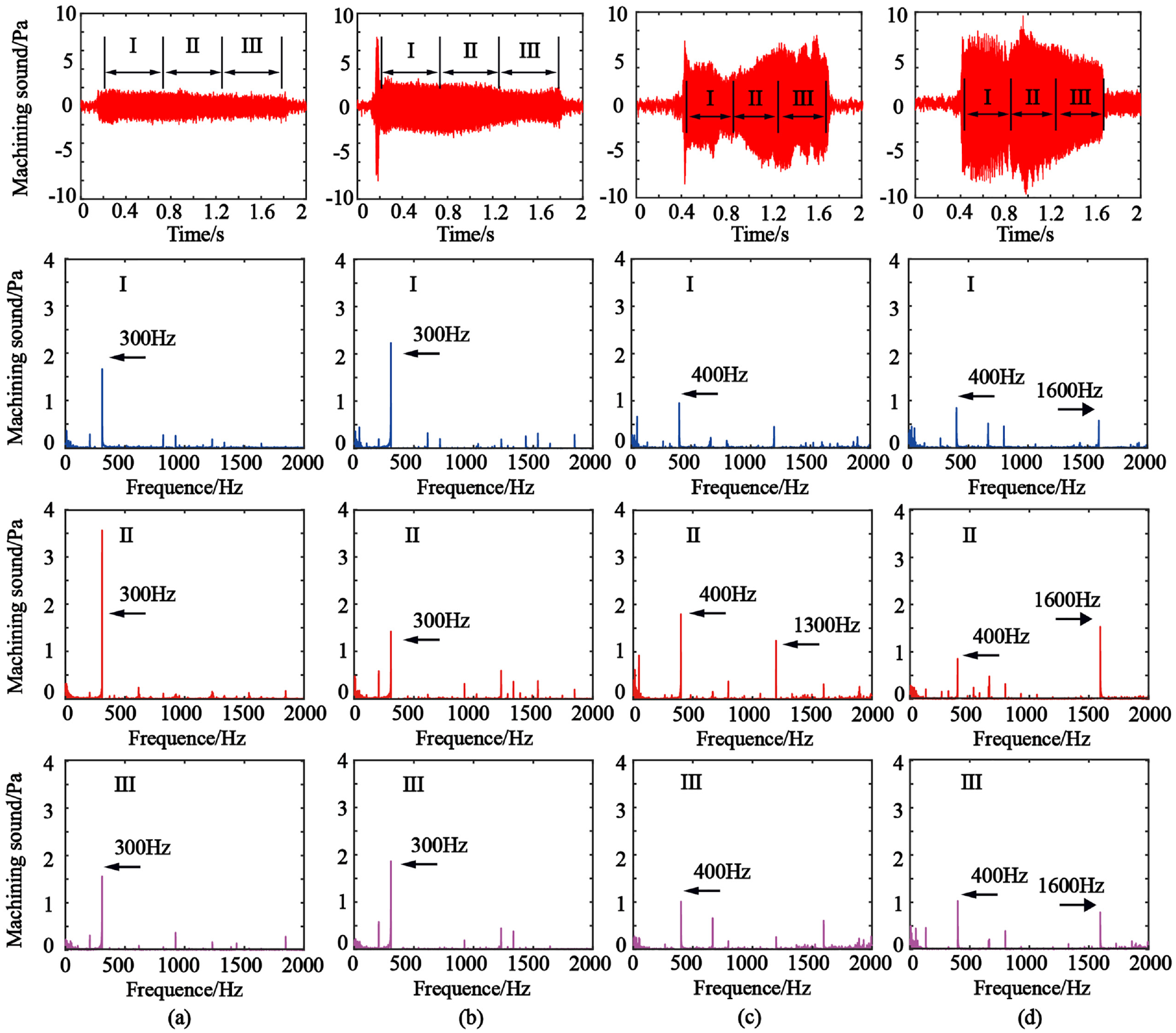
The machining sound in time and frequency domain: (a) n = 6000 rpm, ap = 3 mm, (b) n = 6000 rpm, ap = 5 mm, (c) n = 8000 rpm, ap = 3 mm and (d) n = 8000 rpm, ap = 5 mm.
The time domain signals during tool path I, II and III (Figure 10(b)) are transformed to the frequency domain. For n = 6000 rpm, ap = 3 mm (Figure 11(a)) and ap = 5 mm (Figure 11(b)), the tooth passing frequency of 300 Hz is dominant, indicating a stable cutting process. When n = 8000 rpm and ap = 3 mm (Figure 11(c)), the tooth passing frequency of 400 Hz is dominant for Path I. However, the chatter frequency of 1300 Hz increases by 60% for Path II. It indicates that the cutting process turns to be unstable from Path I to Path II due to the stiffness decrease. The machining process of Path III is evolved to be stable due to the stiffness increase. For n = 8000 rpm and ap = 5 mm (Figure 11(d)), the chatter frequency of 1600 Hz and tooth passing frequency of 400 Hz are clear for entire tool path, and is treated as unstable by combining with the machining sound in the time domain.
Conclusion
The machining of thin-walled part with high quality and efficiency has been a challenge due to its low and position-dependent machinability. Chatter theory in the milling process of thin-walled part considering nonlinearities (i.e. cutting force, structural stiffness and process damping) is investigated, and stability lobes are solved in time domain with an improved computational efficiency. Cutting tests are carried out to verify the simulation. The paper is concluded as follows.
The nonlinearities are introduced to be able to predict real behaviours, and coefficients identification of nonlinear chatter model are presented. However, the introduction of high order polynomials to represent nonlinearities complicates the mathematical modelling and solution of chatter stability in time domain. By formulating the displacement as an expanded form via the perturbation method, the time-consuming solution of delay differential equations is avoided. It is demonstrated that the proposed method attains high accuracy of classic time-domain solution, while the computational efficiency is much improved.
The dynamic cutting force, vibration and stability lobes considering nonlinearities are solved in the time domain with coefficients updated at each iteration, enabling the simulation of entire tool path. The proposed method achieves approximated accuracy with the semi-discretization method, but with the sacrifice of efficiency compared to the analytical frequency domain method. Besides, the adoption of specific criterion to determine an unstable process could cause deviation on the accuracy.
After formulating the displacement as an expanded form, numerical terms of the expansion with minor magnitude are neglected during the simulation of milling process, and the effect on the accuracy needs further investigation. Besides, only the dynamics of thin-walled part are considered due to its flexibility compared to the machine tool/cutter assembly. The proposed model can be extended to incorporate the dynamics of machine tool/cutter/workpiece for future work.
Footnotes
Appendix 1
μ
11,
Appendix 2
By writing the damping ratio ζx and ζy as εηx and εηy, equation (1) is formulated as equations (23)-(25) according to the order of ε.
Appendix 3
According to the Taylor series, the coefficients of ε1 are expanded as
Then, a0, b0, A0, B0 are obtained by solving equation (27).
Appendix 4
The integral part in equation (15) is solved as equation (28).
The feed rates are selected as c0, c1, c2, ……, cl, and the least square method is utilized to solve the cutting force coefficients.
where
The coefficients vector
where
The coefficients vector
Declaration of conflicting interests
The author(s) declared no potential conflicts of interest with respect to the research, authorship, and/or publication of this article.
Funding
The author(s) disclosed receipt of the following financial support for the research, authorship, and/or publication of this article: This work is supported by the National Natural Science Foundation of China (grant no. 51675032 and 91960108) and Fundamental Research Funds for the Central Universities (grant no. YWF-19-BJ-J-72).