
Abstract
Fabrication of complex and flat shapes is usually processed by milling operation with multi-point cutting tools. In this research, the potential of cryogenic and dry milling was investigated under varying cutting speed (50–250 m/min) and the feed (0.05–0.15 mm/tooth), while machining of AISI 52100 steel at a constant depth of cut. PVD TiAlN coated carbide cutting tool was employed in this research. The results show a reduction of 52%–78% in the white layer (WL) thickness under cryogenic cooling (LN2) environment due to its high thermal cooling effect. A drop out of 49% in the cutting temperature has also been observed if LN2 cooling is used instead of dry milling. Cryogenic cooling provides a 28%, 28%, and 29% decrease in the cutting forces; FX, FY, and FZ, in comparison with the dry milling. Furthermore, the roughness of the machined specimen reduces by 29% if the LN2 cooling mechanism is engaged in milling of AISI 52100. Study of chips morphology revealed that the cryogenic LN2 machining produced discontinuous, thin and small serrated chips with silver color.
Introduction
The process of separating the material from the workpiece using a rotating tool that consists of many cutting edges placed perpendicularly on the spindle is known as end milling. During the cutting process, most of the energy is consumed by the friction on the tool-chip junction, which is transformed into heat, leading to an elevated temperature in the cutting area.1–3 Additionally, the primary shear zone’s plastic deformation and the friction on the cutting face play a significant effect in the evolution of the material microstructure.
A white layer (WL) develops on the machined specimen of AISI 52100 steels, leading to microstructural changes. The white layer has a high hardness value up to 1000 HV which makes it difficult to engrave on the surface layer.4–8 It causes some unconstructive effects on the surface finishing of the products, such as surface fracture and malfunction consequences. There are mainly two mechanisms that facilitate the formation of white layers, that is, quick heating and quenching. 9 In ferrous alloys, microstructural changes occur due to the high temperature caused by machining. Ramesh et al. 10 reported that the white layer formation at high cutting speeds was mainly due to thermally-driven phase transformation. Barry and Byrne 11 and Chou and Evans 12 confirmed that there was an appearance of reverse martensite change and massive austenite concentration on the surface of the WL. The transformation of the machined plane to the austenitic state is carried out by the quick increase in temperature and pressure. The machined surface cools down rapidly as the tool departs and the critical speed of martensite formation is reached by conduction of heat into the work material. A surface cooling rate up to 104°C/s in hard turning may be achieved according to Chou and Evans. 12 As a result, the austenite structure in the machined layer is rapidly quenched and a structural transformation may occur. The white layer area is usually considered as the untempered martensite. Similarly, some austenite does not have sufficient time to convert. So the austenite remnants can still be detected on the surface.
Cryogenic machining has drawn increased attention these days as it has advantages including (1) improving the processing speed, (2) reducing the tool wear, (3) reducing the formation of white layer, (4) a decrease in the burr formation, (5) decreasing metal working temperature.13–15 Ravi and Pradeep Kumar 16 reported a temperature decrease in the cutting zone ranging from 43% to 48% due to the usage of liquid nitrogen coolant. Yildiz and Nalbant 17 examined that using LN2 cooling in machining enables considerable improvement in the manufacturing accuracy, surface morphology, and tool life. Ravi and Kumar 18 found the LN2 machining leading to considerable improvement in surface integrity in relation to the dry and wet milling. Umbrello et al. 19 reported that the adoption of LN2 led to better surface integrity with minimal WL development in the milling of hardened AISI 52100 steel.
The use of low-temperature fluids such as LN2 has a significant effect in improving the surface quality and the hardness of the machined surface and also the LN2 is safe, non-toxic, clean, and non-inflammable. Similarly, some research has confirmed that the adoption of the LN2 cooling approach on the flank faces and tool rake will have an effective improvement in grain refinement due to the applied cooling effect which results in the enhancement of machined surface hardness. 13 Paul et al. 14 assessed the tool life and surface superiority in the cutting of AISI-1060 steel material by applying the LN2 cooling environment. The result shows enhanced surface quality with the extended tool life. Ding and Hong 15 proved that the LN2 condition restricts the cutter damage and provides a sustainable tool life while cutting of Ti-6Al-4V alloy. Hong et al. 20 concluded that the use of LN2 cooling condition shows five times longer tool life when compared with the conventional cooling while cutting Ti-6Al-4V alloy.
Although many researchers had attempted to reduce the formation of WL in turning and grinding operations, few researchers have attempted in high-speed end milling to decline the thickness of the WL and improve surface topographies, especially in cryogenic milling. This research helps to reveal the impact of WL formation on the surface integrity of the machined parts and also the influence of dry and cryogenic milling on the WL formation, chip morphology, surface roughness (Ra), cutting temperature, micro-hardness, and cutting temperature for AISI 52100 steel were investigated. In this research, LN2 was supplied to the chip-tool junction during the milling process using a cryogenic cooling system. Various feed-speed combinations with the constant depth of cut were used in this analysis to investigate their effects on the end milling of AISI 52100 steel under dry and liquid nitrogen conditions.
Experimental
The milling operations were accomplished under a constant depth of cut using a carbide cutting tool on AISI 52100 steel for various speeds and feed. Dry milling and cryogenic milling are the cutting environment adopted in this research. In this work, the chip morphology, micro hardness, surface roughness, white layer thickness, cutting force, and cutting temperature are considered and compared with the dry and cryogenic milling processes.
Material
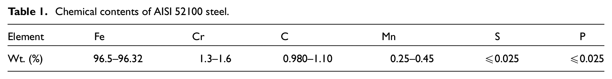
The material selected for this research is AISI 52100, with a 10 mm thickness, 100 mm width, and 175 mm length. It is a high carbon, chromium containing low alloy steel. The main application is bearings in rotator machines. Table 1 shows the chemical contents of AISI 52100 steel.
Chemical contents of AISI 52100 steel.
Cutting tool and force measurement
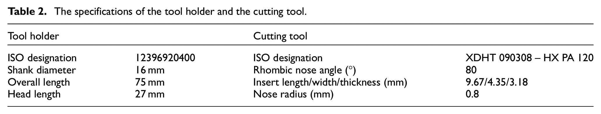
The tool holder for the end milling process was a WIDIA M680 shoulder end mill. The specification of the tool holder is given in Table 2. The type of insert used in this experiment is PVD TiAlN coated tungsten carbide cutting tool insert (XDHT 090308 – HX PA120), the specification is shown in Table 2.
The specifications of the tool holder and the cutting tool.
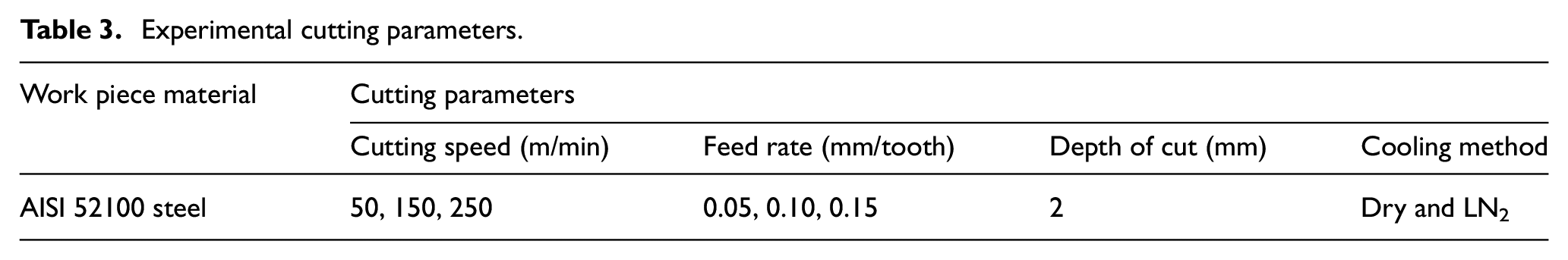
In this work, ARIX VMC 100 CNC milling machine was used to perform the end milling experiments. A three-component piezo-electric Kistler type (9257B) dynamometer was employed to measure cutting forces under each cutting condition. 18 The investigations were carried out in the dry and cryogenic milling conditions by varying the feed-speed combo. Table 3 shows the cutting parameters employed in the milling of the AISI 52100 steel. The cutting parameters used in this study were suggested by industry experts and previous studies. The axial and radial depth of cut was kept constant at 2 and 16 mm, respectively. 5
Experimental cutting parameters.
Cryogenic cooling system
In this research, the LN2 was adopted as a coolant for cryogenic machining, while the dry machining was carried out in atmospheric temperature without the use of coolant. Coolant supports the heat dissipation within the chip-tool interface. The cooling of the cutting process was performed by spraying the LN2 cryogen in the chip-tool interface. The schematic illustration of the experimental system is displayed in Figure 1. The cryogenic cooling system consists of a set of components including a nozzle, drier, compressor, pressure relief valve, liquid nitrogen container, pressure regulator, and braided stainless steel hose. The LN2 was stored in a 51.5 L cryogenic container (IBP-TA55). An external compressor was adopted to supply the compressed air into the cooling system with a delivery pressure of 3 bar. In addition, a pressure regulator was used to regulate the stability of the compressed air, which helped to spray the coolant on the specific region of the tool-chip interface. Drain filters were used to dry the compressed air. The compressed air passed through the inlet pipe of the cryogenic container and forced the fluid downwards. It led to the rise of the LN2 through the outlet pipe and finally, the LN2 was sprayed in the chip-tool interface through the nozzle (2 mm diameter) as indicated in Figure 2.
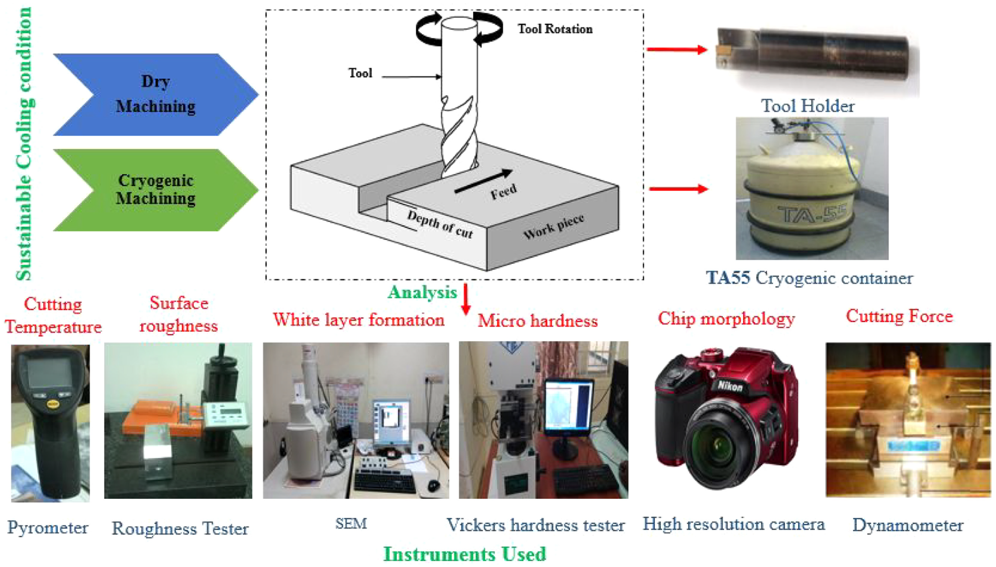
Schematic illustration of the experimental set-up.
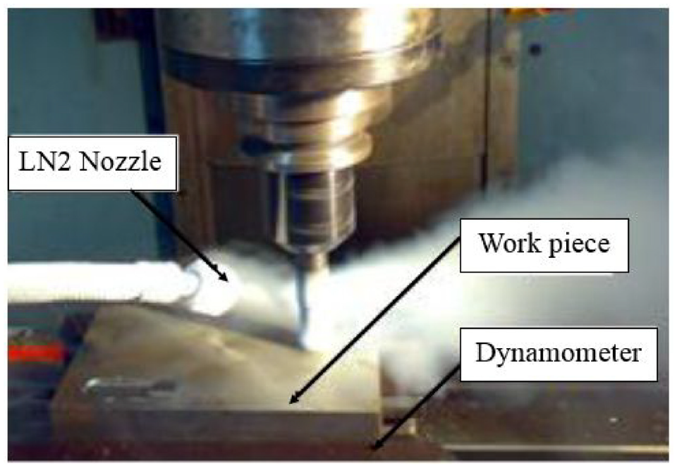
LN2 delivery nozzle at the cutting zone.
Calibrated infrared pyrometer with an accuracy of ±1.0°C was used to monitor the temperature (−50°C to +1000°C) on the chip-tool interface during dry and cryogenic milling. The maximum temperature was recorded by the infrared pyrometer with the help of infrared rays which were intruded on the chip-tool interface.
Surface characterization
The surface roughness of the cut was measured using a Taylor-Hobson Surtronic 3+ surface roughness tester with a 0.8 mm sampling length. After the milling operation, inclined, vertical, and horizontal surfaces can be measured in handheld positions. The Ra value was calculated by averaging three Ra values from three distinct locations.
In the micro hardness test, the load of 1 kg was applied on the Vickers (DPH) diamond indenter at a dwell time of 10 s which penetrates the cut surface on the specimens. 21 Three trials have been undertaken, from which the average value was considered for the analysis. The diagonal indentation effect was precisely measured using a microscope, and then the Vickers hardness was determined from the indent size and the load.
The thickness and occurrence of WL at the cut surface were examined using Scanning Electron Microscopy (SEM, S-3400N). Six specimens were analyzed using SEM. Three specimens from dry milling and three specimens from cryogenic milling at varying cutting speeds (Vc) of 50–250 m/min and at a feed rate (f) 0.15 mm/tooth were investigated.
Results and discussions
The outcomes from the investigation of dry and cryogenic machining circumstances on the Ra, cutting temperature, cutting force, micro hardness, WL thickness, and chip morphology were presented and discussed.
Cutting temperature
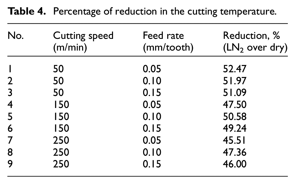
From the cutting temperature analysis, consequences in the implementation of dry and LN2 cooling environments were examined during milling of AISI 52100 steel. Figure 3 depicts the results of the cutting temperature. Table 4 shows the reduction in cutting temperature for various speed-feed combinations for cryogenic and dry machining. It was noted that the rise in the Vc and f led to an elevated temperature, which was eventually caused by the friction at the tool-work piece interface. Due to the increased Vc, less time was required for the material removal. Hence, there will be less contact at the tool-work piece interface. The cooling effect produced by the LN2 condition decreased the higher cutting temperature. The boiling of the liquid coolants resulted in the reduction of convection heat-transfer coefficient. 22 It was evident that with the increase in f, there will be an increase in the chip thickness which consecutively increases the friction and due to that increased friction there will be an elevated temperature. It was noted that the increase in the f led to the occurrence of a high rate of plastic deformation, which eventually led to the rise in the material removal rate and increased the temperature. At higher Vc, the increase in the friction at the chip-tool interface was due to the surge in the contact area, which reduced the LN2 cooling effect and considerably increased the temperature. 18 An average of about 49% decline in the cutting temperature was achieved using the LN2 cooling condition when compared with the dry milling.
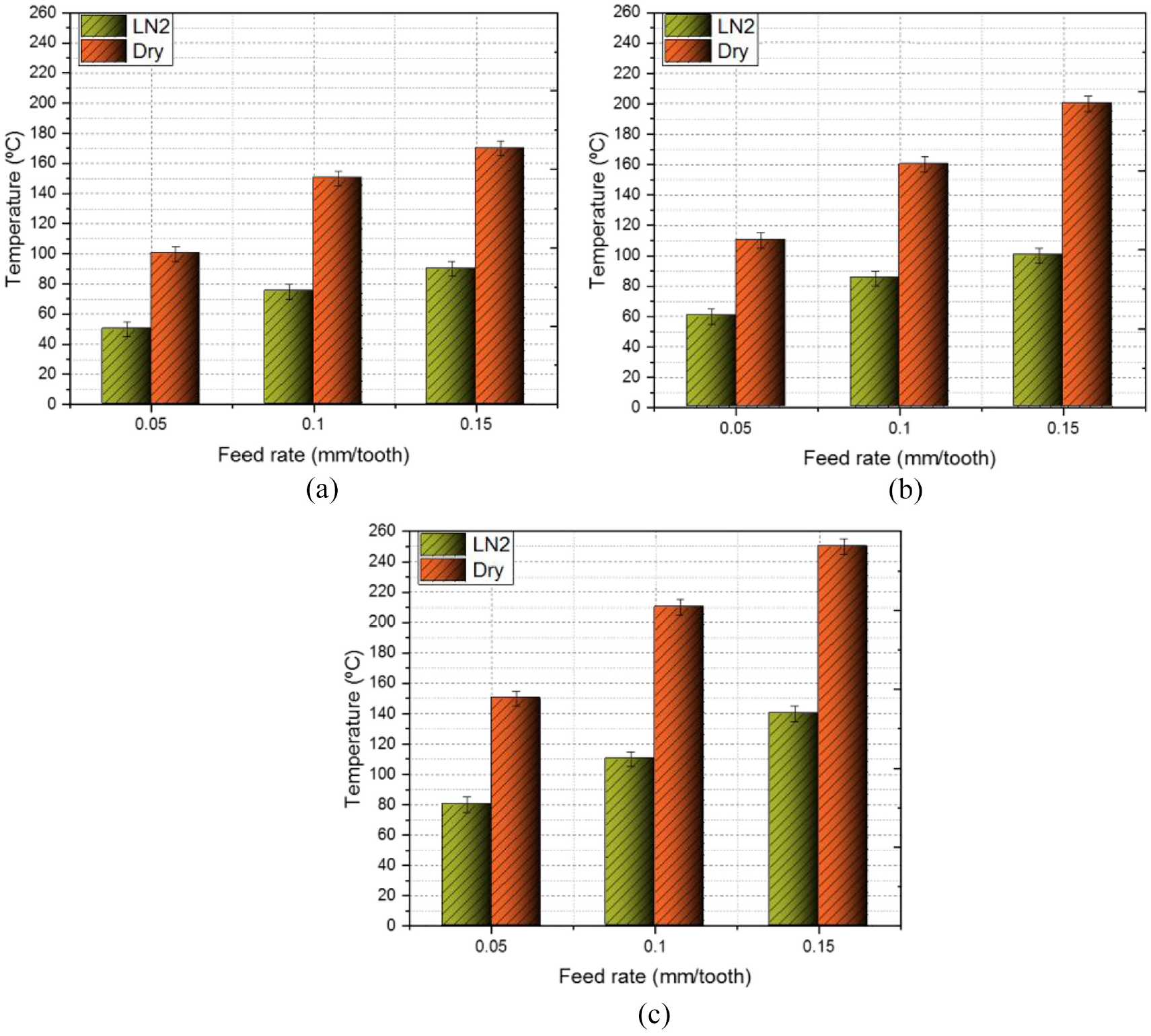
Cutting temperature variation at different Vc’s: (a) 50 m/min, (b) 150 m/min, and (c) 250 m/min.
Percentage of reduction in the cutting temperature.
Cutting forces
The fracture toughness and the yield stress were the major factors that influence the cutting force during the cutting process.20,23 Under various feed-speed combinations, the comparison of the FX, FY, and FZ, that is, the feed force, normal force, and axial force, were evaluated based on the two different machining conditions, which is shown in Figure 4. The lubrication and the cooling effect produced by the liquid nitrogen on the chip-tool interface helps to maintain the hardness and stiffness of the cutter material. It was also evident that the supplied high pressure LN2 coolant on the chip-tool interface lowered the chip’s stickiness near the cutting insert’s edges, from which the shear takes place with less cutting force in the work piece. 18 It was observed that the rise in the Vc considerably increases the cutting temperature and also led to the softening of the work piece. Hence, there will be a decrease in the cutting force. It was also evident that the softening decreases the yield stress of the work piece.
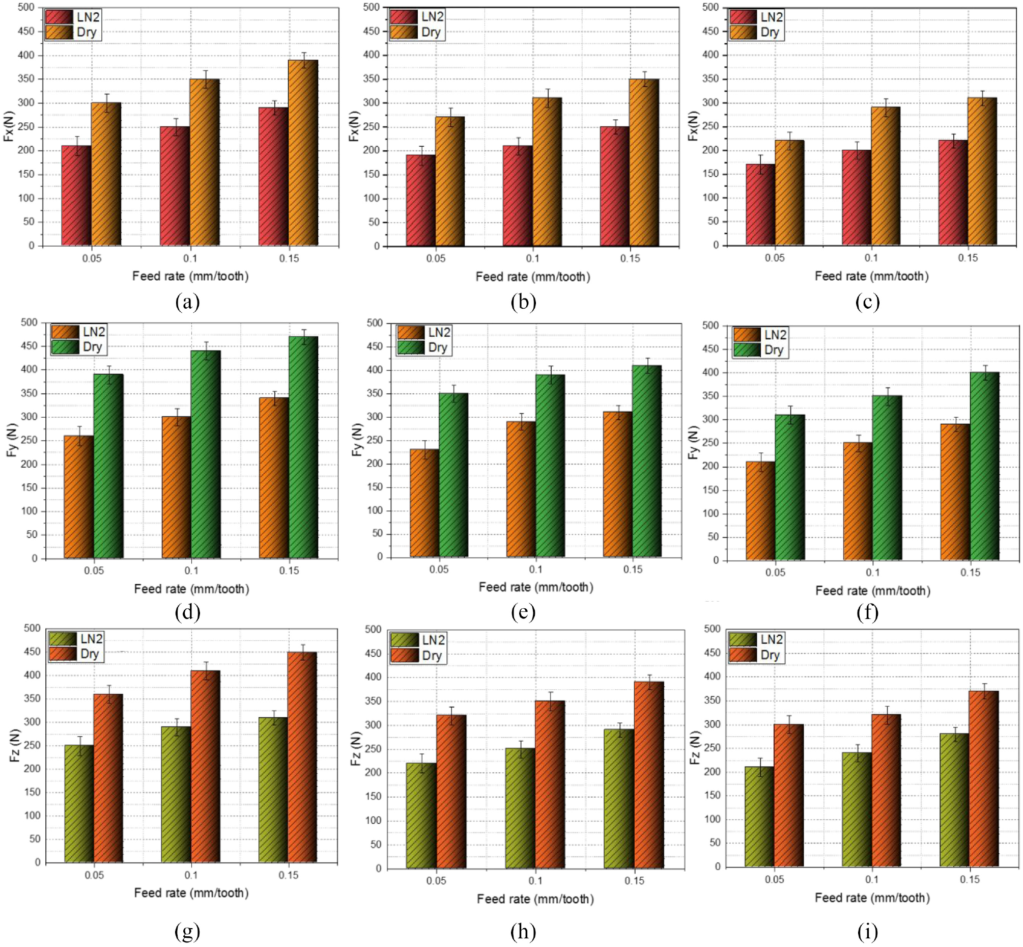
Comparison of the feed, normal, and axial forces at different Vc’s: (a, d, and g) 50 m/min, (b, e, and h) 150 m/min, and (c, f, and i) 250 m/min.
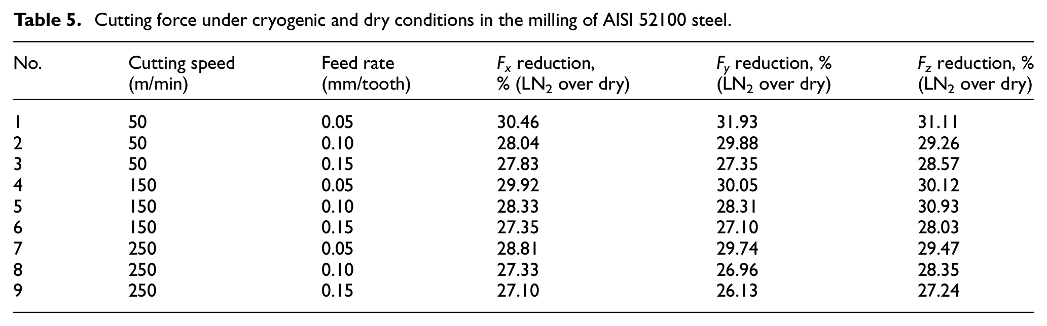
The percentage decrease in cutting forces observed on the LN2 machining condition in comparison with the dry milling is shown in Table 5. The mean decline in the cutting force (FX, FY, FZ) owing to cryogenic cooling was 28.35%, 28.60%, and 29.23%, respectively, over the dry machining. It shows that the LN2 cooling decreased the cutting load effectively because of an improved lube effect among the tool, chip, and the work material contact, which yielded lower friction.
Cutting force under cryogenic and dry conditions in the milling of AISI 52100 steel.
Surface roughness
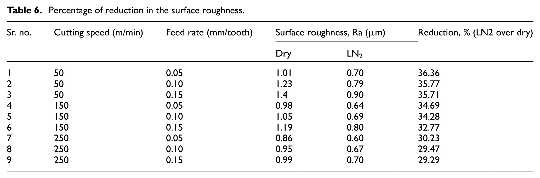
Under disparate machining conditions, the deviation in the Ra with respect to different feed-speed combinations during the milling is shown in Figure 5. It was noted that the rise in the f led to an increase in the Ra, which was due to the higher cutting force. Similarly, due to the tool wear, the elevated cutting temperature was observed in the chip-tool and tool–work material interface, resulting in the poor surface quality of the workpiece. The percentage decrease in Ra due to LN2 cooling is shown in Table 6. It is found that when the LN2 was applied onto the chip–tool interfaces, the Ra value of the work piece surface decreases. The cryogenic coolant’s cooling property allows the chips to slide more freely across the tool surface and reduce friction amid tool-chip contact. It was also evident that the cutting area temperature and tool wear was considerably reduced by the cryogenic cooling. From the investigation, the implementation of the cryogenic cooling environment reduced the Ra by 29%−37% and it was also noticed that the Ra was directly proportional to the f.
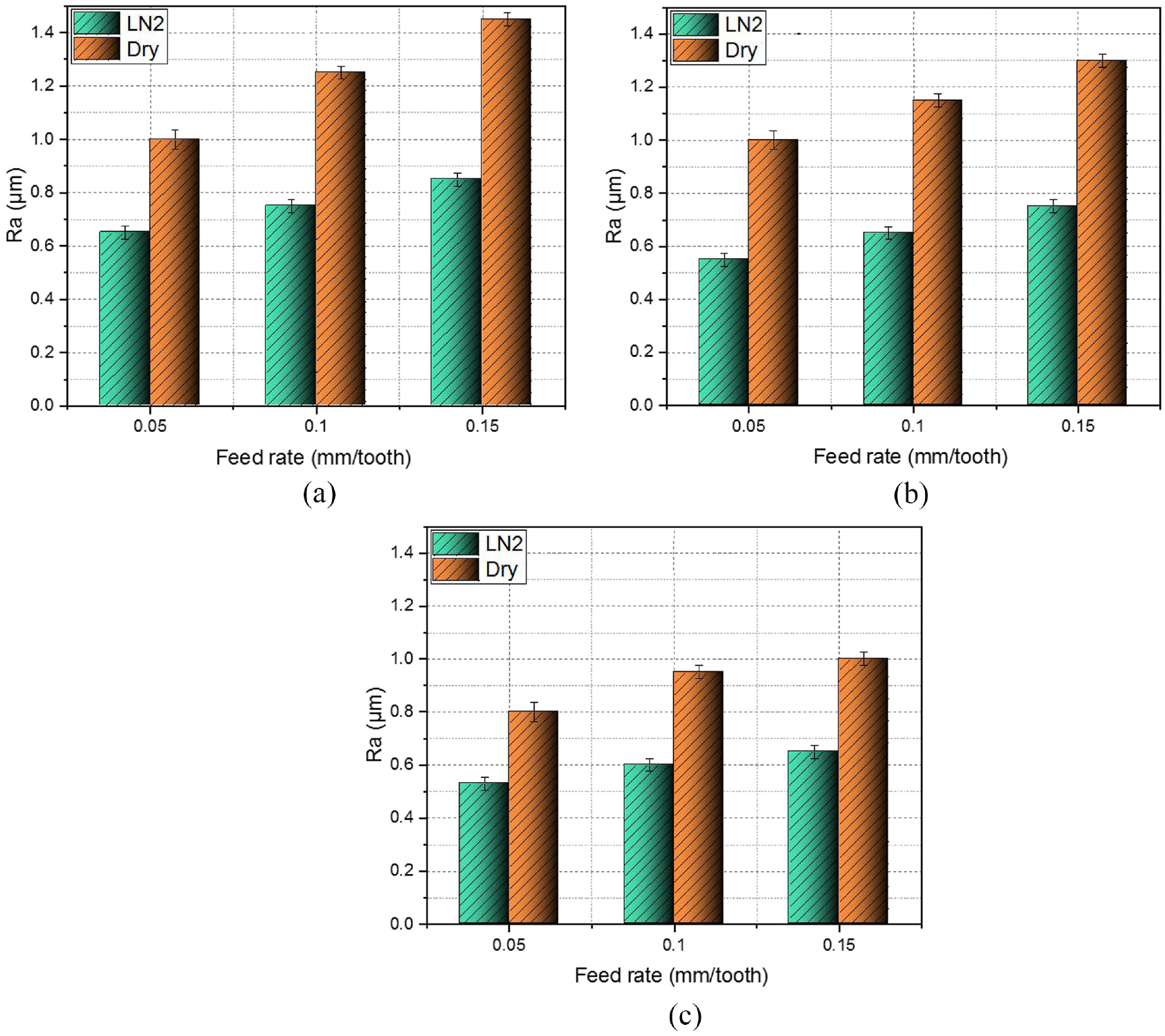
Surface roughness at different Vc’s: (a) 50 m/min, (b) 150 m/min, and (c) 250 m/min.
Percentage of reduction in the surface roughness.
White layer
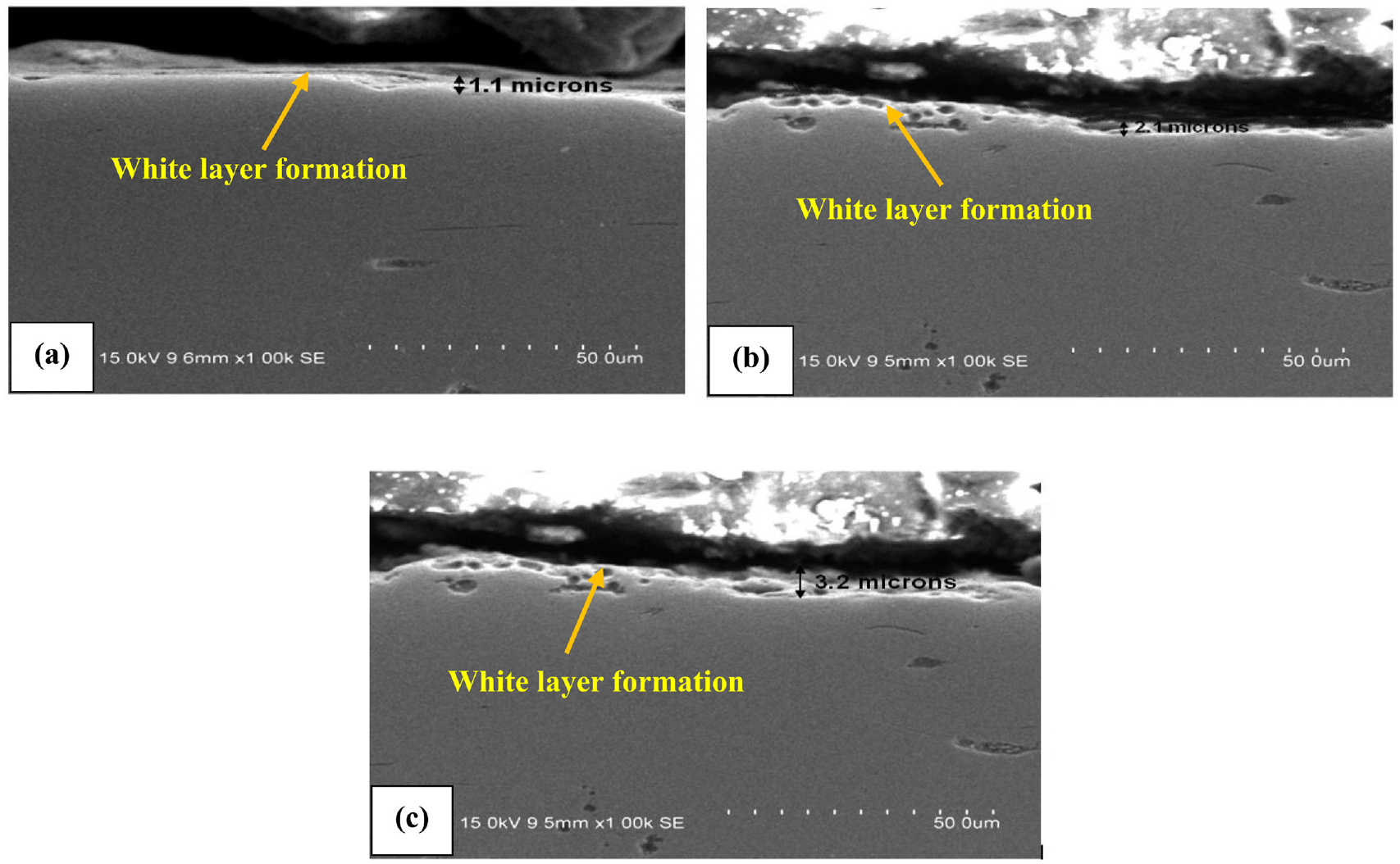
The development of WL has negative effects on the cut surface, which tends to embrittle the surface and induce micro cracks underneath the surface.4–7 The WL thickness of the machined samples was measured using optical microscopy. 7 Several micro cracks were observed in the dry milling condition, which was due to the intense heat created by the high Vc. 24 The micro cracks ran across the whole depth of the WL, mostly perpendicular to the sample’s surface. 6 Based on the comparison of Figures 6 and 7, it was confirmed that cryogenic cooling has a noteworthy effect on improving surface integrity. The rise in the f surges the intense heat generation in the cutting zone, which aims to the development of the WL, while the cryogenic machining supports to decrease the generated heat, minimizing the white layer thickness. Under dry machining, the white layer was detected on the cut surface and micro cracks were presented on the subsurface of the work piece, as displayed in Figure 6. The WL formation was confirmed under the OM and the SEM analysis. Its formation was due to the various machining conditions and the affected layer does not have WL over the surface. 6 It was evident that the development of the WL thickness was due to the rise in the Vc. Fewer cracks were formed on the cut surface at lower speeds and more cracks were formed at higher speeds. Experimental investigation reveals that the cryogenic coolant has considerable effects on the residual stress and the formation of the WL. WL was mostly considered as thermal damage or burnt, in which the thermal damage was reduced by the application of the cryogenic coolant. As a result, cryogenic machining lowers the temperature in the machining zone and lowers the WL thickness. 25 Comparing the cut surface under both conditions (dry and LN2 machining), it is found that the LN2 machining was associated with fewer cracks or sometimes no cracks. This is because of the decrease in the cutting zone temperature due to cryogenic coolant and thus constrains the phase transition. 26 A phase transition occurs because of the change in the temperature. 27 The change in the temperature was due to the increase in the Vc which leads to the micro cracks and it was evident in the SEM images. The WL thickness was reduced during the cryogenic cooling compared to the dry condition which is shown in Figure 7. The performances such as the fatigue life and cost for removal of the WL were the key criteria to reduce the WL formation, and also the surface integrity was considerably improved by the cryogenic cooling conditions.
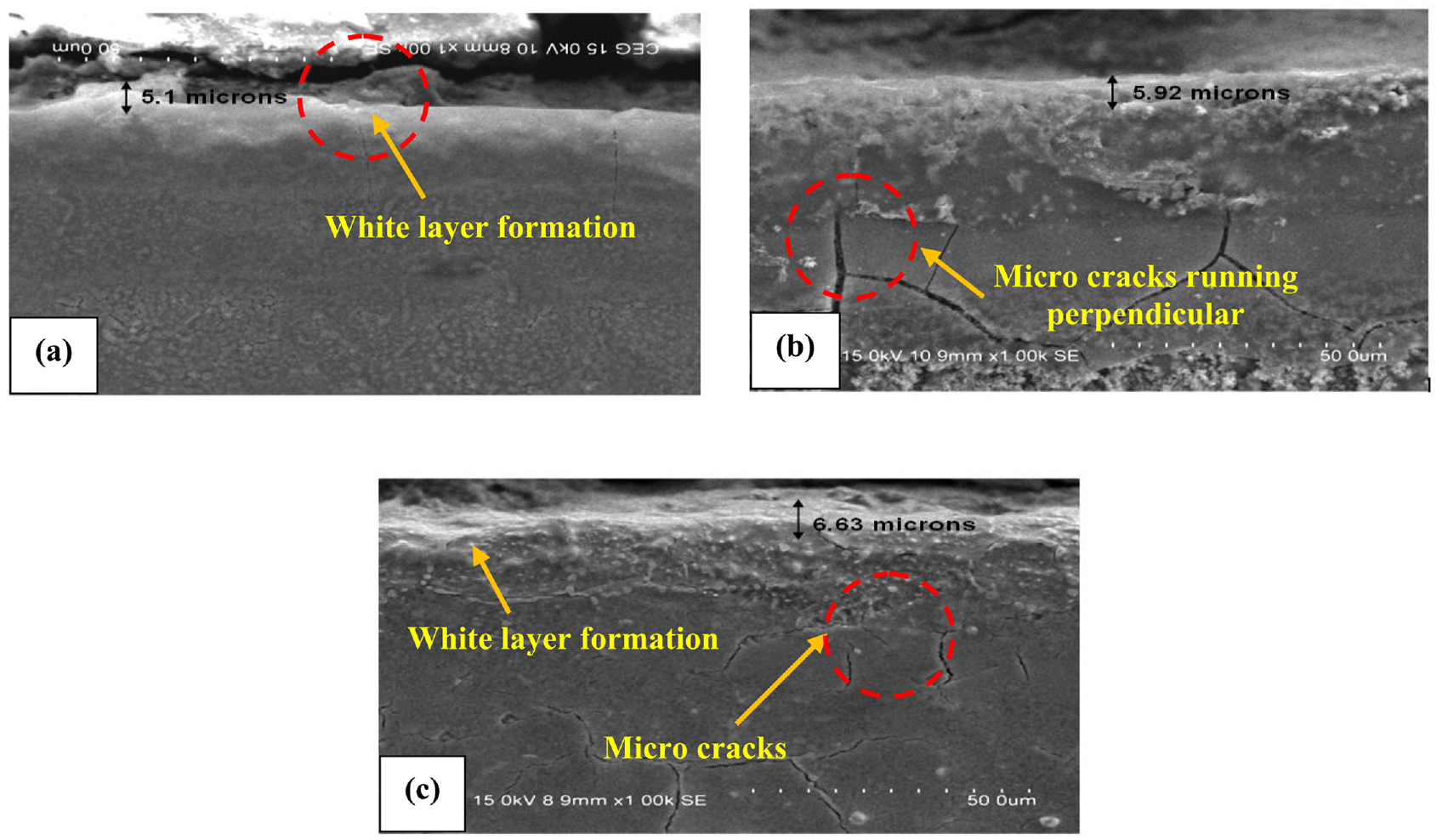
SEM images of specimens under dry milling at: (a) 50 m/min, (b) 150 m/min, and (c) 250 m/min.
SEM images of specimens under cryogenic milling at: (a) 50 m/min, (b) 150 m/min, and (c) 250 m/min.
The WL thickness at varying speeds was plotted in Figure 8. Temperature is an important factor for the WL formation and also it highly depends upon the Vc. 7 It was noted that the WL formation rises with the rise in Vc during the dry machining, which was due to the generation of high heat in the cutting place. 19 It was also noticed that the WL thickness was 5.1 and 1.11 µm for dry and LN2 at the Vc of 50 m/min. Compared to the dry machining, the WL thickness was reduced by 78.23% by the cryogenic cooling. The reduction of the WL thickness in LN2 machining was 64.52% and 51.73% relative to the dry machining as the Vc’s varied from 150 to 250 m/min. Overall, the LN2 coolant reduces the temperature rise on the cut surface which results in a 52%–78% reduction in the WL thickness.
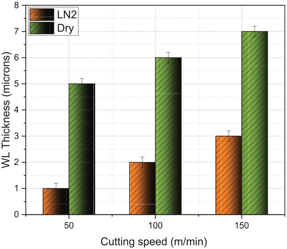
The white layer thicknesses with respect to Vc’s for the dry and cryogenic milling processes.
Micro hardness
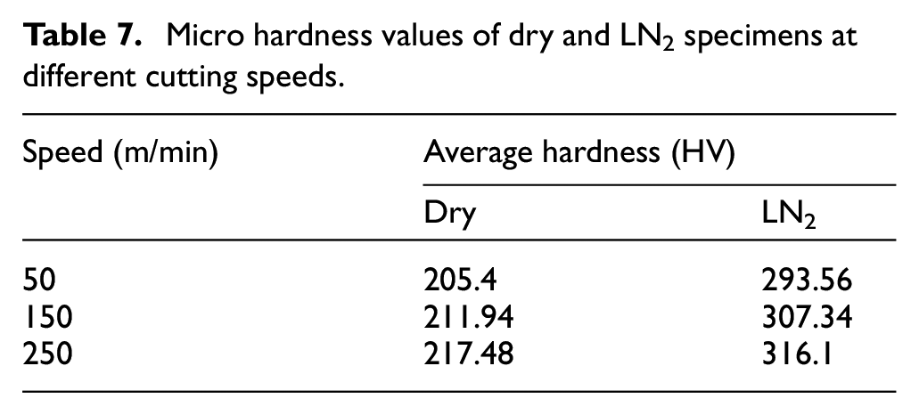
Vickers apparatus was used to measure the micro hardness and the results are tabulated in Table 7. There was an increase of 29%–32% micro hardness for the LN2 machining surface than that for the dry machining surface. The reasons for the increase in the micro hardness in the LN2 machining are 28 : (1) the thermal softening were decreased by the reduction of cutting temperature, (2) the presence of low temperature will lead to the occurrence of strain hardening of the machined parts, and (3) twinning deformation occurs in cryogenic machining in some cases due to the drop in the deformation temperature. The micro hardness value increases with increase in the Vc, which was due to the reduction in the thermal softening. 29 Hence, the cryogenic machining helps to increase the cooling effect, which in turns increases the hardness by strain hardening. 30 Similarly, the f was increased and led to a higher heat generation, which in turn caused thermal softening. Therefore, it will lead to a lower hardness. 4
Micro hardness values of dry and LN2 specimens at different cutting speeds.
Chip morphology
The images of chip forms in both situations (dry and cryogenic) are shown in Table 8, with the Vc’s of 50, 150, and 250 m/min and f of 0.05, 0.10, and 0.15 mm/tooth, at a 2 mm constant depth of cut.
Macroscopic features of the chips formed under dry and LN2 milling.
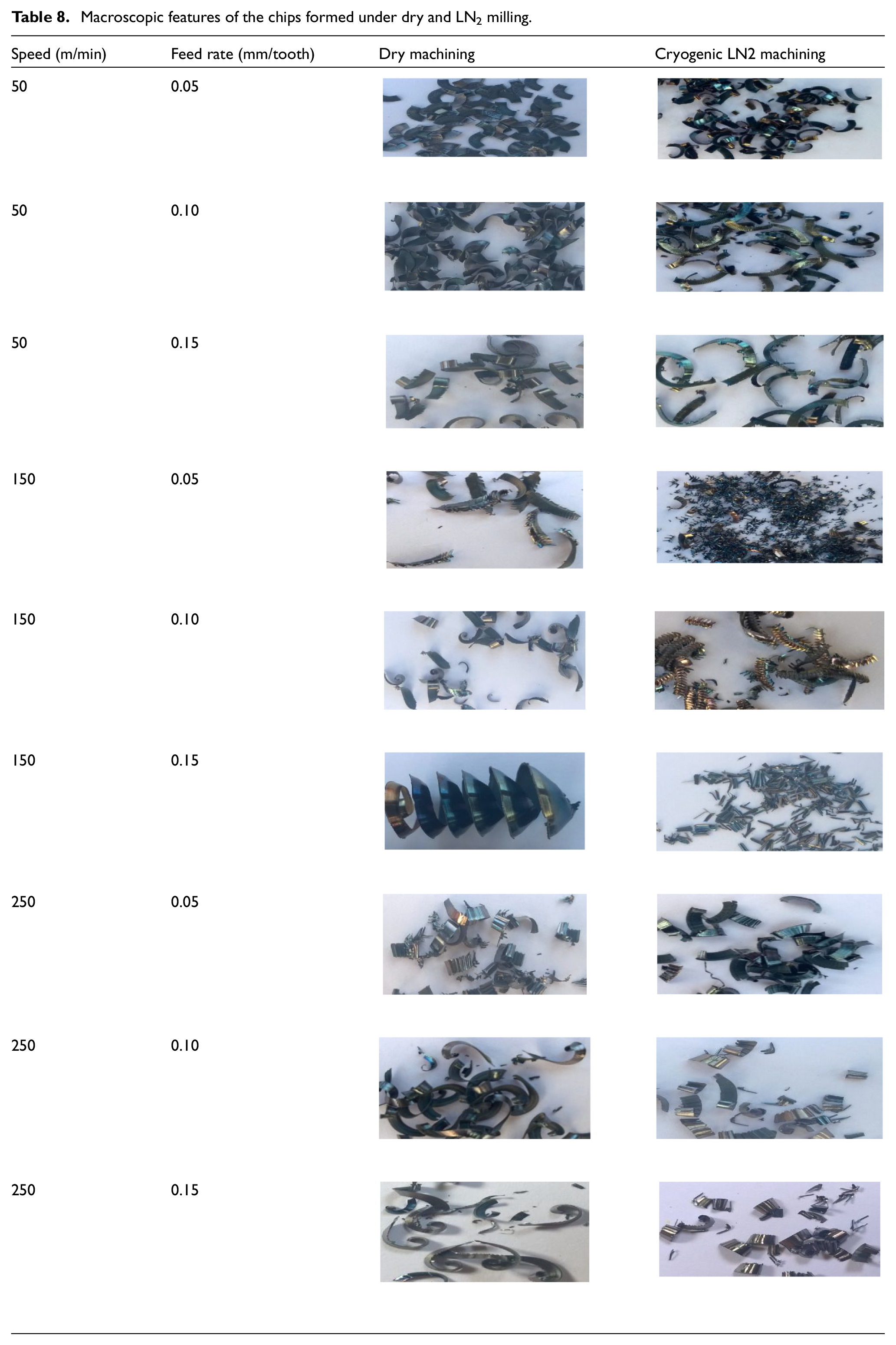
Long curled shapes of the chip were formed in dry milling and thin and small serrated chips were formed in the LN2 milling under the same machining parameters. It was also observed that under the two machining conditions, there was a difference in the colors of the chips. In dry cutting, the chips were in the color of dark blue, which was caused owing to the generation of the extreme heat in the tool-chip interface. But chips are in silver color under the cryogenic cooling condition, which indicates there was a lower heat generation between the tool and the chip surfaces. Severe shearing deformation has occurred in the dry machining as the chips were associated with large serrated teeth. 31 In contrast, in cryogenic machining, lower serrated teeth were observed due to the relatively lower shear forces. The development of nitrogen cushion at the chip-tool interface lubricated the cutting process and reduced the local friction during cryogenic machining.
From the chip morphology, it was observed that the rise in the Vc and f will eventually lead to an increase in the curl length of the chip. With a lower Vc, lower heat was generated. The brittleness plays a major role at the lower temperature zone and leads to smaller chip size in the cryogenic condition. During the high speed machining, more heat was generated and it led to longer chips for the dry environmental condition. Similarly, when the f was increased then there would be an occurrence of flank wear due to the increased thickness, which led to the development of extensive heat and an increase in the curl length of the chip. 18 In the cryogenic cooling environment, it was observed that the chips snarled into small pieces or a few turns, but in the dry machining condition, a thicker chip was formed and also it was difficult to break when compared with the cryogenic cooling conditions. The discontinuous thin chips were formed during the high Vc with cryogenic machining condition. But continuous thick chips were formed in the dry machining condition which in turn created an increased tool wear and poor surface finish. It was also observed that during the cryogenic machining, chips like small washer types with fine thickness were formed at higher feed-speed combinations.
The lack of cooling and lubrication between the tool-chip and tool-work material interface was the primary responsible factor for the increase in chip curl length. 32 When the adequate cooling and lubrication effect was provided onto the chip-tool and tool-work material interface, smaller chips can be obtained, this was due to the brittle nature of the material. 18 Ahmed et al. 28 investigated that chip brittleness was enhanced by the cryogenic cooling condition, which leads to easy chip breaking due to the interaction of the evaporated gas with the cutting tool edge.
The chips acquired under LN2 cooling were smaller than those obtained under dry machining, which is a favorable type of chip for machining. This was mainly due to the cooling effect on the chip-tool interface produced by the cryogenic condition which leads to the fall in the cutting temperature. 33 The absence of chip curl was mainly due to the increased hardness by the lower temperature in the chip-tool interface. Similarly, the drop in the ductility of the material enhances the chip brittleness and facilitates chip breaking.
Conclusion
In this work, cryogenic milling and dry milling were conducted on AISI 52100 steel at different cutting speed-feed combinations. The major conclusions drawn from this study are as follows:
■ The LN2 cooling system developed in this work can significantly reduce the cutting temperature for the end milling process when compared to dry milling. About 46%−52% reduction in cutting temperature at the chip-tool interface is observed in the LN2 cooling environment.
■ With respect to cutting forces (FX, FY, and FZ), the supremacy of the LN2 cooling system is witnessed in the milling of AISI 52100 steel. A notable decrease of 28% in cutting forces magnitude is revealed when the LN2 system is used instead of dry milling.
■ The cryogenic milling led to improved surface quality than the dry milling. The surface roughness achieved under LN2 mechanism is 29% lesser in contrast to that achieved with dry milling. When compared with dry milling, cryogenic milling shows a 29%–32% increase in the micro hardness of the machined surface.
■ In terms of WL thickness, approximately 52%–78% reduction of WL thickness is found in the LN2 cooling environment when compared with the dry milling. Moreover, micro cracks present under the cut surface are restricted by the implementation of LN2 system. Furthermore, the chips obtained under LN2 cooling are smaller than those under dry machining, which is a favorable type of chip for better machining.
The main limitation of this work is that the temperature gradient and microstructure evolution along the thickness of the white layer has not been characterized, which would be the main work in the future.
Footnotes
Acknowledgements
The authors thank Dr. Catalin Iulian Pruncu of University of Strathclyde and Dr. Fengzhen Sun of Imperial College London for proofreading assistance and entire guidance which makes possible drafting this work.
Author contributions
M Saravana Kumar: Methodology, writing-Original draft, Review and editing, Formal analysis, PK Shafeer: Conceptualization, Investigation, Data curation, Project administration, Investigation, Nimel Sworna Ross: writing-Review and editing, Kashif ishfaq: writing-Review and editing, Adeolu A Adediran: writing-Review and editing, Abayomi Adewale Akinwande: writing-Review and editing.
Declaration of conflicting interests
The author(s) declared no potential conflicts of interest with respect to the research, authorship, and/or publication of this article.
Funding
The author(s) received no financial support for the research, authorship, and/or publication of this article.
Ethical approval
This article does not contain any studies with human participants or animals performed by any of the authors.
Consent to participate
This article does not contain any studies with human participants performed by any of the authors.
Consent to publish
The authors provide their consent to publish this work in Proceedings of Institution of Mechanical Engineers, Part B.
Availability of data and materials
The raw/processed data required to reproduce these findings cannot be shared at this time as the data also forms part of an ongoing study.