
Abstract
The cutting force provides important information such as tool condition, chips information, and machining parameters selection. Thus, many researchers have proposed some methods for cutting force monitoring. However, most of them are only applied in the laboratory due to lower flexibility and complex installation. In this paper, a split multi-axis toolholder dynamometer is proposed and developed, which can equip different types of machining spindle and fit for multi-size tool. It consists of six capacitive sensors that can sense four deformations in vertical direction and two deformations in circumferential direction. Meanwhile, the distance between two plates in the vertical and circumferential capacitive sensors was adjusted separately. An acquisition and wireless transmission unit was designed to detect the capacitive variation and then transfer data to upper computer. Finally, a standard tool holder and a force sensing unit, a bottom socket, an acquisition and wireless transmission unit, a lithium battery, a cover were installed and debugged as a whole system. To validate its static and dynamic characteristics, various tests are conducted. The result demonstrates that the toolholder dynamometer can accurately and reliably monitor four-axis cutting force in the milling and drilling operations.
Keywords
Introduction
Intelligent manufacturing system demands that machining process must increase product quality, reduce manufacturing cost, and enhance higher processing efficiency. Moreover, monitoring technology can meet the above-mentioned requirements. Among all the monitored variables, the cutting force is the most important one, whose measurement can be used as predicting tool wear, 1 understanding the principle of chip formation, 2 tool geometry design, 3 monitoring tool condition, 4 predicting chatter, 5 and optimizing the machining parameters. 6 Therefore, it is essential to monitor the cutting force timely and accurately.
Currently, piezoelectric dynamometers fabricated by Kistler company are widely used in the laboratory due to its higher precision and reliability. Besides, Yaldız et al. 7 and Totis et al. 8 developed four-component dynamometers by using strain gages and triaxial piezoelectric dynamometer respectively. However, the workpieces must be installed on the dynamometer though the bolt connection, which limits their size and mass. In addition, due to their high cost and destructive installation, they can only be exploited in the lab but not in the workshop.
To satisfy higher flexibility and reconfigurability in the factory, the cutting force sensors should be integrated into a tool holder or spindle in the machining process. Andreas 9 used a capacitance displacement sensor integrated into the spindle for measuring static and dynamic variations of the gap between the sensor and the rotating spindle in order to indirectly monitor the cutting force. Byrne and O’Donnell 10 developed and integrated two piezo-electric force sensor rings into a driven motor spindle for measuring drilling force to achieve process monitoring. Martin 11 placed a force ring into the machining spindle to monitor fault diagnosis in the machining process. However, integrating into spindle cannot be widely previous device, which decreases its flexibility and reconfigurability.
To maximize the reconfigurability and flexibility, the way that the force sensors were mounted into the tool holder was proposed. They were approximately classified as strain-gage, piezoelectric, capacitive, and other type according to the sensing principle. Totis et al. 12 devised a toolholder dynamometer for monitoring force of single cutting edge, which integrated triaxial piezoelectric force sensor into each cutting edge. Several piezoelectric rotational dynamometers have been manufactured by Kistler company. 13 However, they are also not available for industrial applications due to their high cost and inconvenient installation. Ma et al. 14 integrated PVDF sensors into a cutting tool to measure radial force and torque. 15 Luo et al. 16 placed PVDF sensors into each tooth of the milling cutter to test three-axis force of per tooth. However, what they did was lack of low-frequency performance test and complex circuit caused toolholders huge volume.
Therefore, a group of researchers turned their eyes to strain gage due to its low cost, small size, and mass. Rizal et al.17,18 constructed and designed an integrated toolholder dynamometer with a cross beam adhered to 24 strain gages. Wu et al. 19 integrated eight strain gages into an annular groove that was located on the toolholder to perceive axial force and torque. Suprock and Nichols 20 developed a low-cost torque monitoring system by utilizing a strain-resistor sensor located on the cutting tool. Dini and Tognazzi 21 identified tool condition by using toolholder dynamometer whose core was a low-cost, small-size, and strain-type sensor. However, due to the sensing principle of strain gages, they are required to design complex structures to decouple multicomponent forces. Moreover, the sensitivity of ordinary foil strain gages is not high, and their designed structures often ignore the stiffness of the toolholder to improve the sensitive characteristics, which limits the dynamic characteristics of the toolholder.
Hence, several scholars have proposed another type of toolholder dynamometer. Xie et al.22,23 integrated four capacitive displacement sensors into a modified toolholder to measure four-component force due to its high sensitivity and wide measuring frequency. However, it was difficult to adjust the gas between a fixed plate and a movable plate because of the tiny micron level gap. Furthermore, modifying commercial toolholder BT50 has decreased its reconfigurability and flexibility. Liu et al. 24 developed a toolholder dynamometer based on fiber bragg grating, but the sensors was easily affected by the cutting environment such as cutting fluid, chips, etc.
In this paper, a split toolholder dynamometer based on capacitive sensors is presented to solve the problems of difficult adjustment of the gap between the pole plates and poor versatility of the toolholder. The toolholder dynamometer is composed of a replaceable standard tool holder, a force sensing unit, a bottom socket and a data acquisition and wireless transmission unit, which is capable of monitoring four-axis force not higher than 1000 N of force and 50 Nm of torque in milling and drilling process. The prominent advantage is that multi-type standard tool holder and multi-size tool can be assembled with the toolholder dynamometer.
Development of toolholder dynamometer
Design of split toolholder dynamometer
Although the cutting force acts on the milling cutter during the milling process, it is transmitted to a tool holder through a tool. Therefore, the tool holder acts as not only an element of clamping the tool, but also the bearing part of the cutting force. Therefore, the cutting force acting on the milling cutter can be simplified to the tool holder, which generates four-axis force, namely the axial force Fz, the radial force Fx and Fy, and the torque T. Hence, the present study focuses on developing an integrated toolholder dynamometer to monitor four-axis cutting force in the machining operations.
It is an important factor to consider the flexibility and reconfigurability for a toolholder dynamometer. Figure 1(a) illustrates a split-type tool holder which includes a standard tool holder, a force sensing unit and a bottom socket. The force sensing unit can connect multi-type standard tool holders and fit the bottom socket well that can clamp multi-size tool. In this work, a BT30-FMB22-40 (Bright-tools Co. Ltd.) toolholder is selected with the material of 40 Gr. A cross grooves along the force sensing unit’s radius direction are designed to form the horizontal deformable beams and vertical deformable beams that are mounted on the sensors, as illustrated in Figure 1(b). These structural dimensions of the force sensing unit are shown in Figure 1(c) which lays a foundation for the subsequent optimization.
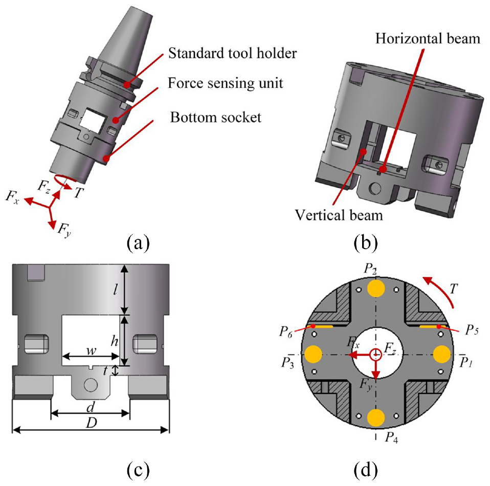
Design of toolholder dynamometer: (a) assembly relationship, (b) the force sensing unit, (c) structural dimensions of the force sensing unit, and (d) deformation detection positions.
In order to decouple multi-dimensional force, a total of six deformation detection positions are located on the horizontal beams and the vertical beams as shown in Figure 1(d). Four of them (P1–P4) are evenly placed on the horizontal deformation beams to detect four Z-direction deformations which are used to calculate three-component forces, namely axial force Fz and radial forces Fx and Fy. Meanwhile, two deformation detection positions (P5–P6) are set at the vertical beam, and the torque T is calculated by the circumferential deformation data of the two points. Due to the structural symmetry, under the action of a single axial force Fz, the P1–P4 have the same deformation in magnitude and direction. Besides, the vertical beam is only subjected to compression under Fz, so the circumferential deformation at positions P5 and P6 is almost zero. When the force sensing unit is only subjected to radial force, taking Fx as an example, the radial force at the milling cutter produces a bending moment effect at the force sensing unit. One side of the force sensing unit will be in a compressed state, and the other side will be under tension. At the same time, the two positions P1 and P3 along the direction of the force Fx will generate equal and opposite deformations, while the bending moment effect has a slight influence on the detection positions P2 and P4 whose deformation is small. In the same way, under the sole action of the torque T, the deformations of the vertical beam positions P5 and P6 will be equal in magnitude but opposite in direction.
Finite element analysis
Static analysis
To validate the correctness from above the structural design, the finite element analysis (FEA) was conducted. Based on the ANSYS Workbench platform, a three-dimensional model of the toolholder dynamometer was established and divided into meshes by using the Hex Dominant method. To improve the analysis accuracy and control the consumption of computing resources, only the meshes of the deformed beam part were refined as shown in Figure 2(a). In practical applications, the toolholder dynamometer is assembled on the spindle. Due to the sufficient spindle stiffness, the taper shank of the toolholder dynamometer is fully constrained as a fixed end. Considering the loading situation under actual working conditions, these forces including axial force Fz and radial force Fx (take Fx as an example) are loaded to 1000 N, and the torque T is applied to 50 Nm at the front end of the toolholder dynamometer. Finally, the deformation nephograms of each beam under each force are achieved as shown in Figure 2(b) to (d).
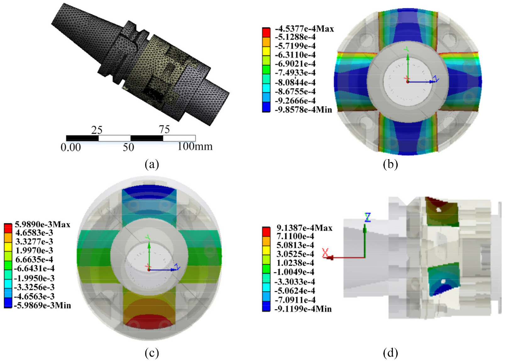
Spilt toolholder of static analysis: (a) mesh model, (b) deformation nephogram under Fz, (c) deformation nephogram under Fx, and (d) deformation nephogram under T.
It can be observed from Figure 2(b) that four horizontal beams have the same deformation in magnitude and direction under a single axial force Fz, and the largest deformation appears in the middle part of the horizontal beam. Figure 2(c) shows when the toolholder dynamometer is only subjected to radial force Fx, it will generate equal and opposite deformations along the direction of the force Fx, and the other two deformations are near to zero, which demonstrates one side of the toolholder dynamometer is in a compressed state, and the other side is under tension. Figure 2(d) shows under the sole action of the torque T, one of the vertical beams is positive and the other is negative, but their magnitudes are the same. All the simulation analysis results are consistent with the analysis of structural design.
Comparison of split and integral toolholder
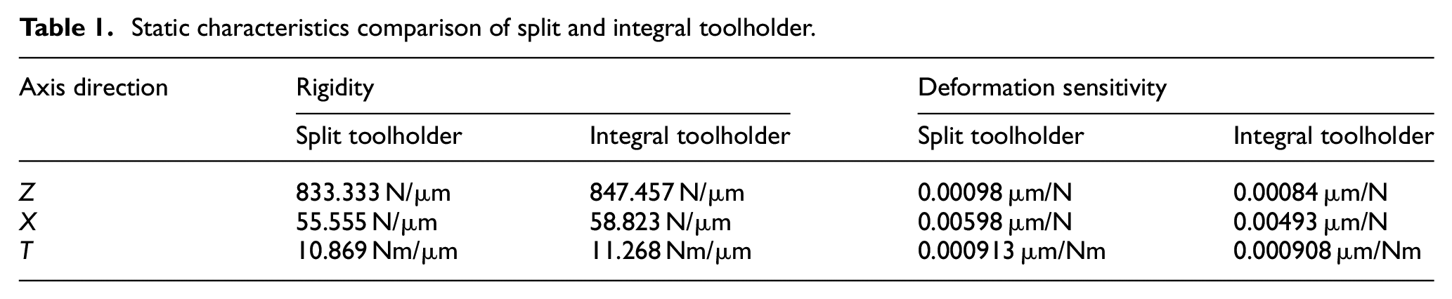
Xie et al. 22 proposed an integral toolholder based on a modified standard BT50 toolholder for monitor cutting forces. To compare its performance, the finite element analysis was carried out. First, a modified BT50 model was established and meshed in the ANSYS Workbench as shown in Figure 3(a), whose dimensions were the same as the split toolholder proposed in this article. According to the above analysis method, the deformation nephograms at the deformable positions were displayed in the Figure 3(b) to (d). It can be observed from Figure 3(b) to (d) that the maximum deformations of the integral toolholder under each component force are close to the above split toolholder. To further illustrate this result, the whole rigidity and deformation sensitivity at the deformable positions are respectively calculated as shown in Table 1. It can be seen from Table 1 that the rigidity and deformation sensitivity between them are very close. In addition, the rigidity of integral toolholder is slightly greater than that of the split tool holder. However, the deformable sensitivity of integrated tool holder is slightly smaller than that of the split tool holder. Therefore, compared with the integral toolholder, the split toolholder not only retains the stiffness and deformation sensitivity characteristics of the integral toolholder, but also can adapt to different types of spindles.
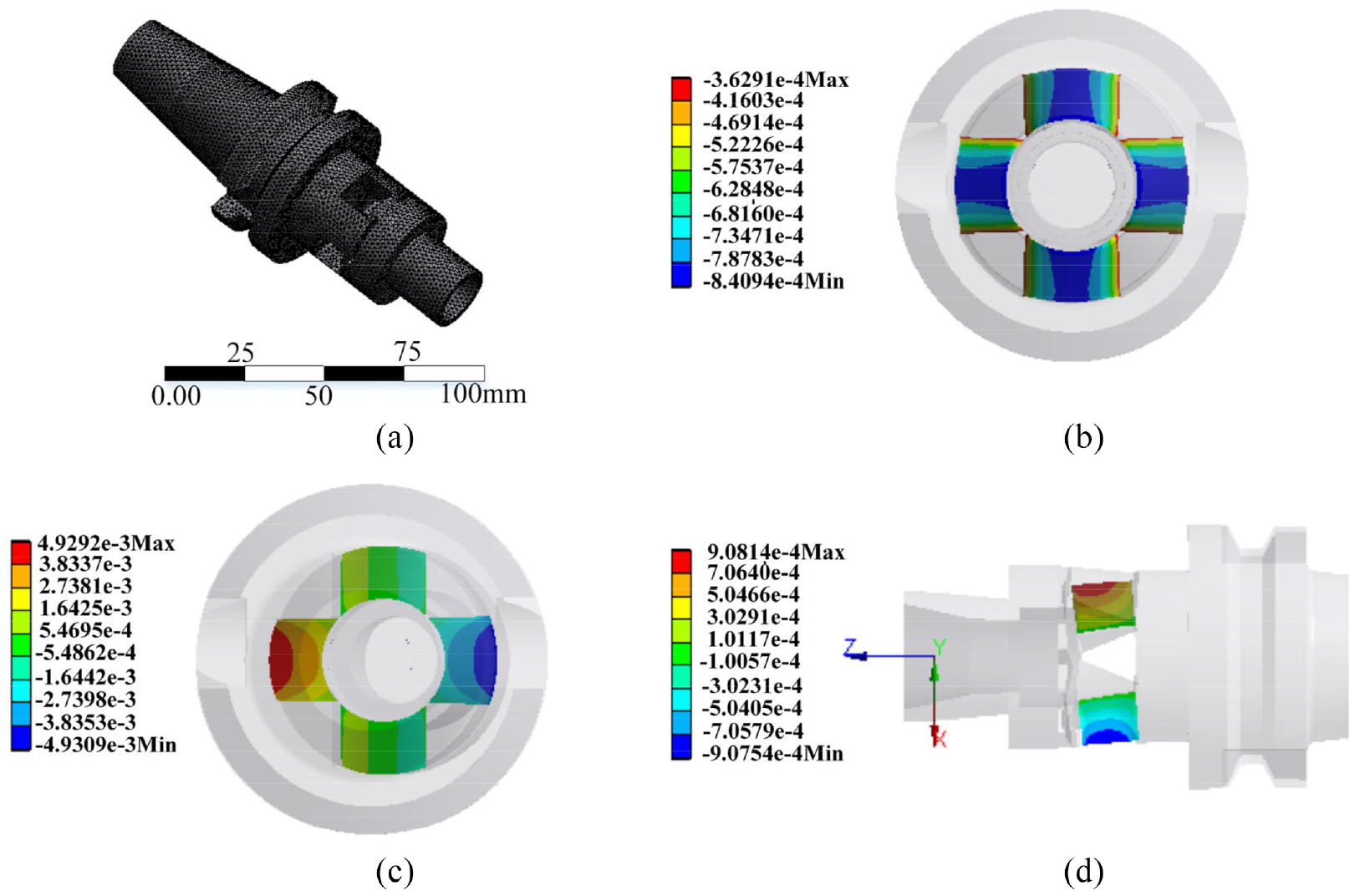
Static analysis of integral toolholder: (a) mesh model, (b) deformation nephogram under Fz, (c) deformation nephogram under Fx, and (d) deformation nephogram under T.
Static characteristics comparison of split and integral toolholder.
Optimization of structural parameters
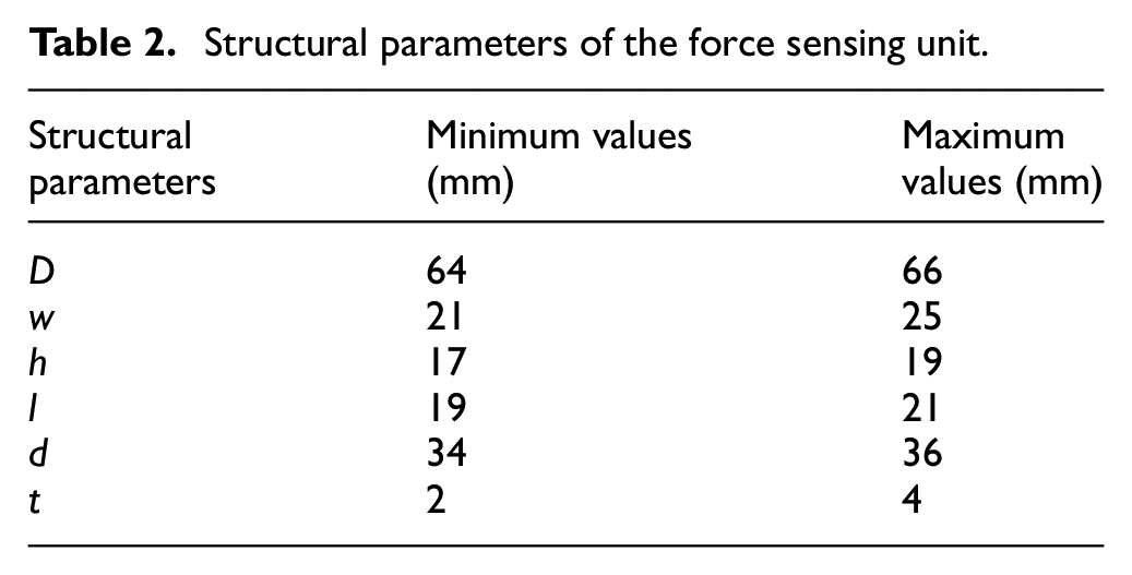
To enlarge the sensitivity of the toolholder dynamometer, the capacitive sensors are located on the deformable beams. However, it decreases the force sensing unit’s stiffness and further affects the whole stiffness of the toolholder dynamometer. To balance this contradiction, multi-objective optimization technology is discussed to determine the structural parameters of the force sensing unit whose minimum and maximum values as constraints are illustrated in Table 2. The optimization goal is to maximize the deformation in three directions, namely, Def_Z, Def_X, and Def_T. Moreover, the stiffness affects the first-order natural frequency (FNT) which will be used as another optimization objective, that is, maximize the FNT. Based on the static analysis, a direct optimization method has been utilized by ANSYS Workbench. The deformable sensitivities on all parameters are obtained by the optimization method, whose results are shown in Figure 4. Figure 4 illustrates that the structural parameters w, h, and t have a great influence on the deformation (Def_Z, Def_X, and Def_T) while the influence of D, l, and d can be neglected. In addition, the width w has a marked impact on the axial and torsional deformation, and the thickness t makes a significant impact on the radial deformation, and the length h dramatically affects all directions’ deformation. In addition, we solve the candidate point with the optimized module by the direct optimization method, and the results are rounded as follows: the parameters (h, w, and t) are finally determined as 19, 24, and 3 mm. other parameters (D, d, and l) are ensured as 65, 35, and 21 mm.
Structural parameters of the force sensing unit.
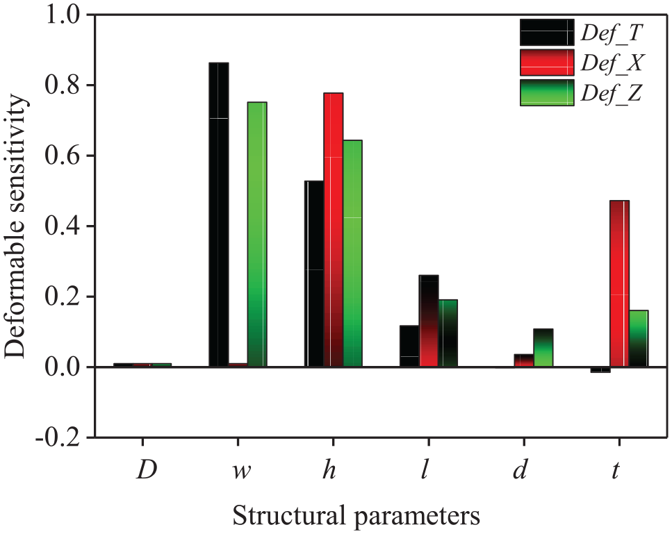
Deformable sensitivity analysis of structural parameters.
Construction and fabrication
Capacitive sensor installation
From the above analysis, six capacitive sensors are utilized to monitor the four-axis force, namely four at the vertical direction for triaxial cutting force and the others at the circumferential direction for torque whose installations are shown in Figure 5. Each capacitive sensor is composed of an upper plate and a lower plate whose distance can be adjusted by an adjusting block. Figure 5(a) and (b) illustrates respectively up and down, and left and right adjustments driven by the adjusting block with the screw. The sensitivity of the capacitive variation with the plates’ distance can be derived as follows based on the Xie et al. 22 :
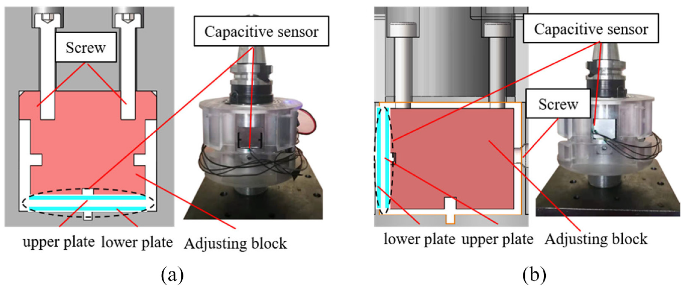
Capacitive sensors’ installation at: (a) vertical direction and (b) circumferential direction.
Where ε0 is the permittivity of vacuum, ε is the relative permittivity of the dielectric material (1.000585 of the air), S is the superposition area of the plates, and d0 is the distance between upper and lower plates.
Then, the sensitivity of each capacitive sensor can be calculated as follows:
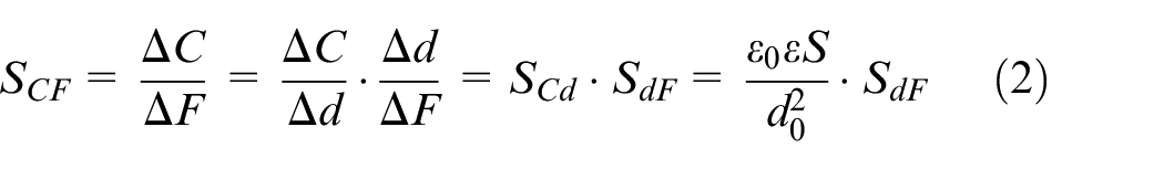
Where SdF is the deformable sensitivity which has been derived from the above analysis, namely Szz, Sxz, and STz.
The plates for vertical deformation detection are rectangular 17 × 15 mm2 in dimension, and the plates for circumferential deformation detection are also rectangular 14 × 12 mm2 in dimension. All the distances between the plates are set to 50 µm. Hence, the simulation sensitivity can be calculated by FEA, which are 1.2 × 10⁻³ pF/N, 5.4 × 10⁻³ pF/N, and 6.3 × 10⁻² pF/N at axial, radial, and torque directions respectively.
Data acquisition and wireless transmission
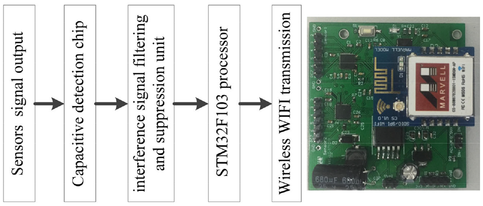
The toolholder dynamometer is always rotating state in the machining process, and traditional wire transmission is difficult to achieve. Therefore, wireless transmission via WIFI is adopted in order to transmit these raw data to Labview software that is installed on the upper computer. Before that, the output signal by the capacitive sensors is detected by the capacitive detection chip and then sent to the interference signal filtering and suppression unit. Then processing signal is sent to a high-speed STM32F103 processor, and then transmits a wireless WIFI modular. The system block diagram of the data acquisition and wireless transmission unit is shown in Figure 6. The referred voltages for the whole system are respectively 5 and 3.3 V. Hence, a voltage of 7.4V is utilized by connecting two lithium batteries in series, and the voltages of 5 and 3.3 V are obtained by DC-DC voltage convert circuit.
Data acquisition and wireless transmission unit.
Integrated construction and fabrication
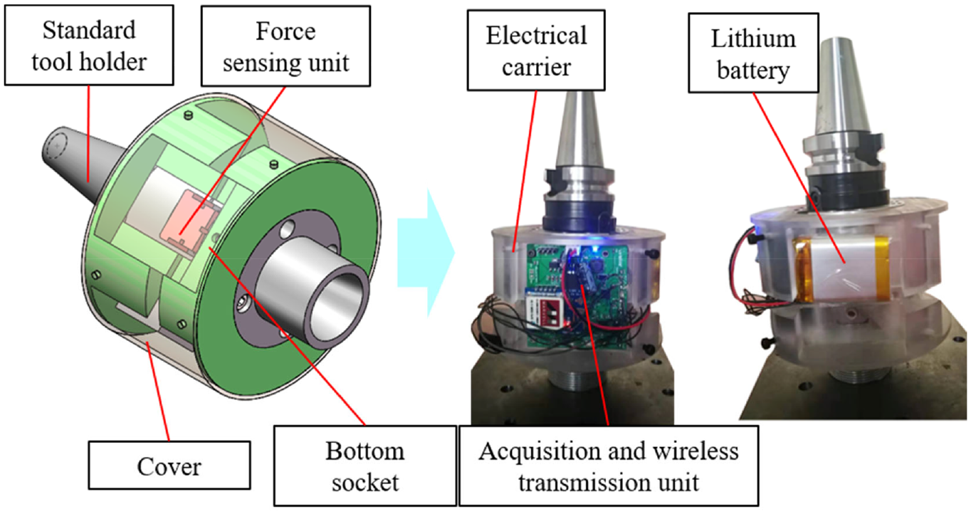
An integrated toolholder dynamometer was manufactured and assembled as shown in Figure 7, which comprised a standard tool holder, an electrical carrier, a force sensing unit, a bottom socket, an acquisition and wireless transmission unit, a lithium battery and a cover. The electrical carrier was used to mount the acquisition and wireless transmission unit and lithium battery. The cover protected the force sensing unit, acquisition and wireless transmission unit, battery from outer cutting chips, cutting fluid, and so on. The force sensing unit could equip different types of standard tool holder, and the bottom socket possessing a standard interface with ER32 collets can assemble multi-size standard tool, which provides a more flexible and reconfigurable machining process.
Manufacture and assembly of toolholder dynamometer.
Test
Static calibration test
The static calibration test was carried out to ensure the accurate relationship between the input load and output signal. A static calibration platform was set up based on a CNC milling machine (Xiangtai VM7032) and a Kistler dynamometer (9257B) as shown in Figure 8. Figure 8(a) to (c) shows the standard force in X, Y, and Z directions was individually loaded by the Kistler dynamometer with an incremental step of 100 N. Because the Kistler dynamometer cannot load torque, an auxiliary device was designed to meet the loading condition of the digital thrust gage (YISIDA type, DS-500N). The force arm was set to 800 mm between two digital thrust gages, so they were loaded with an accurate incremental step of 25 N within the full scale 125 N as shown in Figure 8(d). Therefore, the calibration curves at each direction can be obtained as depicted in Figure 9(a) to (d).
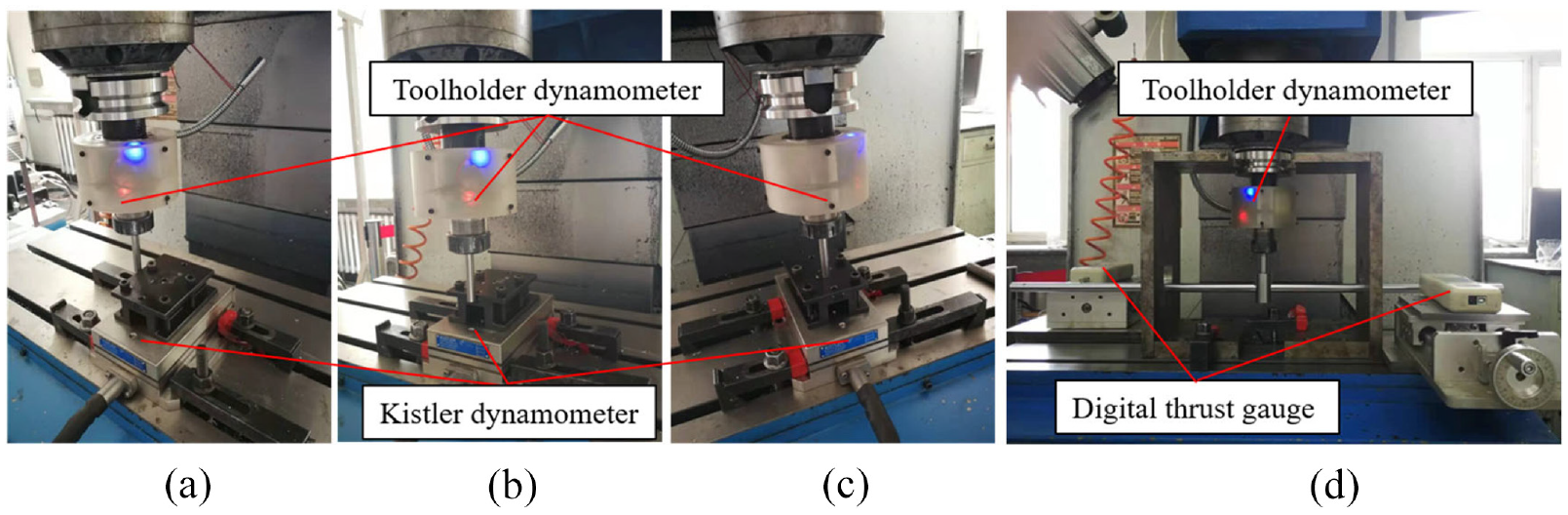
Static collaboration test under: (a) Fx, (b) Fy, (c) Fz, and (d) T.
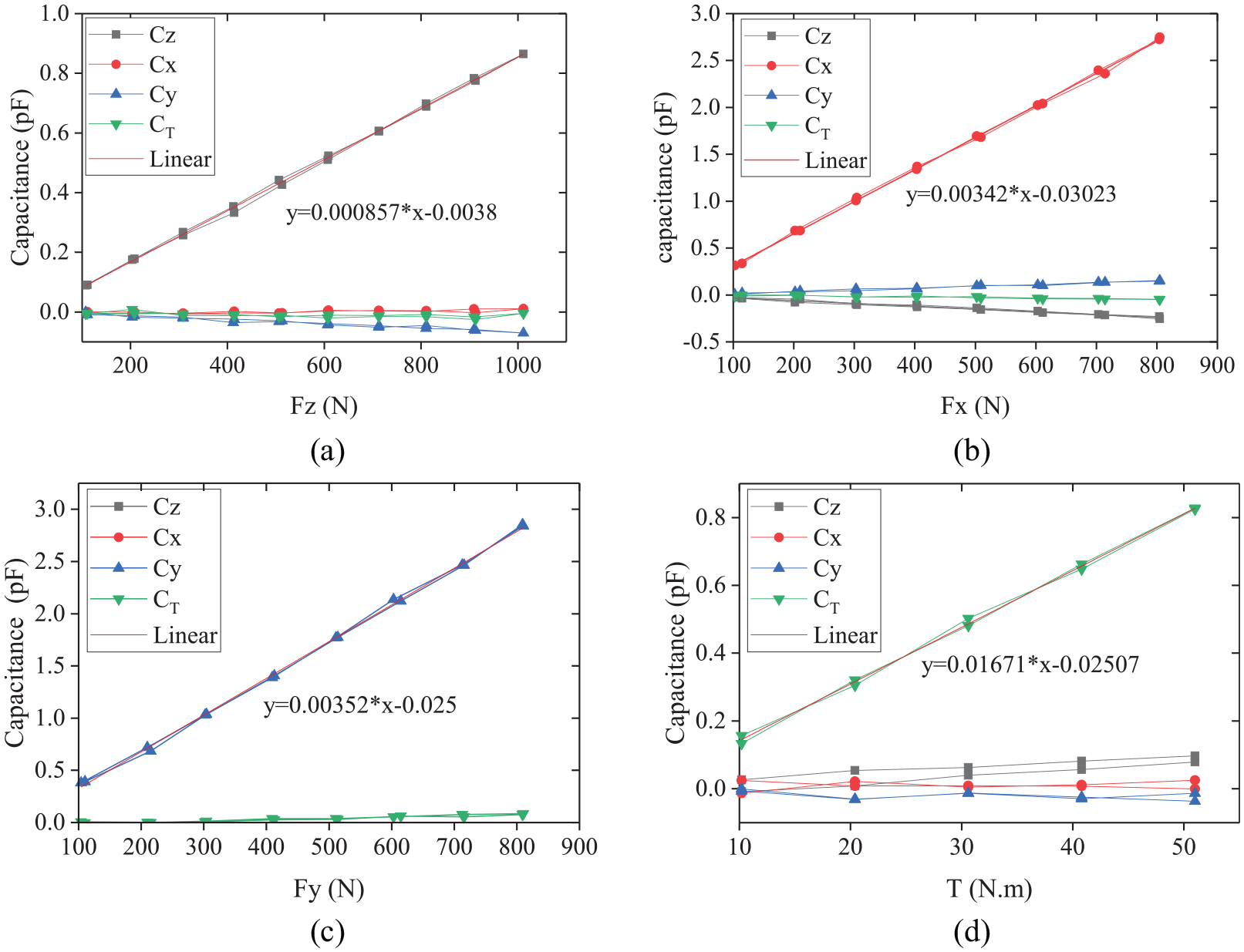
Calibration curves of force and torque: (a) Fz, (b) Fx, (c) Fy, and (d) T.
It can be seen from Figure 9(a) to (d) that the sensitivities of toolholder dynamometer are respectively 857 aF/N, 3420 aF/N, 3520 aF/N, and 16,700 aF/Nm in Fz, Fx, Fy, and T directions, which are superior to Xie et al.’s 23 sensitivities of 571 aF/N, 2302 aF/N, 2353 aF/N, and 11,226 aF/Nm in Fz, Fx, Fy, and T directions, respectively.
Dynamic calibration test
Thanks to the dynamic nature of cutting force, the dynamic response of the cutting system should be considered, which is affected by the natural frequency of cutting system. This can be determined by the CNC machine, toolholder dynamometer and standard tool, which can be obtained by a frequency response function (FRF) based on modal test and analysis. Hence, the toolholder dynamometer clamped a standard tool and was mounted on the CNC machine (Xiangtai VMC7032). According to the referred, 17 the lower natural frequency appears in the radial direction, which determines the maximum speed of the cutting system. Therefore, to obtain the minimum natural frequency, two accelerometers (PCB352C33 type, sensitivity 100 mV/g) with measurement bandwidth of 0.5–10 kHz were arranged in the radial direction of a tool, namely X direction and Y direction. A modal impact hammer (Longke type LK1427, sensitivity 4.19 pC/N) excited the end position of a tool as shown in Figure 10(a).
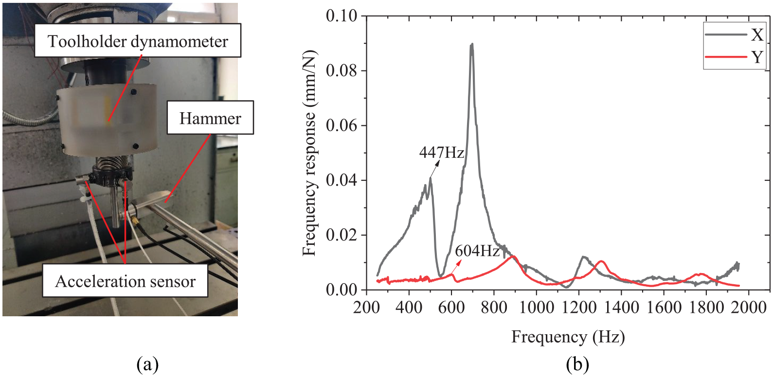
Modal test: (a) pulse test and (b) curve of FRF.
In the modal test, the method of single-point incentive was used to obtain the FRF of machining system. Thus, the FRFs of radial cutting force were shown in Figure 10(b). It can be observed from Figure 10(b) that the natural frequencies of the cutting system including the toolholder dynamometer, tool and machining spindle are 447 and 604 Hz in Fx and Fy directions respectively, which is superior to Ma et al. 15 and Albrecht et al. 9 in whose work the results are around 400 Hz. Hence, the minimum natural frequency (fn, Hz) is 447 Hz which should be at least three times the tooth passing frequency (fe, Hz) that is determined by the spindle speed (n, rpm). The above relationship can be expressed as follows:
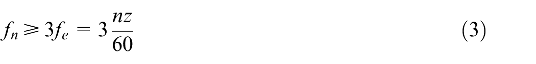
Where z is the teeth number of the cutting tool, the maximal spindle speed can reach 3000 rpm for a three-tooth milling tool.
Cutting experiment
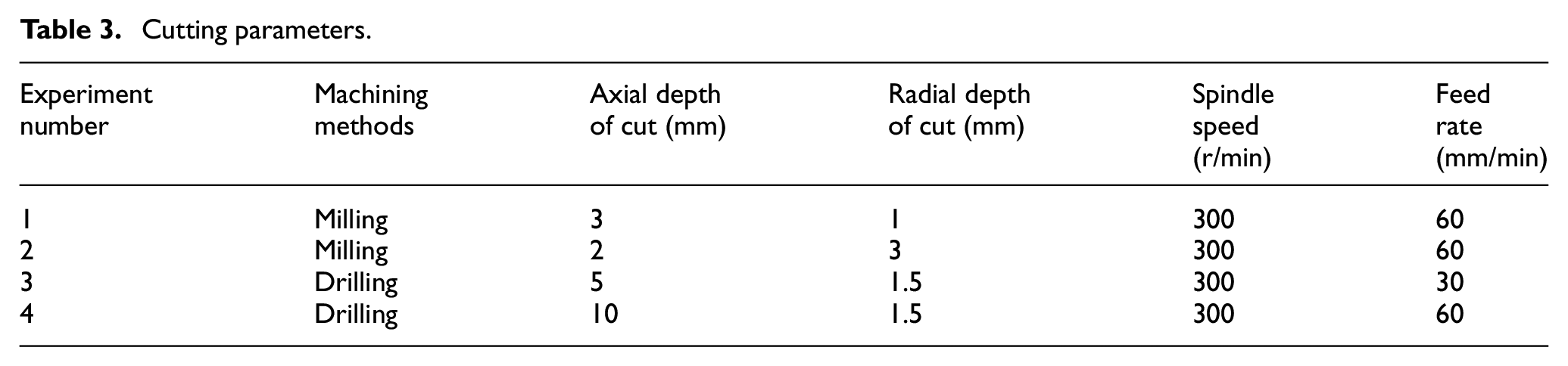
To validate the performance of the toolholder dynamometer, four cutting tests were conducted in a vertical CNC machine. The workpiece material is 7075 aluminum alloy, which is cut by a milling cutter with a diameter of 16 mm, an overhang of 60 mm, a total length of 100 mm, a helix angle of 45°, and three teeth. The cutting force were simultaneously recorded by the referred dynamometer (Kistler 9257B) and the developed toolholder dynamometer. Here, two machining methods, namely, milling and drilling, have been conducted whose cutting parameters are shown in Table 3.
Cutting parameters.
Milling validation
In the milling process, the toolholder dynamometer was always rotating. Thus, the radial cutting force between the rotary coordinate system of the toolholder dynamometer and the fixed coordinate system of Kistler dynamometer has the following relationship:
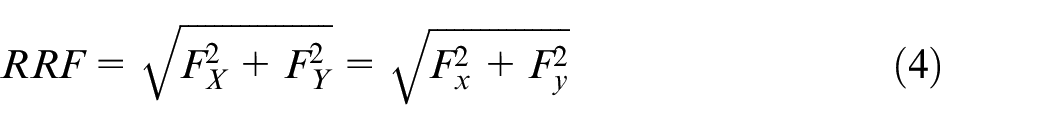
Where RRF refers to the radial resultant force, Fx and Fy represent the radial force sensed by the toolholder dynamometer, FX and FY represent the radial force sensed by the Kistler dynamometer. The radial resultant forces between them are compared as shown in Figure 11. It can be observed from Figure 11(a) and (b) that the waveform change trends between them are consist in the whole milling process. To further validate this truth, we take out two-cycle signals for comparison. Moreover, it is not difficult to find that the detailed waveforms between them basically coincide. In one cycle, the amplitudes of the two waveforms are quite different, which may be caused by runout of the processing system.
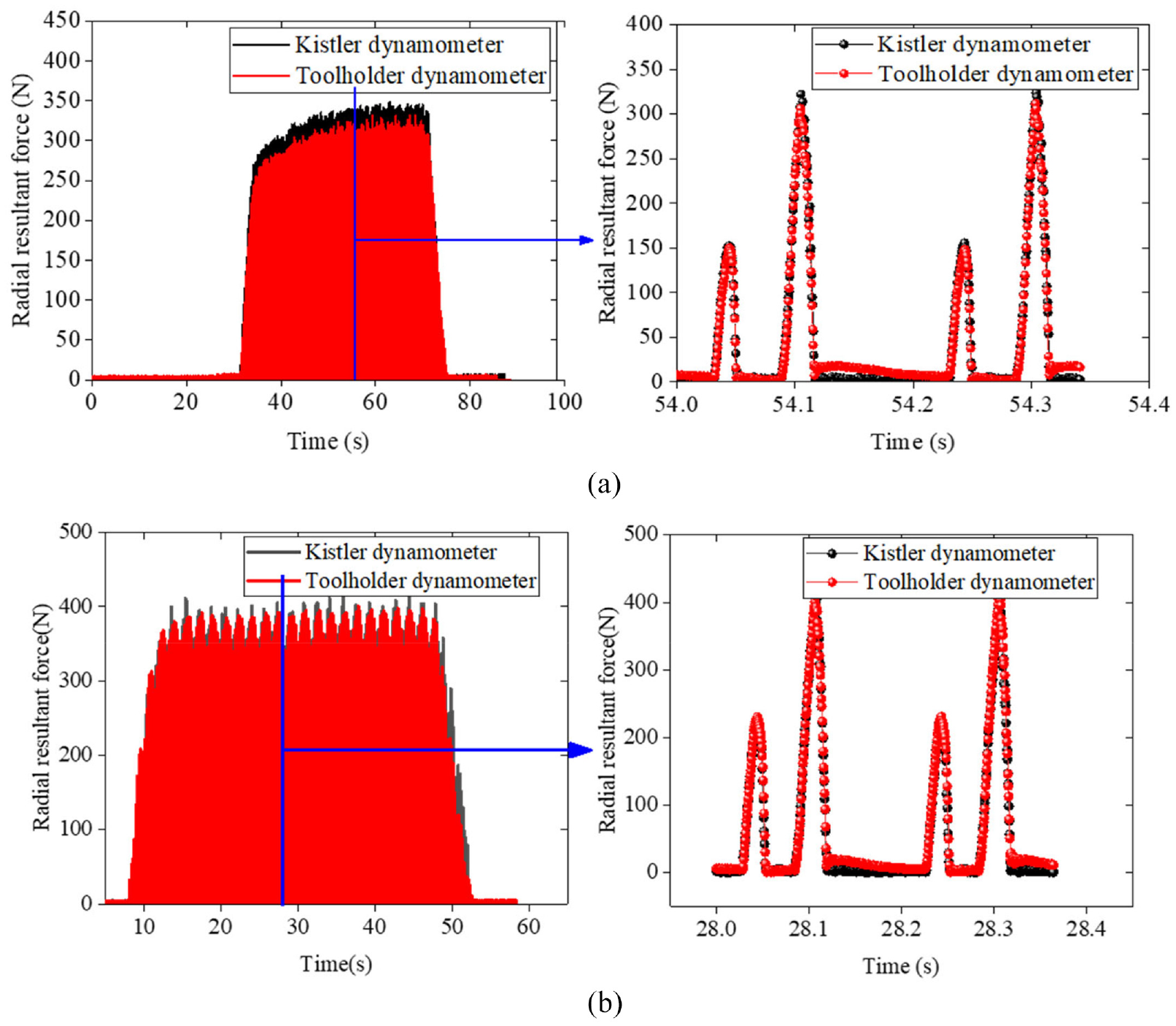
Comparison of radial resultant force: (a) milling test 1 and (b) milling test 2.
To quantitatively evaluate the difference between them, the maximum error and mean error are introduced and defined as follows:
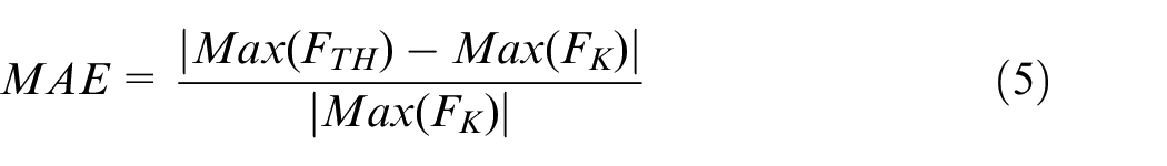
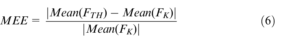
Where Max refers to the maximum value, |·| represents the absolute value, Mean refers to the mean value, FTH and FK are measured by the toolholder dynamometer and Kistler dynamometer.
Based on the formula (5) and (6), the maximum error and mean error of radial resultant force can be respectively calculated as 3.81% and 6.51% for milling test 1, 2.13% and 9.57% for milling test 2.
Drilling validation
Because Kistler 9257B could not monitor the torque in the milling process, two drilling tests were conducted to validate the characteristic of torque T and axial force Fz as illustrated in Figure 12. It can be observed from Figure 12(a) and (b) that the waveform changes of torque T and axial force Fz possess good consistency between toolholder dynamometer and Kistler dynamometer. According to the equations (5) and (6), the maximum error of torque T and axial force Fz can be obtained as 3.62% and 1.81% for drilling test 1, 6.75% and 2.57% for drilling test 2. Meanwhile, the mean error of torque T and axial force Fz can be obtained as 0.95% and 13.24% for drilling test 1, 9.31% and 8.68% for drilling test 2.
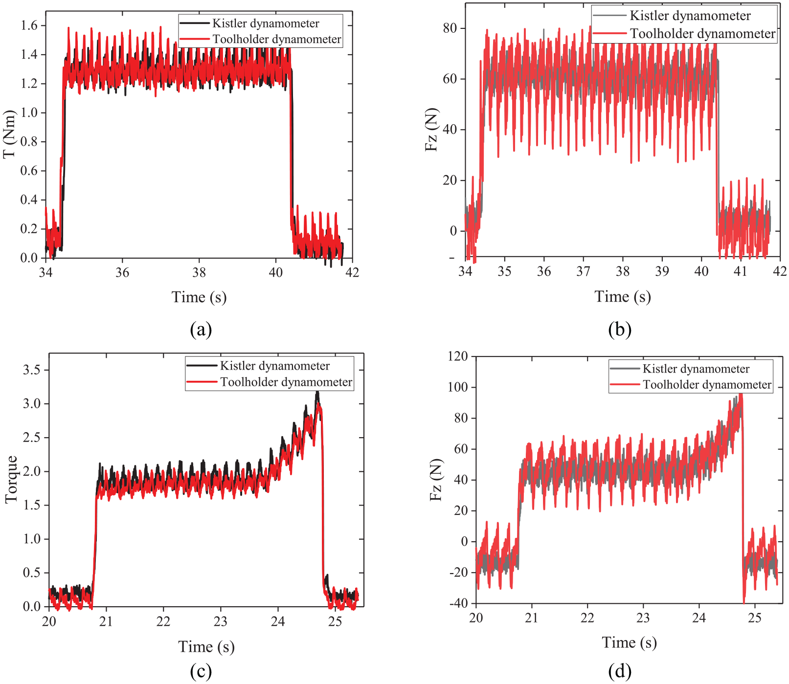
Comparison of torque T and axial force Fz: (a) torque T for drilling test 1, (b) axial force Fz for drilling test 1, (c) torque T for drilling test 2, and (d) axial force Fz for drilling test 2.
It can be concluded from the above analysis that the toolholder dynamometer has good measuring performance. Compared to the Kistler dynamometer, its mean error of 13.24% occurs in axial direction and the others do not exceed 10%.
Conclusion
In this paper, a toolholder dynamometer based on six capacitive sensors was developed. On the one hand, it took advantage of split structure, which provides higher flexibility and reconfigurability. On the other hand, a novel method of adjusting distance between two plates was adopted, that is, the distance between two plates in the horizontal and vertical directions was adjusted separately, which makes it easier to mount these sensors. Finally, a force sensing unit and a bottom socket, an acquisition and wireless transmission unit, a lithium battery, a cover were installed and debugged as a whole system. A series of tests were completed and the conclusions were as follows:
The static calibration results show the tool holder dynamometer has high sensitivities with 0.857 × 10⁻³ pF/N, 3.42 × 10⁻³ pF/N, 3.52 × 10⁻³ pF/N at Fz, Fx, Fy directions and 1.67 × 10⁻² pF/Nm at T directions.
The model test results illustrate that the natural frequencies of the cutting system including the toolholder dynamometer, tool and machining spindle are 447 and 604 Hz in Fx and Fy directions respectively. The maximal spindle speed can reach 3000 rpm for a three-tooth milling tool.
The cutting experiment shows demonstrates the toolholder dynamometer has good measuring performance. Compared to Kistler dynamometer, its maximum error is 13.24% occurring in axial direction and the others do not exceed 10%.
Footnotes
Declaration of conflicting interests
The author(s) declared no potential conflicts of interest with respect to the research, authorship, and/or publication of this article.
Funding
The author(s) disclosed receipt of the following financial support for the research, authorship, and/or publication of this article: This work was supported by the National Key Research and Development Program of China (2018YFB1306803)