
Abstract
Thin-walled parts with curved surface are widely used in industrial applications and the high-quality machining is still a major problem because of the low stiffness. By using the machining-path obtained from the design model of thin-walled parts with curved surface, the machining accuracy requirement may easily not be met due to the springback of clamping deformation when the machining process is finished. It is a novel idea that when the machining-path mapping from free-state to clamped-state is realized based on the clamping deformation, the final machining-path of thin-walled parts can be re-designed to directly ensure the machining accuracy requirement after the fixture is released. Based on the concomitant thought of curved surface and the elastic deformation theory of thin shell in this study, the mathematical model for the machining-path mapping from free-state to clamped-state is established for the thin-walled parts with curved surface. Then, the corresponding relationship of cutter contact (CC) points is calculated by grid mapping. Finally, the machining-path for the thin-walled parts with curved surface is re-designed under the clamped-state. Taking a thin-walled cylinder workpiece as an example, the experiment results show that the proposed method can achieve the avoiding purpose for the machining error caused by clamping deformation. These research achievements are of vital importance for realizing high-quality machining of the thin-walled parts with curved surface.
Keywords
Introduction
With the rapid development of aerospace equipment, automobile mold, and other fields, thin-walled parts with curved surface have been widely concerned due to small mass and high specific strength. For the high machining requirement, the high-quality machining of thin-walled parts with curved surface is still a major problem because of the low stiffness and the workpiece deformation during machining severely affects the machining accuracy. 1 Especially for the fixture-workpiece-cutter system, Li and Melkote 2 have long before found that the ideal relative position between workpiece and cutter would be easily destroyed due to the low stiffness of the thin-walled parts under the action of clamping force, and Prabhaharan et al. 3 have indicated that 20%–60% of the machining error was caused by the clamping deformation. For some cylindrical and conical thin-walled parts, there are no special clamping positions, such as the foundation base. So it is very necessary to reduce and control the clamping deformation of thin-walled workpiece. Some researchers, such as Wang et al., 4 have studied the finite element analysis and control method of clamping deformation mechanism for the thin-walled shell workpiece. It is known that the clamping deformation is obvious unavoidable for the thin-walled parts with curved surface even if some customized clamping devises are used to guarantee the local stiffness of the clamping position. Especially for machining the cylindrical or conical thin-walled parts, because of the different size of thin-walled parts, even if the special fixtures such as the v-shaped blocks are used and the problem of clamping deformation still exists. In this way, by using the machining-path obtained from the design model, the machining accuracy requirement may easily not be met due to the springback of clamping deformation when the machining process is finished. Therefore, it is an important issue to reduce the machining error caused by clamping deformation, so as to achieve high-quality processing for the thin-walled parts with curved surface.
Aiming at the machining error of thin-walled parts induced by clamping deformation, lots of researches have been carried out. The research work mainly includes two aspects, just clamping layout optimization, deformation prediction and compensation. In order to minimize the clamping deformation and enhance the machining accuracy, Qin et al. 5 established a workable finite element model with multi-fixturing layout, which improves the calculation efficiency for prediction control and provides a fixturing layout design method for the thin-walled workpiece. Sánchez et al. 6 analyzed three main errors caused by fixture through the comprehensive analysis of position/deformation, then the CAD model of workpiece after modification was got by synthesizing these error values and the new toolpath to compensate the errors was produced. Jayaram et al. 7 proposed a method for the deformation calculating at machining point by using the Jacobian matrix. Siebenaler and Melkote 8 analyzed the influence of the friction coefficient between workpiece and fixture, and the mesh element size on the workpiece clamping deformation, and then the validity of finite element simulation was verified by experimental results. Ratchev et al. 9 proposed a finite element (FE) model of the fixture-workpiece system which was well-suited for the elastic deformation predicting of workpiece. Qin 10 put forward the method of analysis-prediction-control for the clamping deformation based on neural network and genetic algorithm, and the prediction model of clamping deformation was suggested according to the training samples. Dong et al. 11 presents a contribution for predicting the machined surface errors where fixture-workpiece system dynamic effects during milling process are considered. Kaya 12 present a method to optimize fixture layout by genetic algorithms (GAs). Qin et al. 13 investigated a planning method of fixturing layout for the workpiece based on surface discretization and genetic algorithm. Dong and Ke 14 analyzed the clamping deformation between thin frame and contact element by the finite element method, and revealed the influence rule of locator position, clamping sequence, and loading way on the clamping deformation. Chen et al. 15 studied the springback deformation of workpiece under the external force and established a finite element compensation model by improving machining-path and choosing complete compensation and optimizing compensation. In order to improve the machining accuracy of thin plate-shape part in face milling, Yi et al. 16 presents a novel method for compensating the surface errors by prebending the workpiece during the milling process. Zhou et al. 17 established the mathematical model for workpiece clamping deformation and the finite element analysis model for clamping system, and then an active compensation method was proposed based on the error prediction. Zhou 18 also studied the clamping error and its active control method.
Based on the above researches, it can be found that most scholars reduce the machining error mainly by controlling or reducing the clamping deformation of the thin-walled parts. And some researches are carried out to predict the model after clamping deformation and the machining-paths are generated according to the predict model. However, the clamping deformation is obvious unavoidable for the low stiffness of thin-walled parts with curved surface, directly resulting in the difference between surface shape in free-state and that in clamped-state. So the machining-paths obtained from the design model are not suitable for the processing of thin-walled curved parts with clamping deformation. And the machining-paths generated by the predict model may not meet the machining accuracy requirement due to the springback of clamping deformation when the machining process is finished. In order to solve this problem effectively, a machining-path mapping method from free-state to clamped-state is proposed for thin-walled parts with complex curved surface in this paper, which can ensure the machining accuracy requirement after the fixture is released. While the research on this issue is seldom mentioned.
As a consequence, the research on the springback deformation for workpiece is carried out after the release of clamping force in this study. Different from the conventional prediction of clamping deformation, the main goal and innovation for this study is to obtain the machining-path mapping matrix relationship between the clamped-state and the free-state. And then the machining-path of the thin-walled parts in free-state is directly mapped to the clamped-state, so as to avoid the machining precision error caused by the springback deformation. Considering that the online measurement method of CMM can measure the deformation of the workpiece, it is difficult to obtain the local deformation of the machining area, especially the deformation of machining-path. So the online CMM cannot be applied to predict the deformation of the machining-path. In order to predict the machining-path after deformation, the offline finite element simulation method is used in this study to obtain the mapping relationship between the clamped-state and free-state, so the machining-path in the free-state is mapped to the clamped-stated more accurately. Firstly, based on the concomitant thought of curved surface and the elastic deformation theory of thin shell, the mathematical model for the machining-path mapping from free-state to clamped-state is established for the thin-walled parts with curved surface. Then, the corresponding relationship of cutter contact (CC) points is calculated by grid mapping. Finally, the machining-path for the thin-walled parts with curved surface is re-designed under the clamped-state, so as to achieve the avoiding purpose for the machining error caused by clamping deformation. The research achievements will be very important for realizing high-quality machining of the thin-walled parts with curved surface.
The rest of this paper is organized as follows. In Section 2, the theoretical foundation for the clamping deformation of thin shell is introduced, and the mathematical model for machining-path mapping of thin-walled parts is established from free-state to clamped-state. Section 3 presents the calculation process for corresponding relationship of CC points by grid mapping and the generation process for the re-designed machining-path of thin-walled parts with curved surface under the clamped-state. Section 4 conducts the experiment, and the conclusions are summarized in Section 5.
Clamping deformation analyzing of thin shell and machining-path mapping from free-state to clamped-state for thin-walled parts
For thin-walled parts with curved surface, the surfaces in free-state and in clamped-state can be considered as a pair of concomitant surfaces and the clamping deformation is just elastic deformation. In this section, the concomitant thought of curved surface and the elastic deformation theory of thin shell are firstly introduced, and then the mathematical model for the machining-path mapping of thin-walled parts is established from free-state to clamped-state.
Concomitant theory of curved surface
For two regular surfaces as shown in Figure 1, they can be considered as a pair of concomitant surfaces when a point-to-point mapping relationship is established between them. P0 and P are a pair of mapping points, and
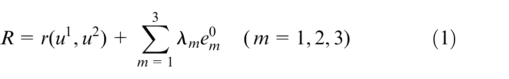
Relationship of a pair of concomitant surfaces.
In which, u1 and u2 represent the orthogonal parametric coordinate curves,
Elastic deformation theory of thin shell
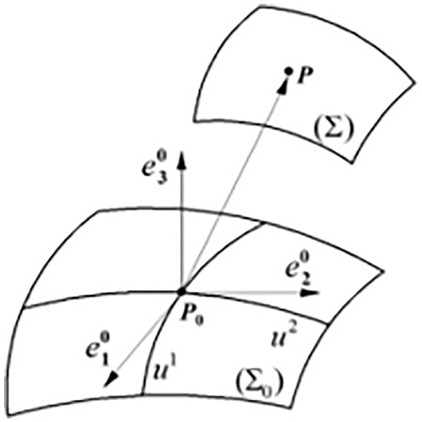
According to the basic hypothesis of thin shell theory, the space orthogonal curvilinear coordinate system αβγ on the middle surface of thin shell (α and β are the principal curvature curves for middle surface, γ is the straight normal line pointing to the convex direction for middle surface) is established, as shown in Figure 2. For a certain point M on the middle surface, A and B are defined to represent the Lame coefficients in the two directions, k1 and k2 represent the principal curvature, R1 and R2 represent the corresponding principal curvature radius, μ, ν, and ω represent the displacement components along the three coordinate axes in space orthogonal curvilinear coordinate system. Assuming that the displacement of points with the same values of α and β in the elastic body is expressed as u1, u2, and u3 along the three coordinate axes in space orthogonal curvilinear coordinate system, the relation equation between the displacement at any point P in thin shell and the displacement of middle surface can be deduced as
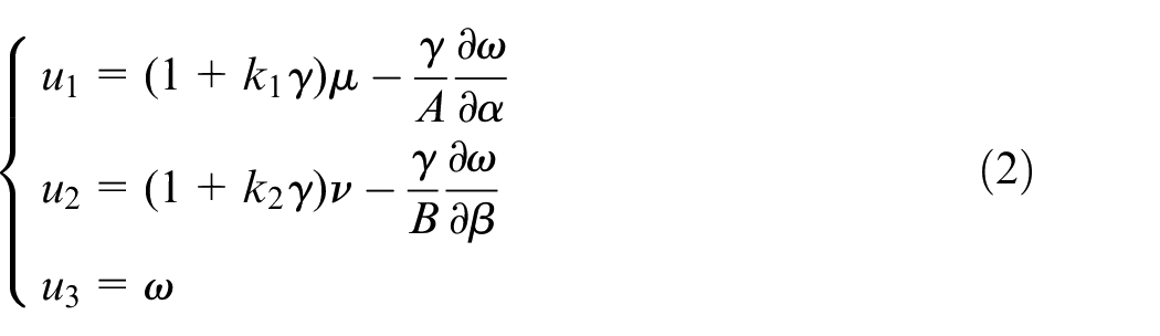
Space orthogonal curvilinear coordinate system.
It is known that the displacement components at any point in thin shell can be expressed by the displacement at the corresponding position on middle surface, so the whole deformation of thin shell can be obtained by solving the displacement for middle surface. It can be also found from the relation equation that P and M are a pair of normal mapping points before deformation, P1 and M1 are still a pair of normal mapping points after deformation, and the distance between normal mapping points keeps constant.
Machining-path mapping from free-state to clamped-state
Based on the concomitant thought of curved surface and the elastic deformation theory of thin shell, a sketch figure for the surface deformation mapping is shown in Figure 3. e1 and e2 are the tangent vectors of middle surface in free-state (
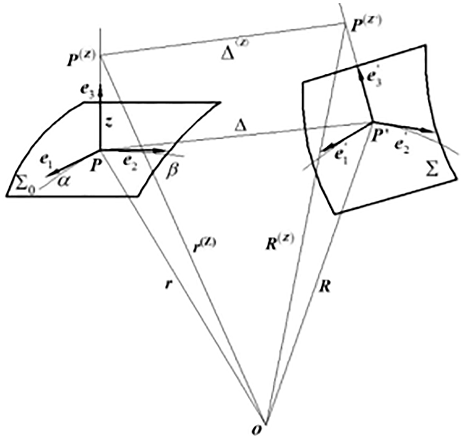
Sketch figure for surface deformation mapping between free-state and clamped-state.
From the above analysis, the equation of surface (

And in the same way, the equation of surface (

Based on the above and setting the CC surface of thin-walled parts with curved surface as the research object, the CC point mapping relationship is considered as f from free-state to clamped-state. For the ball-end cutter, the CC point-group in free-state Dm = {(xem, yem, zem)| m = 1,2,3…q} (q is the number of CC points), the cutter location (CL) point-group in free-state is as

In which, Rt is the tool radius and

And the CL point-group of thin-walled parts in clamped-state is as

In which,
According to equations (5)–(7), the CL point mapping relationship for the thin-walled parts from free-state to clamped-state is as

It can be found that equation (8) is just the mathematical model for the machining-path mapping from free-state to clamped-state for the thin-walled parts with curved surface.
Machining-path re-designing forthin-walled parts in clamped-state
From Section 2, the CL point mapping from free-state to clamped-state is presented for thin-walled parts with curved surface, and it can be found that the key issues to solve the CL point in clamped-state are to solve the mapping relation f and the unit normal vector
It should be well known that the process for solving the CC point in the clamped-state is essentially the mapping process for the mesh of CC point from the free-state. In this way, the surface shape of the thin-walled parts after deformation should be known firstly. As the finite element method is now a more mature solution, it is used to solve the clamping deformation. After calculating the CC point of thin-walled parts before and after clamping deformation and the finite element mesh unit in which the CC point is located, the position relation for the CC point in free-state with respect to the finite element unit is determined, and then the CC point formed with the clamping deformation of finite element unit can be calculated according to the position relationship. Based on the finite element analysis for clamping deformation in this section, the calculation process for mapping relation f is first given by the grid mapping of CC point. After solving the unit normal vector
CC point mapping for thin-walled parts fromfree-state to clamped-state
In the finite element analysis, there is a one-to-one correspondence relation between the mesh units and the mesh nodes before and after clamping deformation for the thin-walled parts with curved surface. The mapping rule is as following, just that the mesh units in which the CC points are located are the same before and after deformation, and the positions of CC points are similar in the respective mesh units before and after deformation.
The position of the CC point in the finite element model may appear in three situations, just that the CC point is within the mesh unit, the CC point is on the edge of mesh unit, and the CC point is just at the mesh node. According to the position of the CC point in finite element model under the free-state of thin-walled parts, the calculation for the CC point coordinates of thin-walled parts in clamped-state and the mapping relation f in each case are as following.
CC point within mesh unit
In the finite element analysis, the common finite element mesh unit is triangular element or quadrilateral element, and the quadrilateral element can be converted into the triangular element. For triangular element, the area coordinates are used to represent the position of inner points in the mesh unit as shown in Figure 4.
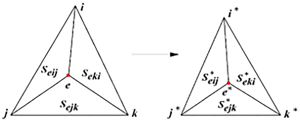
CC point within mesh unit.
The CC point e is in the directed triangular element
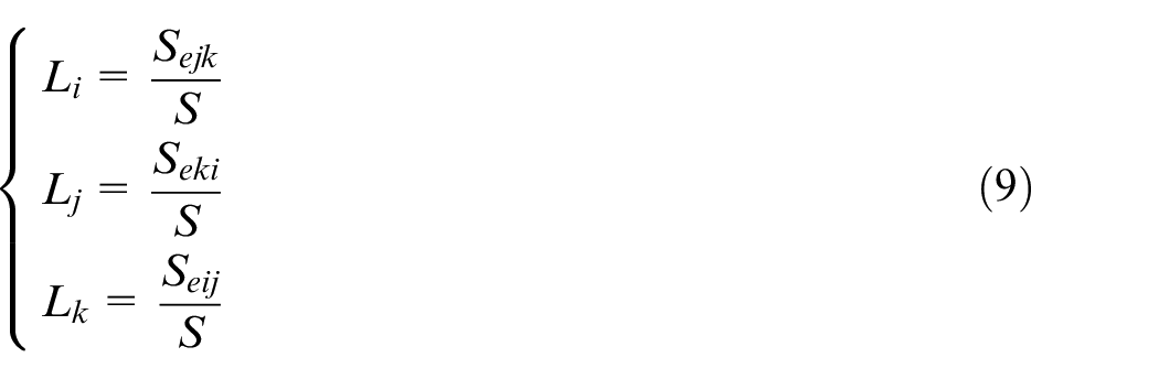
In which, i, j, and k are the finite element mesh nodes of the directed triangular element, and are arranged in anticlockwise, S is the area of
The mapping mesh unit corresponding to
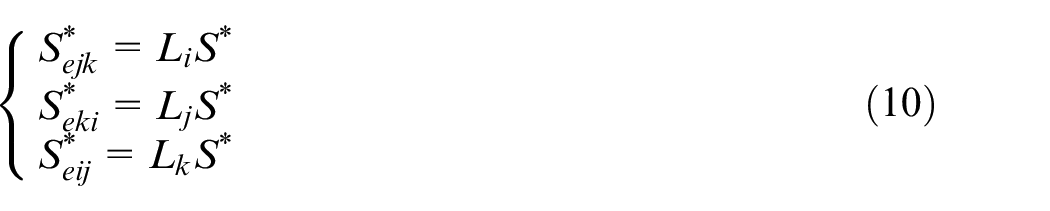
In which, i*, j*, and k* are the finite element mesh nodes of the directed triangular element in the clamped-state, S* is the area of
Define a directed triangle
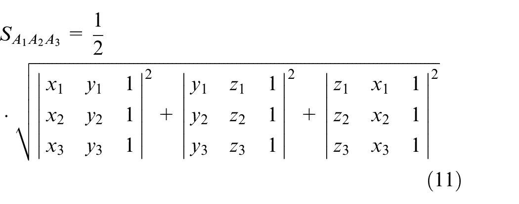
The area of the directed triangle formed by any point A(x, y, z) within
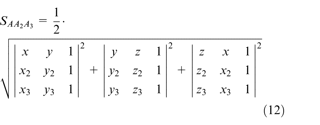
According to equations (9)–(12), when the coordinate of CC point is e(xe ye, ze, 1) and the coordinates of the corresponding mesh nodes i, j, k are (xi, yi, zi, 1), (xj, yj, zj, 1), (xk, yk, zk, 1), the area coordinate of CC point, just the e(xe ye, ze, 1), is as
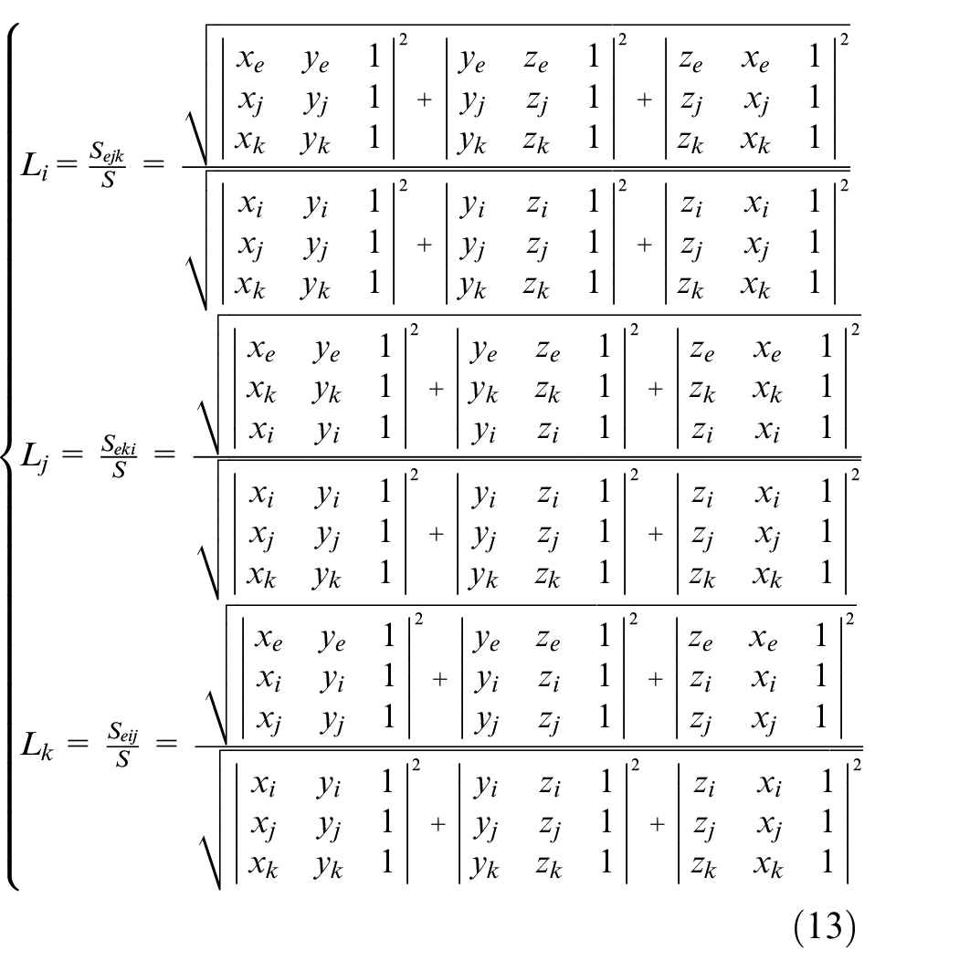
The conversion from the area coordinates to the Cartesian coordinates is as
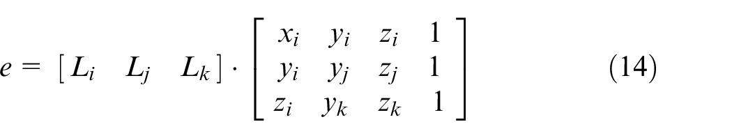
Therefore, the coordinate of the CC point
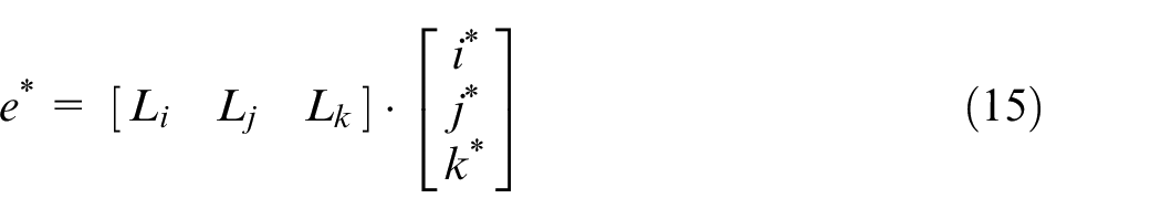
In which, the coordinates of the corresponding mesh nodes i*, j*, k* are
Based on the finite element analysis for clamping deformation, the deformation matrices Ti, Tj, Tk of mesh nodes i, j, k are as

Let [Li Lj Lk] = h(e, i, j, k), in which h represents the function relation as equation (13). In this way, the mapping relation f between CC point in the free-state and that in the clamped-state is as

CC point on edge of mesh unit
As shown in Figure 5, the CC point e of thin-walled parts in free-state falls between mesh nodes i and j, and the i* and j* are the corresponding mesh nodes for thin-walled parts in clamped-state.
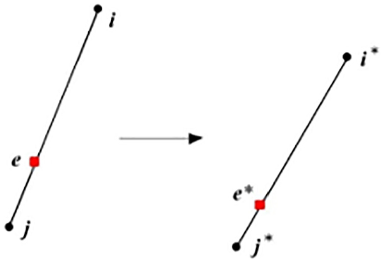
CC point on edge of mesh unit.
In this way, there is a proportional coefficient λ between e and i, j, just as
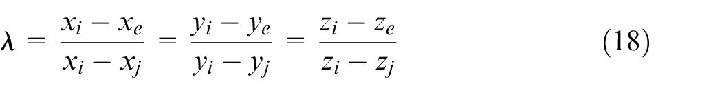
In which, (xe, ye, ze, 1) is the coordinate of CC point e, (xi, yi zi, 1) and (xj, yj, zj, 1) are the coordinates of mesh nodes i and j, respectively.
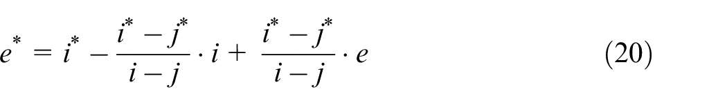
As the proportional coefficient is constant, the coordinate of CC point e* for thin-walled parts under clamped-state is as
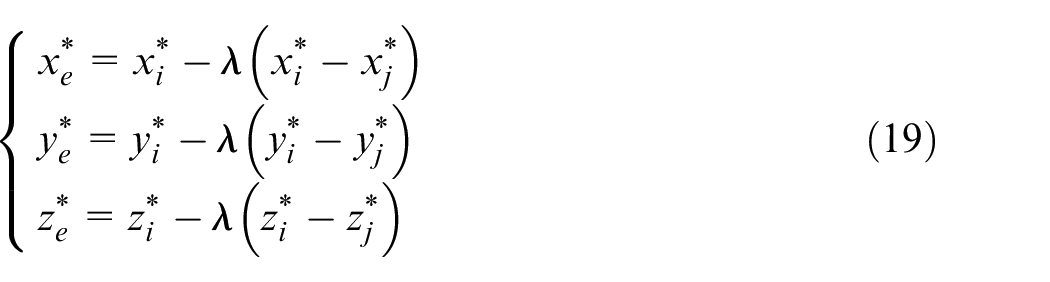
That is
In which,
E is a unit matrix as
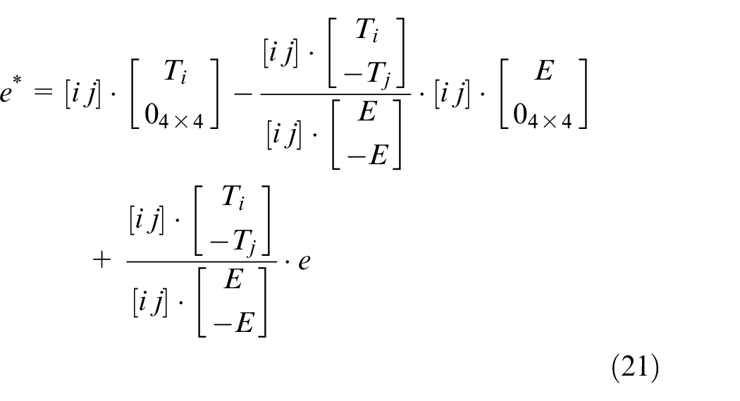
Simplify as
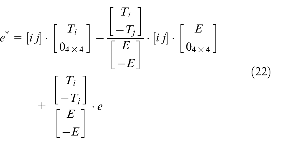
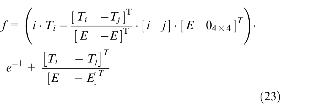
In this way, the mapping relation f between CC point in free-state and that in clamped-state is as
CC point at mesh node
The CC point e of thin-walled parts in the free-state falls at the mesh node i, and i* is the corresponding mesh node for thin-walled parts in the clamped-state. According to the one-to-one correspondence between the nodes for thin-walled parts before and after deformation, the coordinate of CC point e* for thin-walled parts under the clamped-state can be got as

It can be found that the mapping relation f between CC point in free-state and that in clamped-state is as

Unit normal vector solving of corresponding CC point for thin-walled parts in clamped-state
In this section, the method based on local least square surface fitting is proposed to solve the unit normal vector
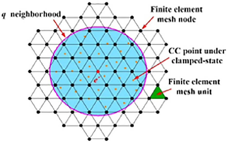
q neighborhood of CC point e*.
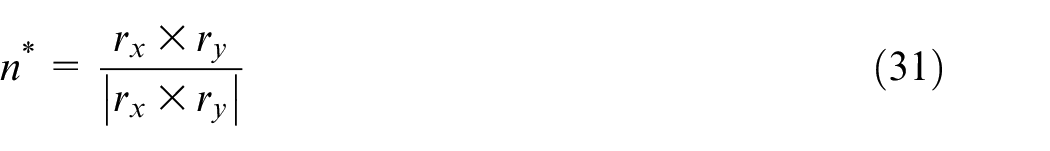
For a certain CC point e*, its unit normal vector
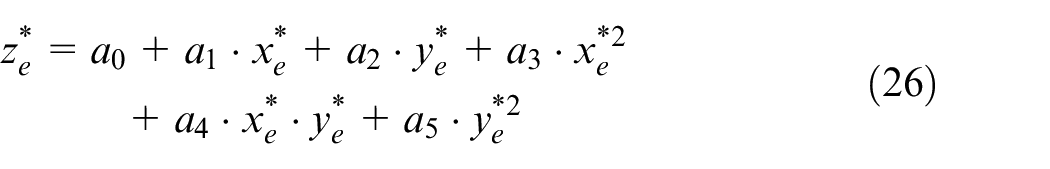
In which, a0, a1, a2, a3, a4, a5 are the fitting coefficients. The CC points of thin-walled parts under the clamped-state
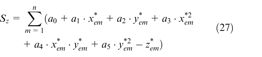
It should be satisfied as
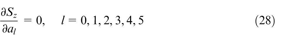
That is just to satisfy the linear equations as
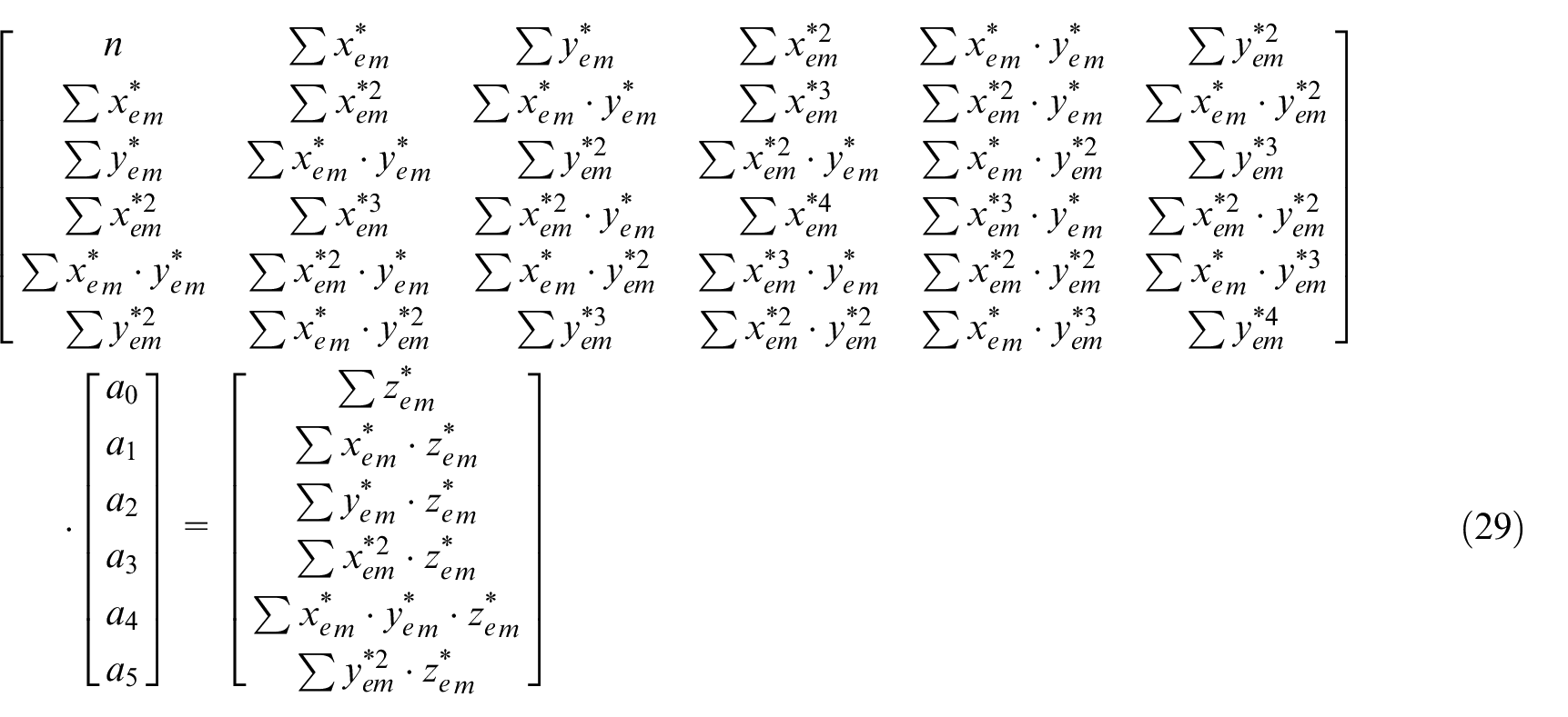
After solving equation (29), the local least square surface can be transformed to the parametric form as
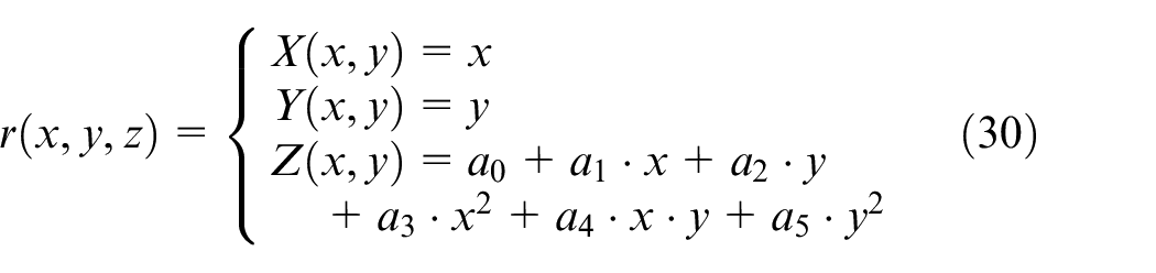
The partial differential ∂r/∂x, ∂r/∂y of the local least square surface r(x, y, z) can be solved by equation (30) as
Generation process for re-designed machining-path of thin-walled parts under clamped-state
After solving the mapping relation f, the CC point under the clamped-state can be obtained by the grid mapping. However, the CC point cannot be directly used to machine the thin-walled parts with curved surface. It is necessary to complete the conversion from CC point to CL point and the connection of machining-path point. The cutter nose point is often used as the CL point in NC machining, and the relationship between CC point and CL point is as

In which,
In this way, based on the CL point mapping relationship for thin-walled parts from free-state to clamped-state in Section 2, the CL point of thin-walled parts under the clamped-state is obtained by the solving results of mapping relation f and unit normal vector
Experiment for proposed method
In this section, experiments are carried out to verify the machining-path mapping for thin-walled parts from the free-state to the clamped-state.
Fixture and clamping-force measuring
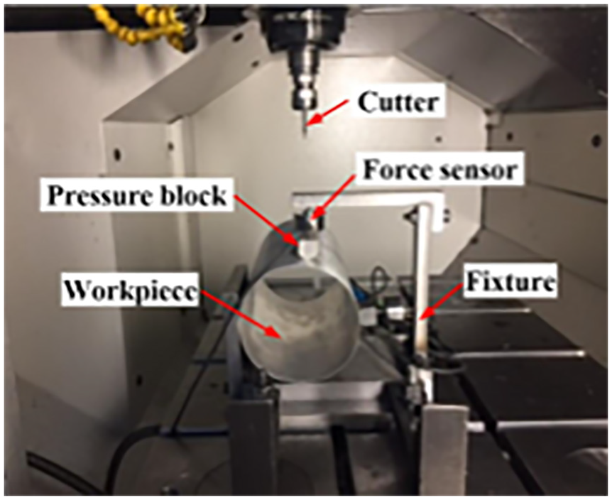
To verify the validity of proposed method, the fixture and the clamping-force for the workpiece should be knew firstly, so as to obtain the surface shape of thin-walled parts after deformation. In this study, 7075 aluminum alloy thin-walled cylinder parts with size of 98 × 1 × 200 mm (Outer diameter × Wall thickness × Length) is used as the test workpiece and in machining process. In order to obtain the clamping force and position, the special fixture and the clamping-force measuring device are adopted as shown in Figure 7.
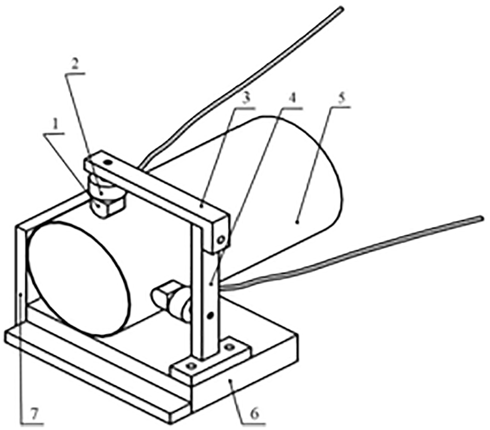
Fixture and clamping-force measuring device (1 – Pressure block, 2 – Force sensor, 3 – Bracket A, 4 – Bracket B, 5 – Workpiece, 6 – Foundation bed, 7 – Locating base).
Foundation bed 6 and locating base 7 are used to limit the freedoms of translation and rotation for the test workpiece and served as a locator. Pressure block 1 and force sensor 2, which are connected with bracket 3 and bracket 4, play the role of providing the clamping force and measuring the clamping force. So the clamping position and the clamping force can be obtained through the special fixture and the force sensors.
Experiment process
Based on the fixture and the clamping-force measuring device, a graphic pattern is machined on the outer surface of thin-walled cylinder workpiece. The ideal geometric model of graphic pattern is established by UG software in the free-state, and the parametric equation for graphic pattern projected on the XY plane is as
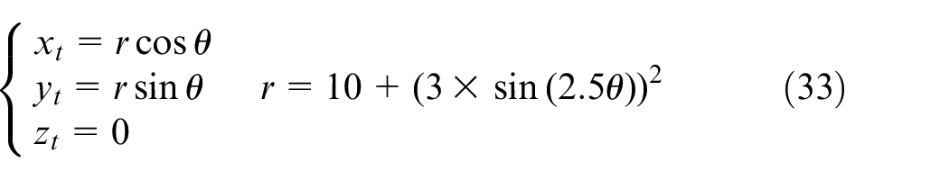
In which, r and θ are the polar radius and the polar angle in polar coordinate for the graphic pattern, and xt, yt, zt are the coordinates in Cartesian coordinate system for the graphic pattern.
Before the experiment of processing thin-walled parts, and according to the clamping force and the clamping position obtained by Section 4.1, it just took several minutes to predict the deformation of thin-walled workpiece by finite element method. And according to Siebenaler and Melkote, 8 the experimental verification of workpiece deformation predicted by the FEA model shows agreement within 5% of the experimental data. So the accuracy of deformation prediction can be guaranteed. And based on the deformation, the machining-path mapping from free-state to clamped-state is obtained according to Section 2. And then the machining-path after deformation on the design model could be obtained by the method of machining-path re-designing for the thin-walled parts in clamped-state proposed in Section 3.
In this study, in order to ensure the contact state between the cutter and the workpiece is consistent before and after the machining-paths mapping, the NS-MSB230 two-edged carbide ball-end milling cutter with diameter of 2 mm is used in machining experiment, and the machining parameters are as spindle speed 5000 rpm, feed speed 200 mm/min, cutting depth 0.3 mm. By using post-processing, CC points and CL points for thin-walled parts in free-state are obtained with the residual height of 0.005 mm.
It can be seen from Zhou
18
that the milling force along the z axis is smaller compared with the x and y direction during ball-end cutter milling, which can be ignored. According to the empirical formula of cutting force, the cutting force is negligible compared with the clamping force due to small cutting depth. And the deformation caused by axial force can be ignored compared with the deformation caused by clamping force. In the experiment, only the clamping deformation is considered and the deformation caused by cutting force is ignored. According to the actual clamping layout as shown in Figure 8, the ANSYS software is used to analyze the neutral shell of the thin-walled cylinder parts, so as to obtain the deformation matrices of mesh nodes and the unit normal vector
Actual clamping layout.
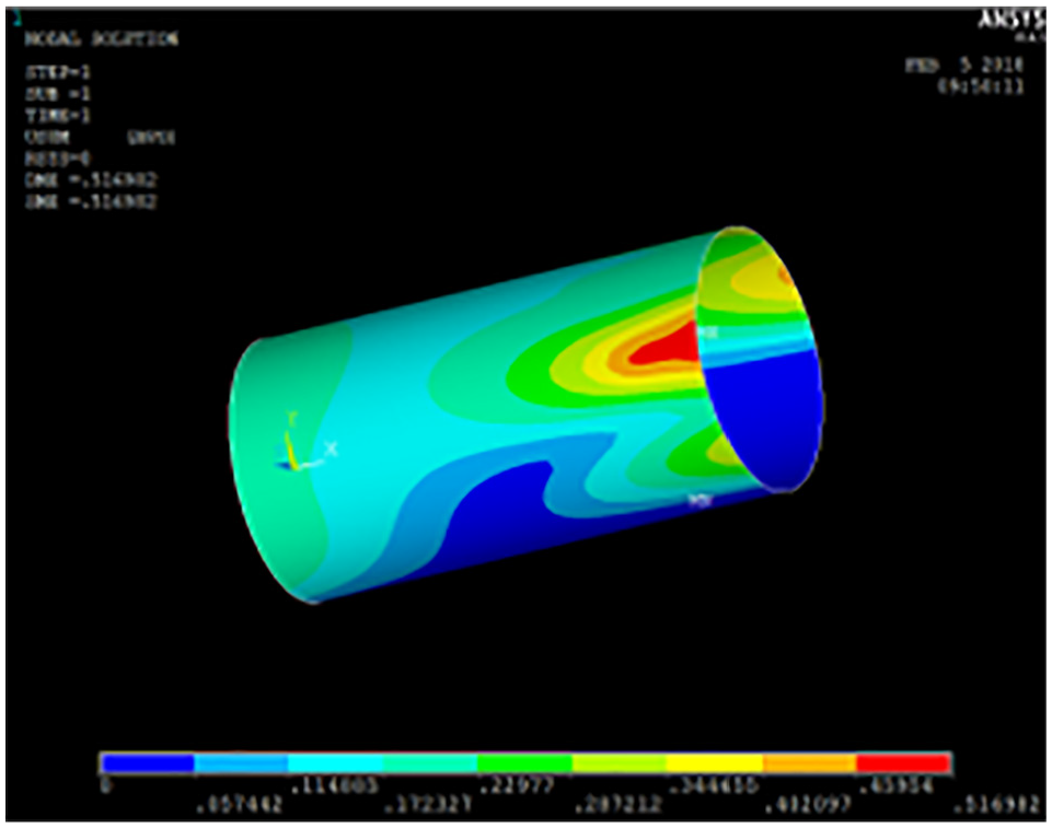
Result of finite element analysis.
Based on the above, the deformation matrices of mesh nodes can be obtained. By combining the CC points in free-state, the mapping relation f is obtained according to equations (17), (23), and (25). Then the CC points under clamped-state are calculated as shown in Figure 10, which would be used in the final experiment for verifying the proposed mapping relationship.
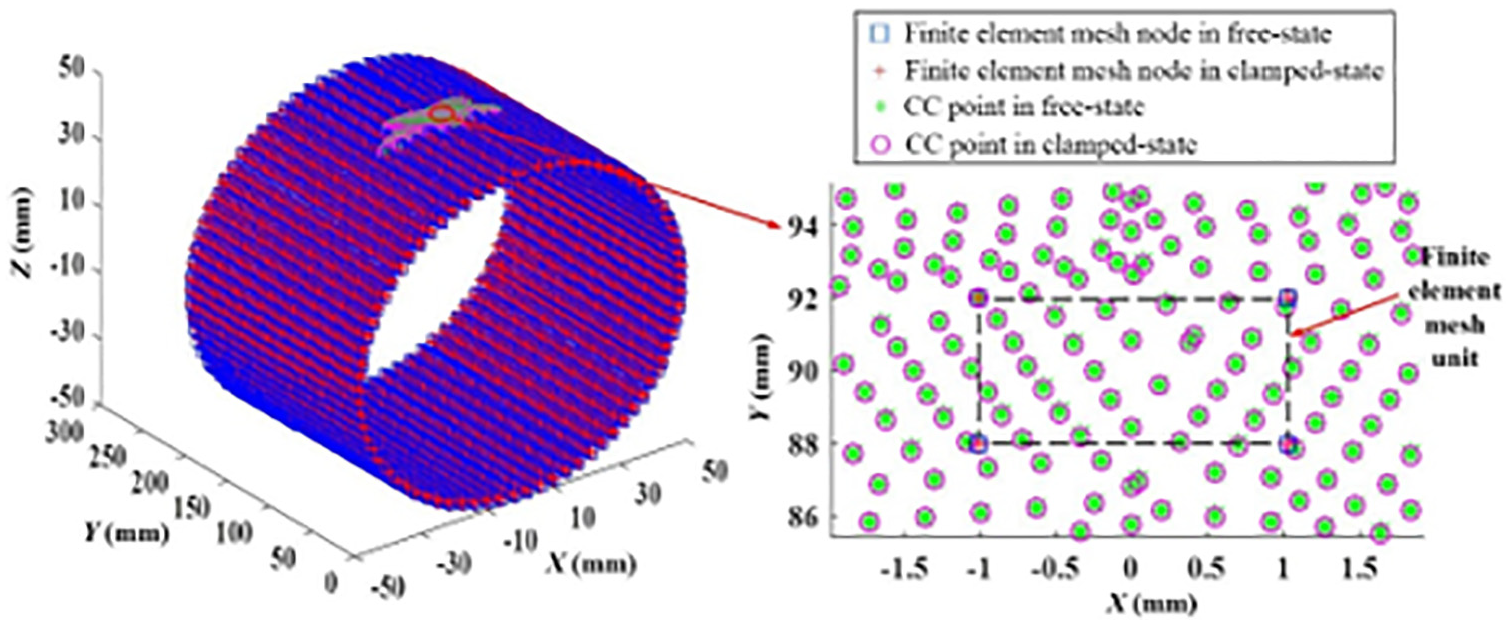
Calculation results of CC points under clamped-state by grid mapping.
According to equation (31), the unit normal vector
Results discussion
A comparison experiment is made between the mapped machining-path and the unprocessed machining-path for machining the thin-walled cylinder parts. The core of experiment is just to validate the method of machining-path mapping from free-state to clamped-state for thin-walled parts, and the processing parameters are suitable for aluminum alloy, so the validity of this method can be proved from the perspective of verifying the effectiveness of the machining-path mapping method. The final processing results are shown in Figure 11. It can be obvious found that the owing cuts happens for the clamping deformation by using the unprocessed machining-path. The machining depth for the graphic pattern can directly reflect the effect of the proposed mapping relationship for machining-path, and then the three coordinate measuring machine (CMM) is used to measure the variation of Z value for the machining depth as the judgment standard of machining quality.
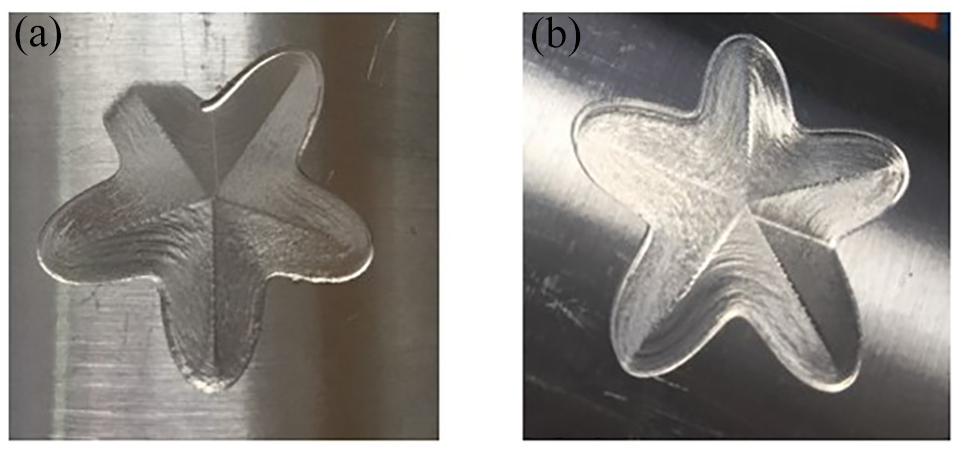
Machining result with unprocessed machining-path and mapped machining-path: (a) unprocessed machining-path and (b) mapped machining-path.
After measuring the variation of Z value for the machining depth of graphic pattern, the experimental result shows that the machining depth of graphic pattern on the outer surface of the thin-walled cylinder parts remains almost invariable with the re-designed machining-path, as shown in Figure 12(a). However, the machining depth of graphic pattern changes obviously with the machining-path obtained from design model, as shown in Figure 12(b). As shown in Section 4.2, the cutting depth is set as 0.3 mm in machining process. From the measuring results of Figure 12(a), the mean cutting depth is 0.2648 mm which is closer with 0.3 mm. Furthermore, the machining depth variation with the re-designed machining-path of thin-walled parts under clamped-state, just after the machining-path mapping, is 69.7 μm, and the standard deviation of measured data is 0.0189. While from Figure 12(b), the mean cutting depth is 0.1655 mm, just a little more than half of 0.3 mm as the clamping deformation. The machining depth variation for the machining-path obtained from design model is 296.4 μm and the standard deviation of measured data is 0.0786, which means the machining depth changes bigger and the processing quality is poor. In this way, it can be obvious found that the mean cutting depth is even closer the set cutting depth, and the machining depth variation and its standard deviation decrease by 76.5% and 75.9% respectively comparing with the machining result for the machining-path obtained from design model, when the re-designed machining-path of thin-walled parts under clamped-state is used. In a word, the machining depth change is smaller and the machining quality is obviously improved, which proved that the proposed method can achieve the avoiding purpose for the machining error caused by clamping deformation.
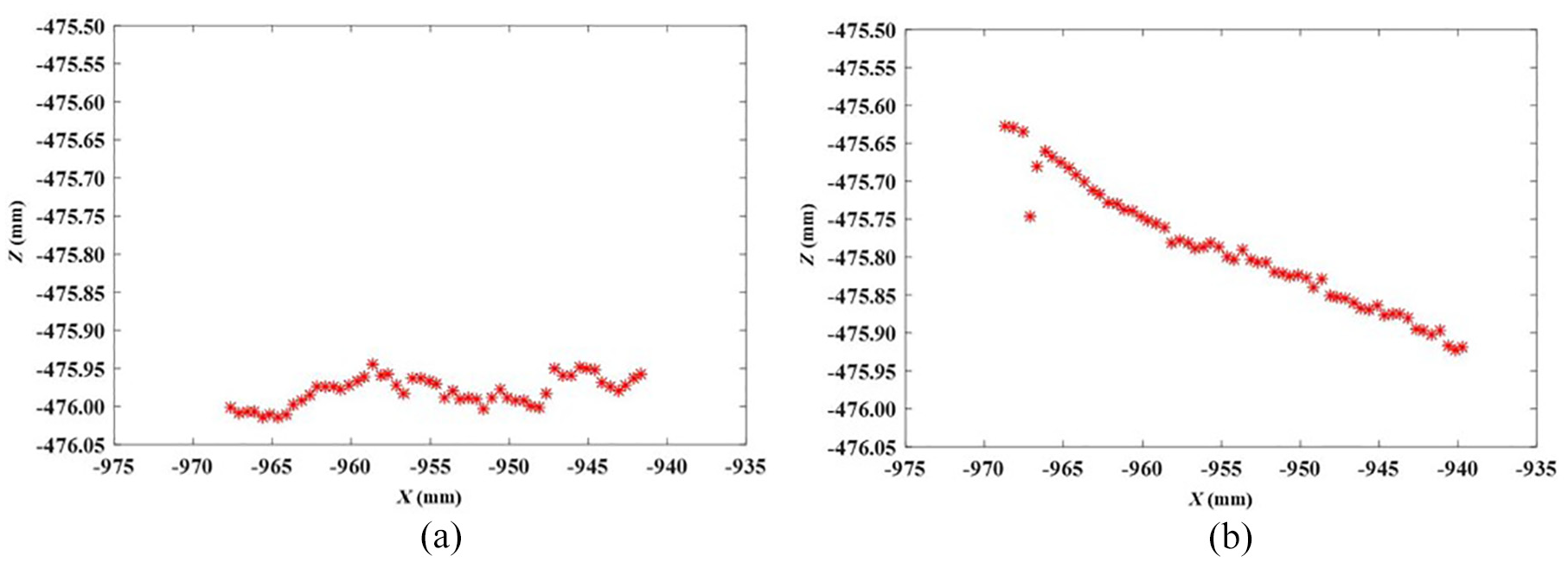
Machining depth variation with mapped machining-path and unprocessed machining-path: (a) mapped machining-path and (b) unprocessed machining-path.
Conclusions
As the clamping deformation is unavoidable for thin-walled parts with curved surface and by using the machining-path obtained from the design model, the machining accuracy requirement may easily not be met due to the springback of clamping deformation when the machining process is finished. In this study, the purpose of avoiding machining error caused by the springback of clamping deformation is achieved by machining-path mapping for thin-walled parts from the free-state to the clamped-state. According to the geometrical characteristics of the thin-walled parts with curved surface and taking into account the clamping layout, the corresponding relationship between CC point in free-state and that in clamped-state is established by grid mapping, and finally the machining-path for the thin-walled parts with curved surface is re-designed under the clamped-state based on the interpolation information between adjacent CC points under the free-state. The experiment results show that the mean cutting depth is even closer the set cutting depth, and the machining depth variation and its standard deviation decrease by 76.5% and 75.9% respectively comparing with the machining result for machining-path obtained from the design model, when the re-designed machining-path is used. In this way, the proposed method can improve the machining quality of thin-walled parts with curved surface, and has good applicability that can be extended to any kind of thin-walled parts in engineering applications. These research achievements are of vital importance for realizing high-quality machining for the thin-walled parts with curved surface.
Footnotes
Acknowledgements
The authors wish to thank the anonymous reviewers for their comments which led to improvements of this paper.
Declaration of conflicting interests
The author(s) declared no potential conflicts of interest with respect to the research, authorship, and/or publication of this article.
Funding
The author(s) disclosed receipt of the following financial support for the research, authorship, and/or publication of this article: The project is supported by NKRDPC (No. 2018YFA0704603), National Natural Science Foundation of China (No. 51975098 and U1937602), LiaoNing Revitalization Talents Program (No. XLYC1907006 and XLYCYSZX1901), Science and Technology Innovation Fund of Dalian (No. 2019CT01) and the Fundamental Research Funds for the Central Universities.