
Abstract
This work explores the effect of T6 heat-treatment on the microstructure, mechanical properties and dry sliding linear reciprocating wear behaviour of Al-7Si/Titanium Nitride (TiN) centrifugally cast functionally graded composite. The 10 wt% TiN particle addition and subsequent eutectic Si spheroidisation due to heat treatment revealed an improvement in microhardness, tensile strength and wear resistance of heat-treated composite when compared to as-cast composite. Reciprocating wear analysis at varying applied loads and sliding distances revealed a combination of specimen micro-ploughing and abrasive particle action at low load and sliding distances, which was in stark contrast to the combination of abrasive and adhesive wear at higher loads and sliding distances. The surface was characterised by mechanically mixed layer formation due to tribo-oxidation, adhesive and delamination wear mechanisms. This composite can be utilised to replace traditional materials employed in reciprocating pump and compressor applications.
Keywords
Introduction
In the production of commercial products for customers, the aerospace and automotive sectors use alloys from the Al-Si system as they are a good option for fabricating complicated, thin-walled components using sand or permanent mould castings. These alloys are used in a variety of automotive and aerospace components due to their good castability and fluidity properties, as well as a combination of high ductility, high specific strength, high corrosion and wear resistance.1–3 A356 (Al-7Si), a hypo-eutectic alloy from the Al-Si-Mg system, is used widely in recent decades for vehicular-engine block/head applications due to its excellent casting ability, high strength/weight ratio and excellent heat-treatable characteristics.4,5 Cooling rate, modification and heat treatment are the three factors that influence the silicon morphology. These factors influence the morphology change separately or in conjunction with each other to develop desired and optimum properties. Several researchers have reported an increase in tensile and yield strength in heat-treated Al-7Si-Mg gravity cast alloys, through the addition of magnesium. Mutual correlations exist between the solidification conditions, alloy compositions and heat treatment parameters.3,6,7 Heat treatment studies performed on Al-Si-Cu and Al-Si-Mg alloys revealed a better age-hardening response for Al-Si-Mg alloy than for Al-Si-Cu alloy, which was confirmed through microhardness results and X-ray diffraction (XRD) analysis. 8
The wear resistance of the A356 aluminium composites is improved by the addition of ceramic reinforcement particles such as silicon carbide (SiC) and alumina (Al2O3). 9 TiN displayed exceptional hardness, good electrical and optical properties, and when employed as a coating over other substrates, behaved as a hard surface and protected cutting and sliding surfaces. 10 Mechanical and dry sliding wear studies performed on Al-TiN (10, 30 wt%) composites fabricated via powder metallurgy route revealed an improvement in mechanical and wear resistance properties, due to the presence of TiN particles along the grain boundaries, which improved the densification in the composite. 11 Zhou et al. reported an improvement in the strength and ductility properties of Ni coated nano-sized TiN reinforced Al-Cu composite. This was mainly due to the refined grain microstructure developed through T6 heat treatment. 12 Metallography analysis performed at varying centrifugal speeds (1500, 2000 rpm) on centrifugally cast Al-SiC functionally graded composites (FGCs) revealed a sharp gradient distribution in reinforcement particles at higher speeds, whereas a smooth gradient distribution was observed at lower speeds. 13
The mechanical and tribological study conducted on SiC/AA7075 FGC fabricated through centrifugal casting revealed that the wear rate increased with increasing sliding speed, applied load and sliding distance. It was also observed that abrasive, adhesive, delamination and tribo-oxidation were the prominent wear mechanisms influencing wear at high load and speed conditions. 14 Fretting wear studies performed under varying applied loads and fretting cycles on A356-SiC composite under as-cast and heat-treated conditions revealed that T6 treatment had improved the composite wear resistance. The volume of wear generated had also increased with increasing applied load. 15 A reciprocating wear study on squeeze cast B4Cp (15, 19 vol.%)/Al-9Si-3Cu-Mg was performed by varying parameters such as volume fraction of reinforcement particles, applied load and sliding distance. It was concluded that volume fraction and applied load had the highest influence on the coefficient of friction (COF) and wear rate, with the wear mechanism observed comprising a combination of different wear mechanisms such as abrasive, adhesive and delamination. 16
From the literature study, it was concluded that most studies had focussed on metal matrix composites synthesised using alloys from the Al-Si-Mg and Al-Si-Cu system and limited reports were available on SiC, Al2O3, B4C, TiC reinforced FGCs, wherein the focus was on their dry sliding wear response. However, very limited papers were available on the heat treatment study of FGCs reinforced with TiN particles and the corresponding reciprocating wear behaviour. Given these facts, the current study focuses on the functionally graded concept in Al-7Si (A356) alloy reinforced with TiN. The composite containing 10 wt% particles was synthesised through the centrifugal casting method and was subsequently heat-treated. The microstructure and mechanical property studies were performed across the cross-section for as-cast and heat-treated composites. The reciprocating wear behaviour was analysed at varying applied loads (10–50 N) and sliding distances (500–2500 m) and was compared against the as-cast composite.
Materials and experimental methods
Material selection
Aluminium A356 (Al-7Si) alloy was selected as the base metal matrix for fabricating the FGC. The existing material properties such as tensile strength, hardness and ductility can be improved to a certain extent through the thermal treatment of aluminium alloy. 17 TiN was preferred as the reinforcement material in the aluminium alloy matrix and to avoid cluster behaviour in the melt, an optimum concentration of 10 wt% was selected. 18 Figure 1 displays the scanning electron microscope (SEM) image of as-received TiN reinforcement particles having an average particle size of 20 ± 10 µm. The matrix and reinforcing materials were supplied by M/s Coimbatore Metal Mart, India. The spectroscopic chemical composition of the as-received alloy is shown in Table 1.
A356 alloy ingot spectroscopic chemical composition.
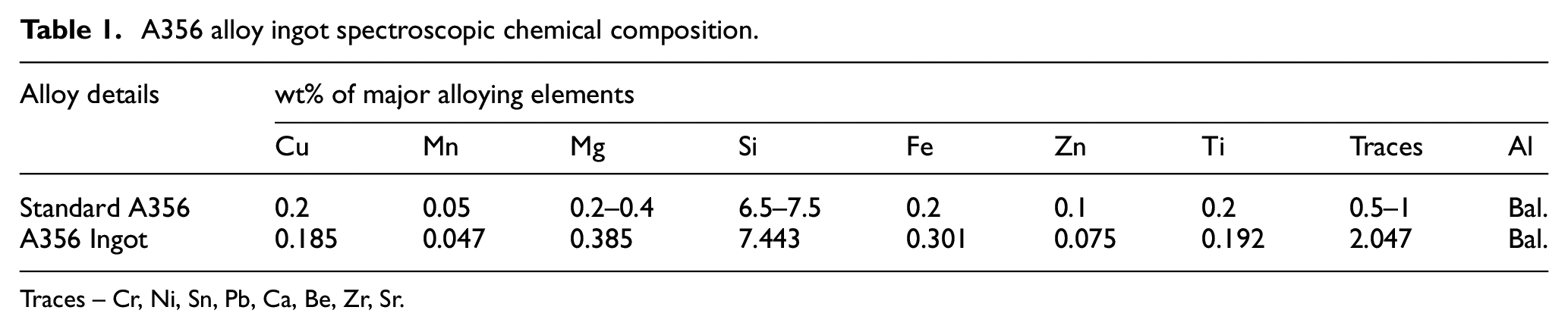
Traces – Cr, Ni, Sn, Pb, Ca, Be, Zr, Sr.
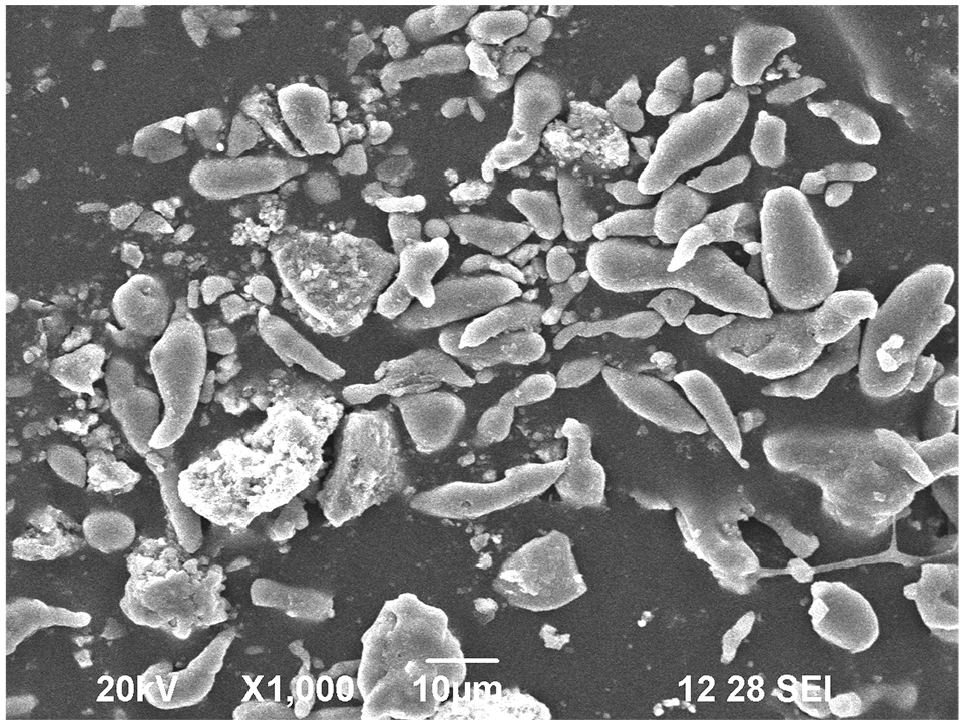
SEM image of as-received TiN particles.
Fabrication process
The fabrication process involves a two-step method wherein the ingot pieces were initially melted through a liquid metallurgy route (indigenous two-step) followed by horizontal centrifugal casting in which the molten metal was poured into a hollow cylindrical die Øout 100 × 100 mm to produce a hollow cylindrical specimen of dimension Øout 100 × Øin 50 × 100 mm. 19 The liquid metallurgy route involves melting alloy ingot pieces in a graphite crucible with a capacity of 10 kg placed inside an electric resistance furnace. The temperature was then slowly lowered below liquidus temperature to add the preheated reinforcements and magnesium ribbons (1 wt%) to the molten metal through a hopper while the first step mechanical stirring was performed. The addition of magnesium to the molten metal aided in creating a reaction barrier, thus controlling any adverse interfacial reactions formed.20,21 The second step of stirring was done after increasing the temperature to aid in the proper distribution of added ceramic particles in the semi-solid melt. Figure 2 illustrates the fabrication process followed for fabricating the composite. Table 2 shows the process parameters employed for the fabrication process.
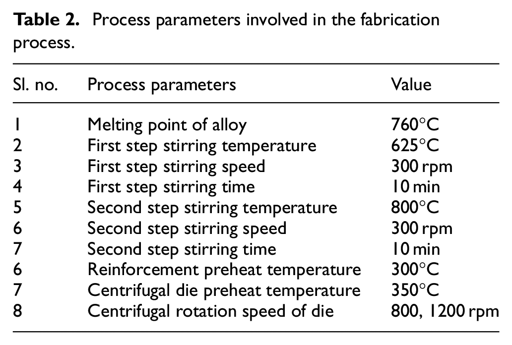
Process parameters involved in the fabrication process.
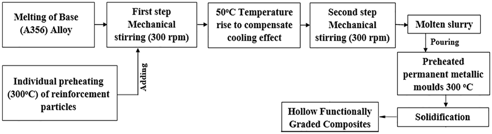
Schematic illustration of the fabrication process.
Selection of heat treatment parameters
Heat-treatment conditions (T6 temper) were chosen in line with the American Society for Testing and Materials (ASTM) T6 tempering standards. The as-cast FGC specimens were subjected to initial solutionizing at 560°C for 10 h, quenching the specimens in 60°C warm water followed by artificial ageing at 165°C for 6–12 h. These processes were carried out in an industrial furnace (M/s Technotherm Industries, India). After age treatment, the specimens were air-cooled to room temperature.
Density and porosity study
The density of the fabricated FGC was studied following Archimedes’ principle. Theoretical density was calculated following the ‘Rule of Mixtures’. The percentage of porosity level in the fabricated composite was calculated theoretically after obtaining actual and theoretical density values.
Microstructure, elemental mapping and XRD analysis
The specimen samples cut from the fabricated composite were prepared following the ASTM E3-11 standard for the metallography analysis. The microscopic features developed on the as-cast and heat-treated FGC outer and inner layers were studied using a ZEISS Field Emission Gun Scanning Electron Microscope (FE-SEM) equipped with Energy Dispersive Spectrometer (EDS). An XRD study was performed on as-cast and heat-treated composite to identify and verify the different elements present. A Philips X’Pert diffractometer was employed for this study.
Microhardness and tensile tests
Microhardness tests were conducted, following ASTM E384 standards, at five different locations on three specimens each of the inner, middle and outer layers of as-cast and heat-treated composites. The hardness values were measured using a Mitutoyo Vickers hardness tester equipped with a pyramid-shaped diamond indenter. A Tinius Olsen make computerised Universal Testing Machine was used to study the tensile behaviour of as-cast and heat-treated specimens prepared following the ASTM B557 standard. The test was repeated thrice for both as-cast and heat-treated composite. After the tensile test, the fractured side of the specimen was analysed for fractography study.
Linear reciprocating wear study
The linear reciprocating wear behaviour of as-cast and heat-treated composite specimens was studied by employing a DUCOM make pin on a flat reciprocating tribometer. Specimens of dimension 9.57Ø × 15 mm length were machined following ASTM G133 standards. An excellent high carbon alloy steel, EN 31 (hardness 266 HV and surface roughness 0.75 Ra) was employed as the counter plate, as it offered a high measure of hardness with compressive strength and abrasion resistance. Tribological parameters like applied load (10–50 N) and sliding distance (500–2500 m) were chosen based on the literature study conducted. 16 A constant frequency of 7 Hz was maintained for all the experiments. The following expression was used to calculate the specific wear rate.

where sliding distance = Stroke length x Time x Frequency mm
Results and discussion
Microstructure, elemental mapping and XRD results
Figure 3(a) and (b) represent FE-SEM micrographs of the as-cast outer and inner layers. The as-cast composite matrix displayed a gradient distribution of eutectic Si and TiN reinforcement particles alongside a large portion of α-Al phases. It was also observed that the outer layer (Figure 3(a)) had a higher concentration of eutectic Si and TiN reinforcement particles than the inner layer (Figure 3(b)). This was due to the centrifugal force action, which created a radial outward motion for the higher density reinforcement particles to move towards the outer layer, whereas low-density air bubbles generated during casting move towards the inner layer. This observation is in complete agreement with the results observed in previous studies reported in centrifugally cast FGCs.13,22,23 The eutectic Si particles were distributed throughout the aluminium matrix and had more accumulation near the grain boundaries. No porosities were observed in the outer layer, which concluded that the interfaces were continuous and defect-free with very good wettability. Magnesium added during casting aided in reactive layer formation around the reinforcement particles, thus enhancing wettability. 24 Figure 3(c) represents the elemental mapping results of the as-cast composite outer layer. The elements confirmed were Al (green), Si (red) whereas Ti and N were observed to be non-clustered within the aluminium matrix interface as represented by violet and blue respectively. A finite trace of Mg was also observed (yellow) due to the minor percentage of Mg added, in the form of ribbons, intentionally during casting to catalyse the reaction.
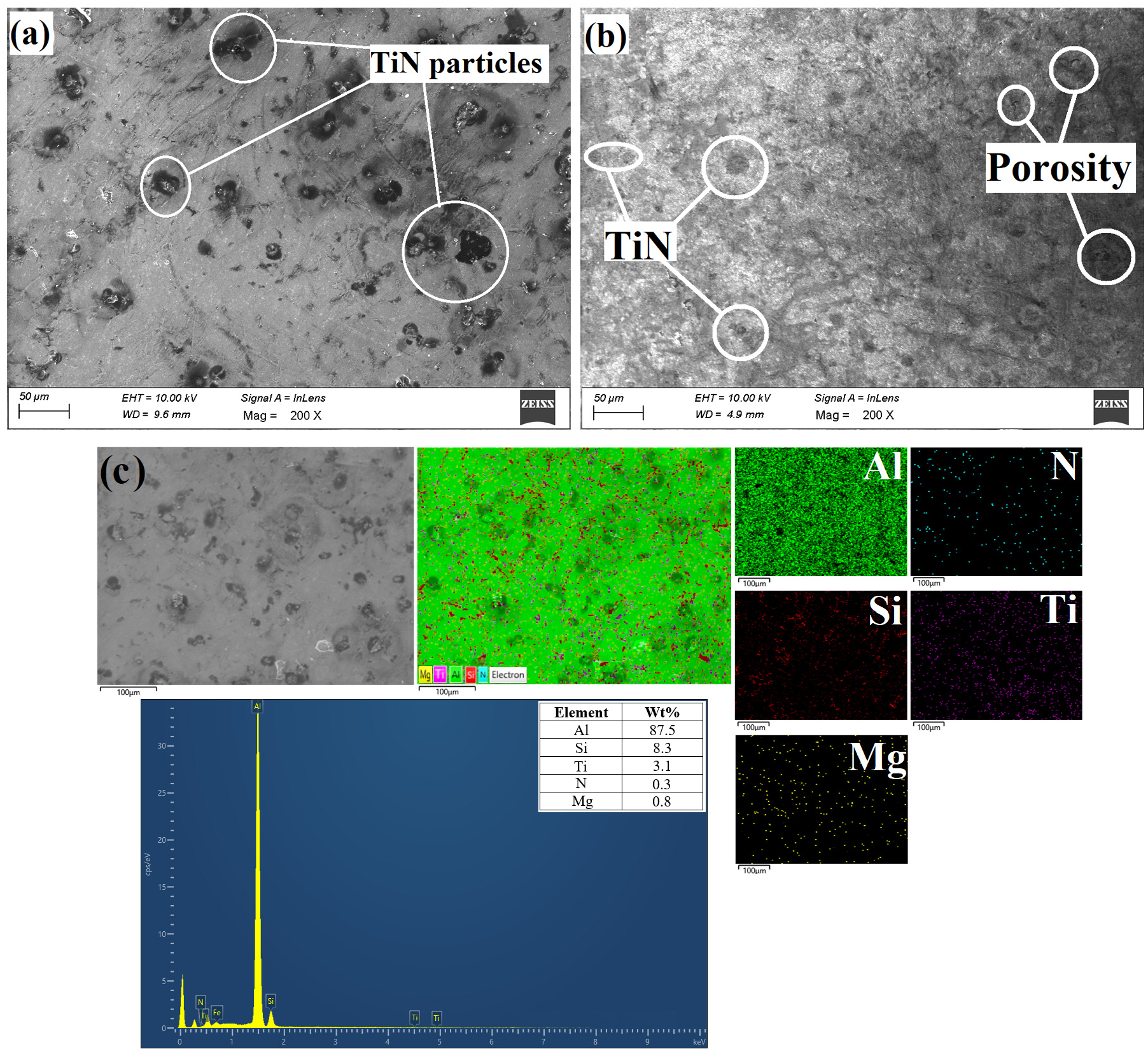
As-cast FGC: (a) FE-SEM micrograph of the outer layer, (b) FE-SEM micrograph of inner layer and (c) elemental mapping and EDS analysis result.
The as-cast composite matrix which displayed the presence of primary phase α-Al and a eutectic Al-Si mixture underwent grain refinement during heat treatment. Figure 4(a) and (b) represent the FE-SEM images of the heat-treated composite at the outer and inner layers respectively. The eutectic Si particles initially observed as elongated rods and irregular plates, had transformed into spheroidised silicon particles (Figure 4(a)), and were mainly located in the vicinity of reinforcement particles. 25 It was confirmed from previous literature that at solidus temperature lines, aluminium alloys that were heat treatable displayed good solid solubility characteristics. The cast specimens were solutionized at 560°C to prevent Mg phases from undergoing local melting, as any alloy with Mg content should be solutionized just above recrystallisation temperature. By solution-treating the cast specimen for 10 h, eutectic Si in the form of long rods and plates broke down into smaller fragments. Age treatment gradually transformed the coarse eutectic Si fragments to spheroidised Si. Meagre Mg2Si phase formations were also observed, as confirmed through XRD analysis. 6 Moving from the outer periphery to the inner core, coarse eutectic Si fragments were observed in the form of rods alongside spheroidised eutectic Si (Figure 4(b)). Figure 4(c) shows the elemental mapping results of the heat-treated composite outer layer, wherein the elements observed were mainly Al (red), spheroidised eutectic Si (green), Ti (purple) and N (blue). Minute traces of Mg phases were also observed as confirmed through the mapping results.
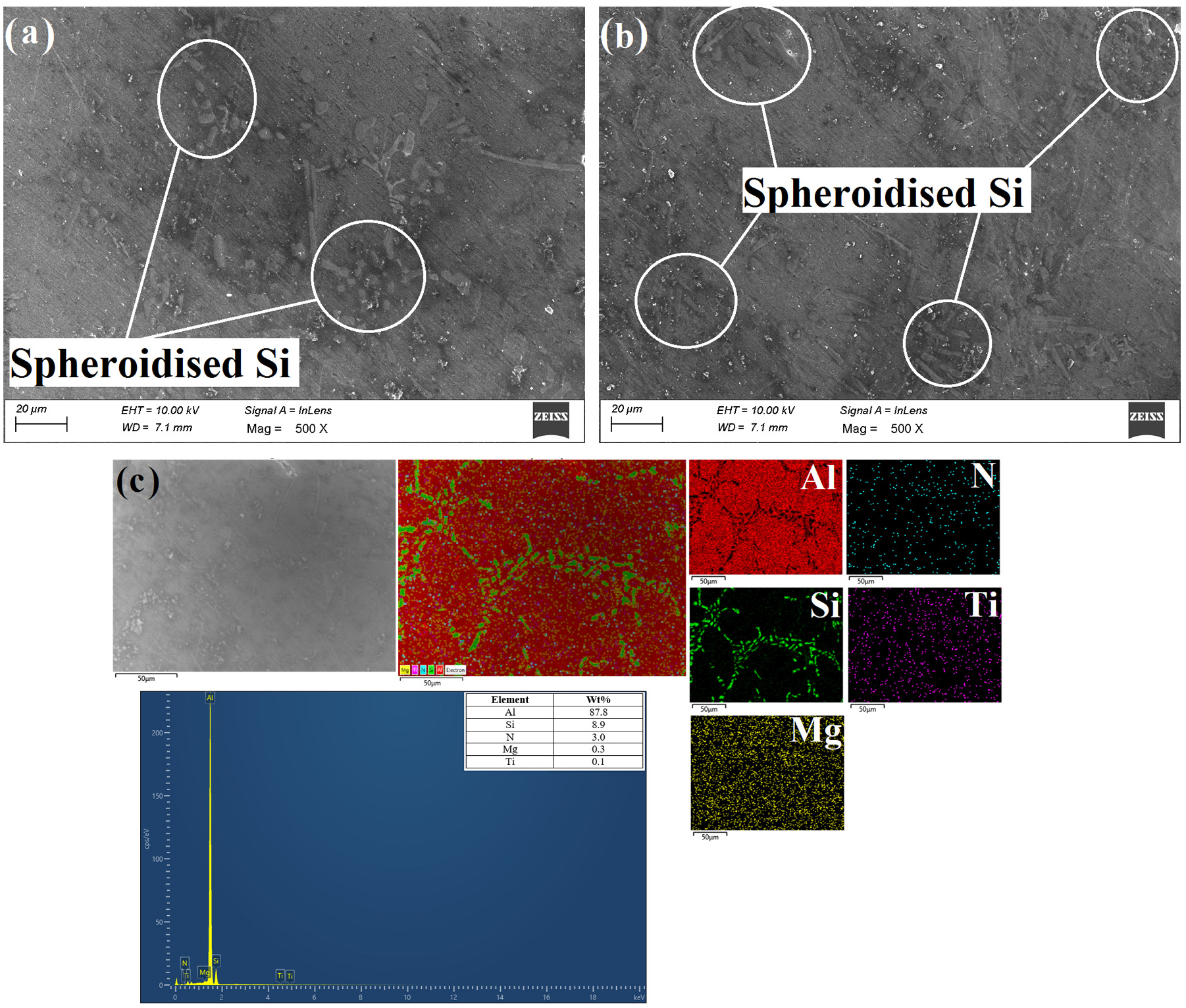
FE-SEM micrographs of heat-treated FGC: (a) outer layer, (b) inner layer and (c) elemental mapping and EDS analysis result.
Figure 5 depicts the XRD analysis results of the outer zones of as-cast and heat-treated FGC. In analysing the XRD results of the as-cast composite (Figure 5(a)) and the heat-treated composite (Figure 5(b)), the intensity peaks observed had confirmed the presence of aluminium, silicon and magnesium. Peaks observed at 2θ = 37.03°, 43.72°, 47.82°, 54.78°, 61.27° and 75.32° in Figure 5(a) and peaks observed at 2θ = 39.61°, 42.17°, 42.77°, 43.12° and 74.59° in Figure 5(b) confirm the successful incorporation of TiN particles, as corroborated by JCPDS card number 38–1420. 11 The diffraction peak corresponding to TiN (111) at 30° had reduced significantly owing to the increase in the angle and had subsequently vanished. Upon comparing both graphs, it was concluded that a left-side shift in peaks had occurred for the heat-treated composite, which confirmed the elimination of any defects present and the relaxation of any built-up stresses in the composite.
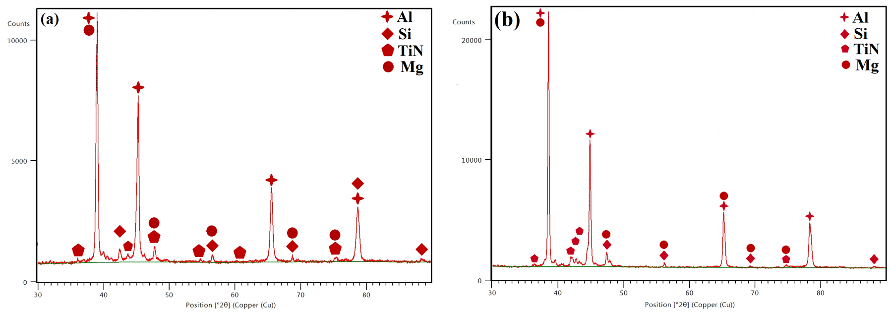
XRD results of: (a) as-cast and (b) heat-treated FGC.
Density and porosity results
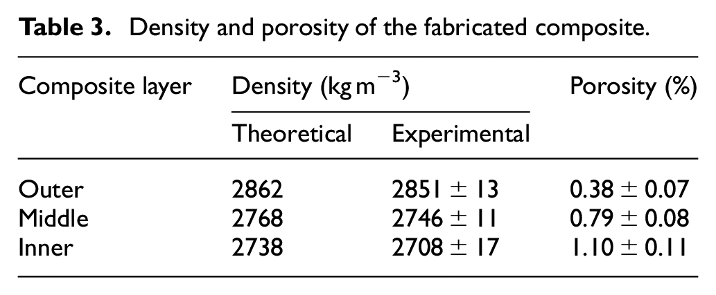
Table 3 shows the porosity, theoretical and density values for three different layers of the fabricated composite. The results observed for the fabricated composite were contrary to the expectation of increasing density, due to the high density of reinforcement particles that is, TiN (ρ = 5400 kg m−3) when compared to the density of the matrix that is, aluminium (ρ = 2700 kg m−3). Comparative analysis revealed higher density and minimal porosity values for the outer layer than the inner layer, due to the increasing high-density reinforcement particle concentration from the inner to the outer periphery. This was caused by the high-density reinforcement particle motion towards the outer periphery owing to the high centrifugal rotation motion. 26 The inner layer shows minimum density values due to minimal concentration of reinforcement particles, as confirmed through microstructural study.
Density and porosity of the fabricated composite.
Microhardness, tensile and reciprocating wear results
Figure 6(a) depicts the results of the microhardness study performed on specimens cut from casts fabricated at centrifugal speeds of 800 and 1200 rpm to study the effect of centrifugal die rotation speed on the material properties. The microhardness values observed had increased with increasing centrifugal rotation speed, which can be attributed to the increased reinforcement particle concentration towards the outer periphery. Comparative analysis revealed that the specimen cast at 800 rpm showed a noticeable difference in hardness values for all three layers when compared to the specimen cast at 1200 rpm. Therefore, a better gradient distribution of reinforcement particles was obtained at 1200 rpm rotational speed than at 800 rpm rotational speed.12,27
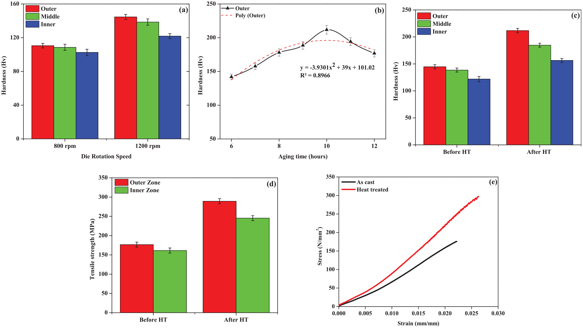
(a) Microhardness as a function of die rotation speed, (b) microhardness as a function of ageing time, (c) microhardness before and after heat-treatment, (d) tensile strength before and after heat-treatment and (e) true stress versus true strain plot.
To find the optimum ageing time at which the maximum hardness values were observed, specimens were age treated for varying ageing time durations that is, 6–12 h at a constant interval of 1 h. Figure 6(b) concluded that the completely-spheroidised eutectic Si particles in the 10-h age treated specimen had enhanced the specimen to show superior hardness values. The hardness values decreased after an ageing time of 10 h, mainly due to the over-ageing phenomenon wherein the Si particles underwent a grain coarsening effect. 28
Figure 6(c) depicts the microhardness results of as-cast and heat-treated FGC inner, middle and outer layers, which revealed an improvement of nearly 27%, 33% and 46% for the inner, middle and outer layers of the heat-treated composite when compared to the respective layers of the as-cast composite. Figure 6(d) depicts the tensile test results of the inner and outer zone specimens of as-cast and heat-treated composites, whereby the heat-treated composite specimens revealed superior ultimate tensile strength than their as-cast counterparts by 63.7% and 52% respectively. All layers of heat-treated composites displayed enhanced microhardness and tensile strength values than their corresponding as-cast counterparts, which confirmed that the T6 age-treatment had improved the material properties through grain refinement.
The as-cast composite outer layers displayed superior hardness and tensile strength values due to the high concentration of TiN particles, eutectic Si particle spheroidisation and the formation of Mg2Si phases and any Al-Ti intermetallic phases. This generated a critical radius in the matrix, leading to the formation of fine spheroidised structure, which imparted additional surface hardness to the heat-treated composite. 5 Under normal cooling conditions, the eutectic Si particles which had existed in the aluminium matrix as coarse acicular needles, acted as crack nucleation sites and decreased the material properties. Under solutionising and subsequent ageing process, these particles broke down into finer particles and gradually underwent spheroidisation, which enhanced the material properties of heat-treated specimens. It was already known that the thermal expansion coefficient mismatch generated between the reinforcement particles and the aluminium matrix contributed to the high hardness and tensile strength values. 29 Due to the incorporated reinforcement particles, the surface area is enhanced and the aluminium matrix grain size is subsequently reduced, which decreases the matrix softness. The hardness and stiffness of the fabricated composite had improved due to the presence of hard reinforcement particles and offered high resistance to any plastic deformation. The generated thermal expansion mismatch caused an enormous build-up of internal stresses, which caused the plastic deformation of the aluminium matrix and allowed it to trap the smaller volume expansion of reinforcement particles. This dislocation density augmentation at the interface of reinforcement particles and aluminium matrix generated increased resistance to plastic deformation, thus producing enhanced hardness. 30
As radial distance increased towards the inner core, a simultaneous decrease in the hardness and tensile strength values were observed, and continued to reduce further towards the core (centre). This was mainly due to the decreasing concentration of TiN particles. Minimal amount of porosity, a strength inhibiting flaw, was also observed in the inner layers of the composite, and acted as crack nucleation sites. With increasing stress concentration, the nucleated cracks at these zones propagated, which decreased the strength of the composite. Hence, the decrease in hardness and tensile strength at the inner layer was concluded to be due to the presence of air bubbles, which increase the porosity concentration at these layers. 14 Figure 6(e) illustrates the true stress versus true strain plots for as-cast and heat-treated composite outer zones.
The fracture surfaces observed for both as-cast and heat composite outer zones were oriented perpendicularly to the tensile axis. Also, the presence of high reinforcement particle concentration and alloying elements in the matrix alongside coarse Si percentage aided in brittle fracture of the specimen. Figure 7(a) depicts the as-cast FGC fracture surface, wherein the surface was composed mainly of coarse dimples, bright, shiny cleavages and microcracks along with minimal plastic deformation at the edges (dull grey), which led to the conclusion that the specimen had experienced a mixed-mode (ductile-brittle) failure. 31 On close examination, it was confirmed that the fracture surface had microcracks and smooth planar facets in the coarse eutectic Si region, which were primary features of brittle mode of fracture and poor plastic deformation. Upon analysis, the heat-treated composite fracture surface (Figure 7(b)) was observed to have bright and shiny cleavages alongside planar facets in the eutectic Si range of the aluminium matrix. Due to spheroidisation of coarse acicular silicon, the microcracks which nucleated at the interface developed between Si platelets experienced resistance to crack propagation. Spheroidised eutectic Si suppressed the stress concentration in the matrix around the stress fields, which enhanced the minimal ductility property of the sample. The failure observed was trans-granular type and the fracture was mainly mixed-mode type (ductile-brittle). 32
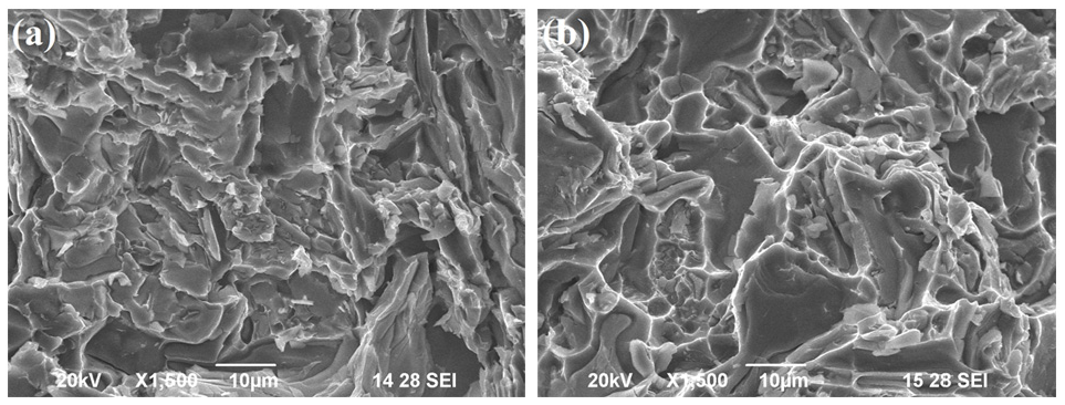
Fractographs of: (a) as-cast and (b) heat-treated outer zone.
The effect of applied load on the dry sliding linear reciprocating wear rate and COF of as-cast and heat-treated FGC was studied by maintaining a sliding distance and frequency of 1500 m and 7 Hz respectively. Figure 8(a) and (b) depict the effect of increasing applied load on wear rate and COF. Analysis of the results revealed superior wear resistance for the outer layers than the inner layers, due to the increased hard ceramic particle concentration in the aluminium matrix. Comparative trend analysis (Figure 8(a)) of the outer layers of the as-cast and heat-treated composite revealed superior wear resistance for the heat-treated composite compared to the as-cast composite, highlighting the effect of reinforcement particle addition as well as precipitation hardening and eutectic Si particle spheroidisation due to heat treatment. The transformation of the eutectic Si structure along with decomposition and fine refinement of the inhomogeneous dendritic structure of the matrix during the heat treatment process, aided in the improvement of the mechanical and tribological properties.
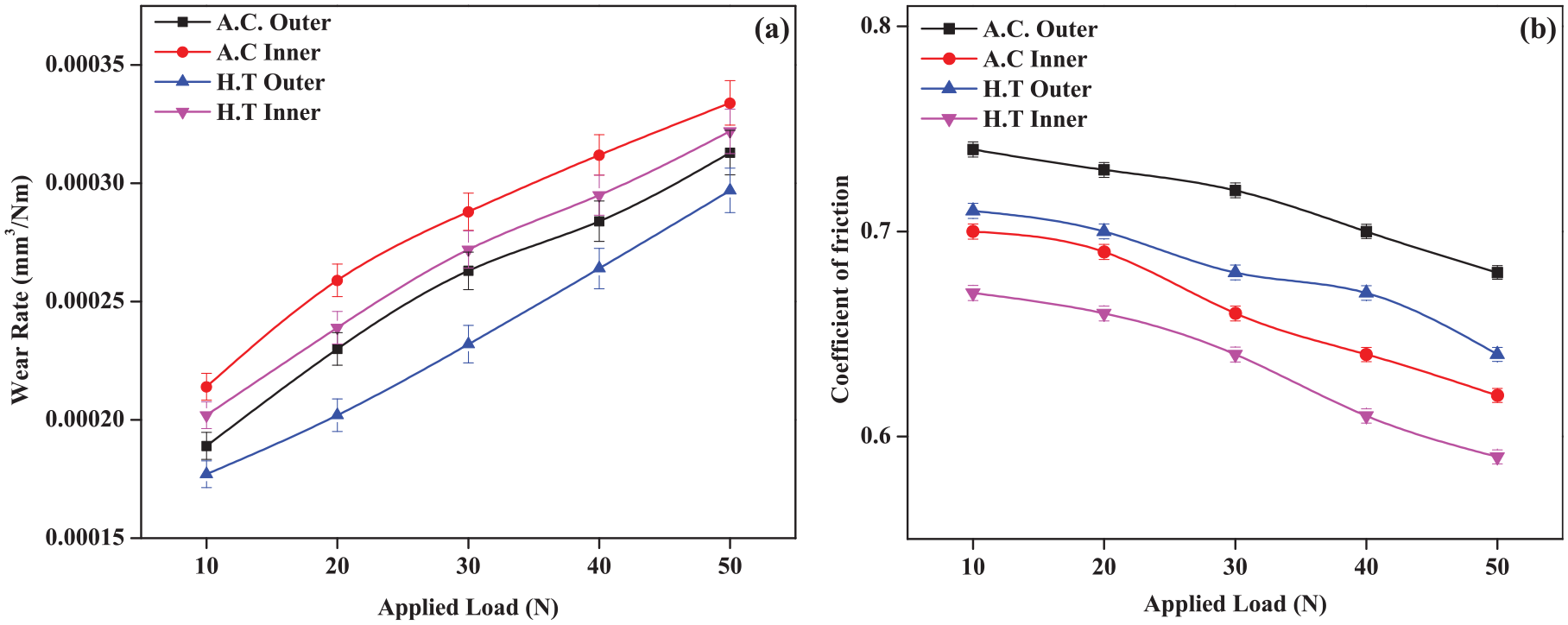
Plots showing the effect of applied load on: (a) wear rate and (b) COF.
The TiN particles behaved as load bearers at lower applied loads (10 N) as any stresses developed were less than the particle fracture threshold. The spheroidised eutectic silicon fragments acted as dislocation constraints against the deformation of the material for the heat-treated outer layer as compared to the as-cast outer layer. The composite inner layers behaved similarly to monolithic alloy and experienced crack nucleation and propagation at the Al/Si interfaces. However, at higher loads, that is, 50 N, all layers of the as-cast and heat-treated composites followed an increasing material removal rate, with severe surface and subsurface wear of specimens. Previous studies have revealed that the plastic deformation occurring at the interface between the specimen and the hardened steel counter plate had caused a temperature increase. The heat generated did not diffuse into the grit in the deformed material as the contact between the specimen and the counter plate was minimal. 33
Analysis of Figure 8(b) concluded COF to be inversely proportional to the wear rate, as it was dependent on the TiN particle concentration. 16 Due to the high concentration of reinforcement particles, both as-cast and heat-treated composite outer layers contributed to higher COF values at low load, whereas the COF values decreased with increasing applied load. The outer layer of the heat-treated composite had displayed lower friction values than that of the as-cast composite, due to the increase in the contact area between the specimen and the counter plate, which subsequently increased the contact temperature, thus leading to specimen softening. This resulted in slipping action between the contact surfaces, which reduced the COF values. An increase in temperature had occurred with increasing load, due to an increase in the nominal area of contact between pin and counter plate. This caused material softening at the interface, thus increasing the rate of slipping action between the contact surfaces and thereby reducing the COF.34,35
From the mechanical tests and wear experiments performed on the as-cast and heat-treated composites, it was concluded that the latter exhibited superior wear resistance, hence wear morphology analysis was performed only on the outer layer of heat-treated composite. Figure 9(a) to (e) show the FE-SEM images of heat-treated composite outer layer specimens at an applied load of 10, 20, 30, 40, and 50 N respectively.
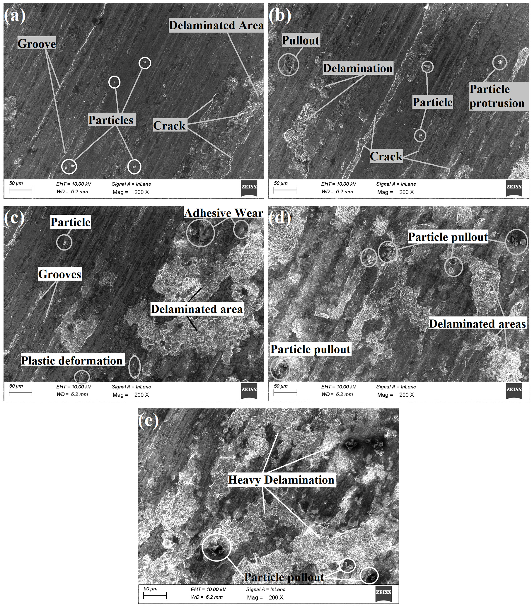
Heat-treated composite outer layer worn surface morphologies at: (a) 10 N, (b) 20 N, (c) 30 N, (d) 40 N and (e) 50 N.
At lower loads, that is, 10 and 20 N (Figure 9(a) and (b)), the worn surface analysis revealed predominantly long, continuous grooves as a result of micro-ploughing, a form of mild abrasive wear. With increasing applied load, more and more reinforcement particles were observed on the specimen surface as protrusions, which behaved as load carriers until they broke down into smaller fragments and assisted in increased micro-ploughing. As the load increased to 30 and 40 N (Figure 9(c) and (d)), the wear mechanism slowly transitioned from mild abrasion to severe abrasion and adhesion wear, with the matrix material undergoing thermal softening and plastic deformation due to surface fatigue. An increasing number of abrasive particles were pulled out, which accelerated the rate of abrasive particle action on the specimen surface. This increased the rate of volume loss, due to ploughing caused by repeated secondary particle action and micro fatigue caused by low cycle fatigue. At high load, that is, 50 N, micro fatigue and microcracking increased the rate of delamination formed on the specimen surface (Figure 9(e)). Microcracking and surface fatigue were the dominant wear sub-mechanisms influencing the wear, owing to crack formation and propagation that developed on the brittle composite surface.
The specimen surface observed at high load, that is, 50 N, was analysed through line mapping and the results are shown in Figure 10(a) to (c). Figure 10(a) shows the specimen area of the outer layer of heat-treated FGC where line mapping was performed. Figure 10(b) depicts the obtained EDS spectra and Figure 10(c) displays the line EDS mapping plots. The results confirm the specimen surface to be composed mainly of Fe and O alongside Al and Si. This established the formation of oxide layers on the surface of the specimen alongside ferritic oxides which controlled the COF. Figure 10(c) confirms the presence of magnesium (green line) alongside titanium (pink line) and nitrogen (blue line).
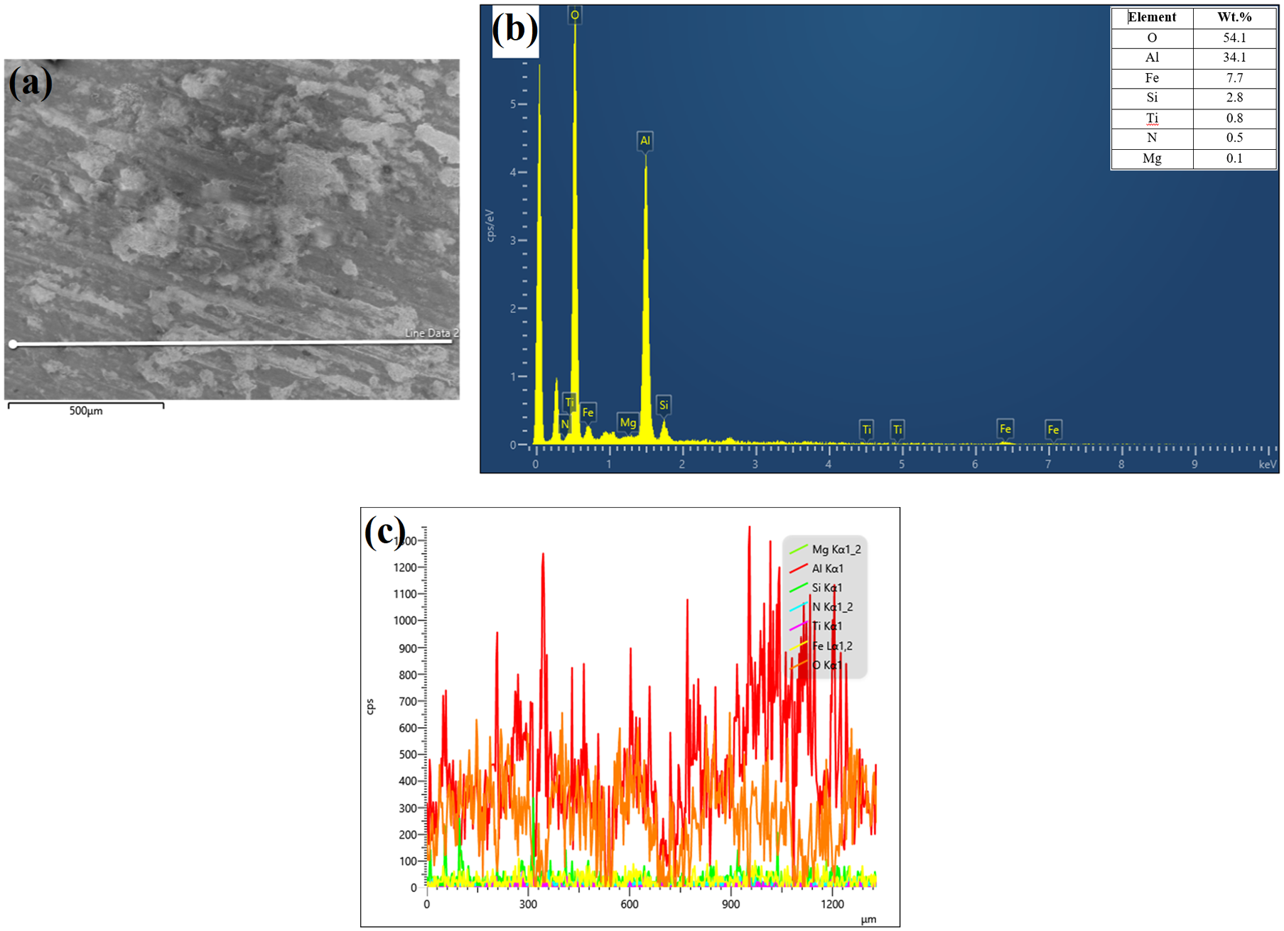
(a) SEM image of the specimen showing line mapping area, (b) EDS of specimen at 50 N and (c) line graph EDS of specimen at 50 N.
The effect of sliding distance on the dry sliding linear reciprocating wear and COF of as-cast and heat-treated FGC was conducted by maintaining the applied load and frequency at 30 N and 7 Hz for all experiments. Figure 11(a) and (b) show how wear rate and COF behaved under increasing sliding distance. Upon analysing Figure 11(a), it was concluded that all layers had initially shown an increasing wear rate trend up to a sliding distance of 2000 m. Beyond 2000 m, the wear rate suddenly decreased for as-cast and heat-treated composite outer layers, whereas the wear rate had approached a steady-state for inner layers. As-cast and heat-treated composite outer layers showed minimal wear as compared to the inner layers due to the high concentration of reinforcement particles and spheroidised eutectic Si particles present in the aluminium matrix. 36
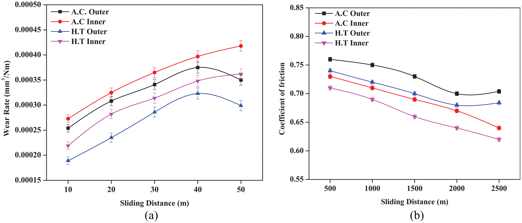
Plots showing the effect of sliding distance on: (a) wear rate and (b) COF.
At a low sliding distance, that is, 500 m, the heat-treated composite outer layer displayed a minimal material removal rate than the as-cast composite outer layer. This was due to the improved hardness and a refined grain structure that resisted deformation by constraining the dislocation motion generated in the matrix. As the sliding distance increased to 2000 m, the specimen surface underwent plastic deformation due to thermal softening and increased pin-counter plate interactions under contact/self-mated conditions. 37 Beyond 2000 m, the reinforcement particles which were either pulled out from the matrix or fragmented due to contact stresses began accumulating between the specimen pin and counter plate to form an abrasive medium. When the reinforcement particles abrade the hardened steel counter plate, the removed iron particles from the counter plate get oxidised to form iron oxides. These oxides mix together with fragmented reinforcement particles and aluminium oxides from the pin to form a lubricating layer called Mechanically Mixed Layer (MML). This layer, formed at the interface between the specimen pin and the counter plate, behaved as a lubricating layer between the mating surfaces and decreased the wear rate. 38
An analysis of the COF trends (Figure 11(b)) revealed high values initially for all layers, before showing a decreasing trend up to 2000 m. Beyond 2000 m, the frictional co-efficient values increased slightly, corresponding to the decreasing wear rate. This was mainly due to the hard second phase particles, which detached from the MML and behaved as constraints against the direction of sliding, thus increasing the COF.
Worn surface analysis was performed only for heat-treated composite outer layers as they exhibited minimal wear than other layers at longer sliding distances. Figure 12(a) to (e) shows the FE-SEM images of heat-treated composite outer layer specimens at varying sliding distances of 500, 1000, 1500, 2000 and 2500 m respectively.
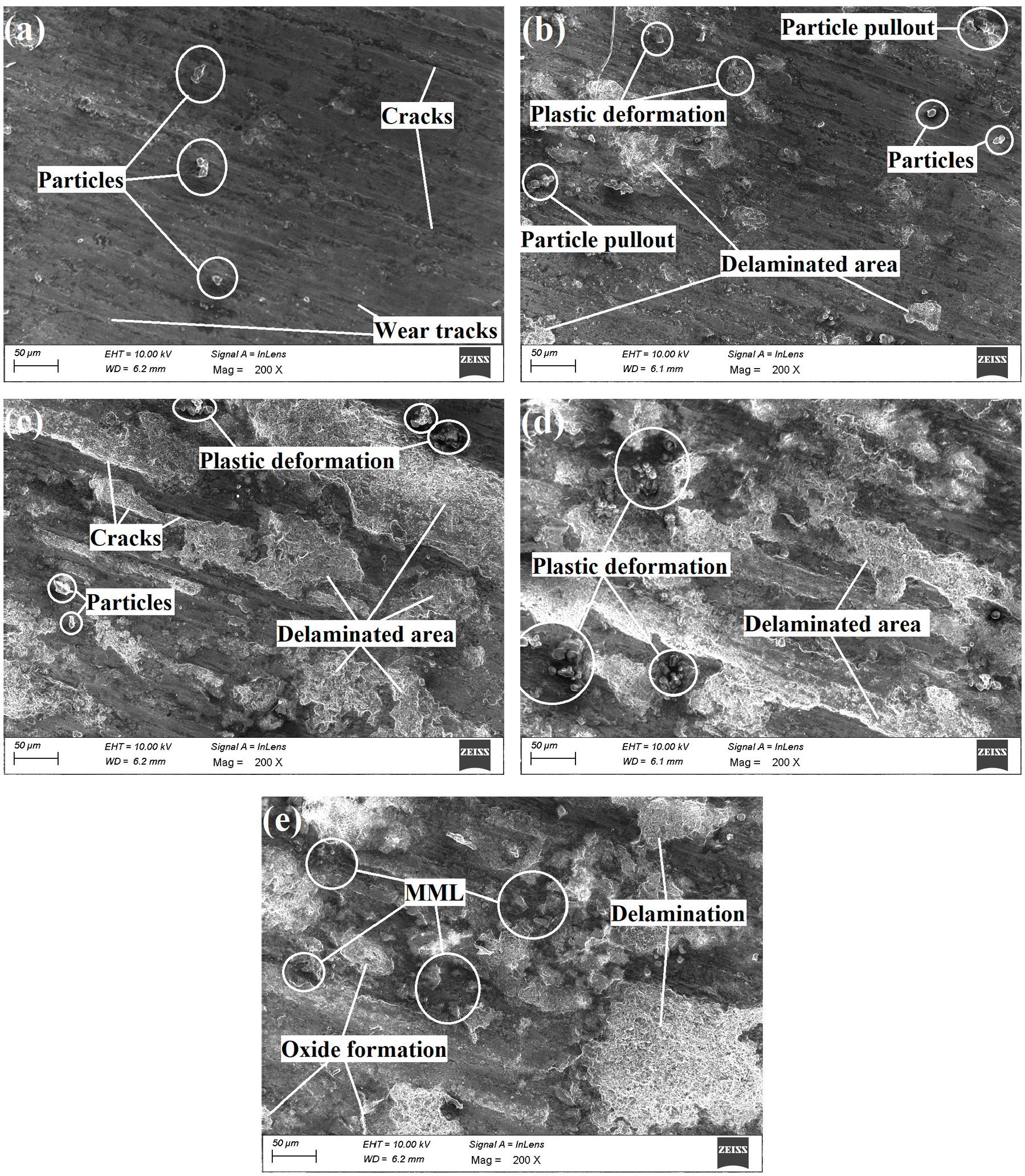
Worn surfaces of the heat-treated composite outer layer at: (a) 500 m, (b) 1000 m, (c) 1500 m, (d) 2000 m and(e) 2500 m.
The worn surface at 500, 1000 and 1500 m showed the presence of fragmented particles and particle pull-outs alongside wide wear tracks. The specimen surfaces displayed mainly cracks and cavities that were formed due to delamination and material tear. Comparative analysis of worn morphologies at 1000 m (Figure 12(b)) and 1500 m (Figure 12(c)) revealed a slow wear mechanism transition from the abrasive to adhesive mode of wear, with the material slowly adhering to the specimen surface. At 2000 m (Figure 12(d)), the surface underwent severe plastic deformation and the sub-mechanism influencing wear was mainly surface fatigue. At 2500 m (Figure 12(e)), the specimen surface depicted delamination mode of wear with oxides and loose debris contributing to MML formation. Wear sub-mechanisms such as tribo-oxidation and mechanical mixing predominantly define the wear at high sliding distances. With increasing sliding distance, the temperature increased as well, which led to increased chemical reactivity. This led to increased tribochemical reactions, which in turn caused oxide layer formation. 39 Some dark regions and patches were also observed on the specimen surface, which was analysed using EDS.
EDS analysis and elemental mapping were performed on the specimen surface at 2500 m as it showed the presence of MML. EDS analysis (Figure 13) revealed that the specimen surface had mainly Al, Si, Fe, Mg, Ti and N elements, which had a direct influence on the wear rate at higher sliding distances. The oxides of aluminium and titanium, along with oxides of iron, played an important role in resisting the deformation and decreasing the material removal rate of the heat-treated composite. 13 Elemental maps confirmed that the main elements present in the specimen surface at 2500 m were mainly Al (red image) and O (orange image), followed by Si (dark green image) and Fe (yellow image). Mg (neon green image), which was added to catalyse the reaction, was also present on the specimen surface alongside Ti (violet image) and N (blue image), which were observed to be non-clustered within the interfaces.
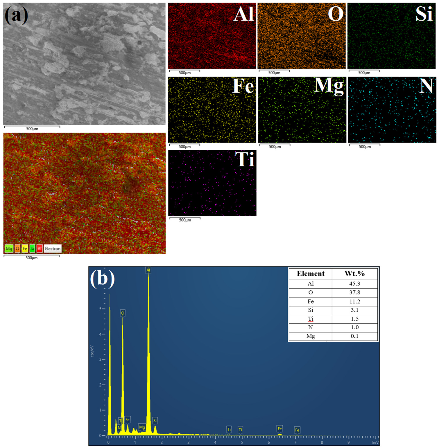
(a) Elemental mapping and (b) EDS spectra of specimen surface at 2500 m.
Conclusions
The functionally graded Al-7Si/10 wt% TiN composite was successfully processed through the liquid metallurgy route followed by horizontal centrifugal casting. The cast components and specimens were solutionized and age-treated in accordance with T6 tempering standards. Microstructure, mechanical and linear reciprocating wear studies were performed on both as-cast and heat-treated composite specimens. The results obtained from these tests are summarised as follows:
A gradient TiN reinforcement particle distribution was observed along the radial direction from the inner core to the outer crust of the as-cast composites, with the highest concentration of reinforcement particles observed at the outer region. Heat treatment successfully changed the morphology of acicular eutectic silicon to spheroidised silicon particles, which improved the microhardness and tensile strength of the composite.
Heat-treated composite outer layers displayed superior microhardness and tensile strength when compared to as-cast composite, mainly due to the hard TiN particles and modification in the microstructure due to T6 thermal treatment.
Linear reciprocating wear study confirmed that the heat-treated composite outer layer exhibited enhanced wear resistance. Wear analysis concluded that wear rate increases while COF decreases with increasing applied load. The outer layer wear rate increased with increasing sliding distance up to 2000 m, beyond which MML decreased the wear rate.
Analysis of wear morphology confirmed the presence of grooves, particle pull-outs, fragmented reinforcement particles, microcracks and delamination on the specimen surface. The specimen surface of heat-treated composite displayed oxide layer formation at higher sliding distances, suggesting tribochemical reaction wear mechanisms such as tribo-oxidation and MML formation.
Footnotes
Declaration of conflicting interests
The author(s) declared no potential conflicts of interest with respect to the research, authorship, and/or publication of this article.
Funding
The author(s) received no financial support for the research, authorship, and/or publication of this article.