
Abstract
In this research, thermoplastic polyimide (TPI) were welding via friction stir spot welding (FSSW) in order to evaluate the feasibility of the technology. The welding tool with a tri-flute pin was used for keeping the welding effectiveness. The effect of the rotation speed and dwell time on the microstructure and shear strength was studied. The results shows that the number of gap defects between the shoulder affect zone and the pin affect zone decreased with the increase of the rotation speed. The boundary of the shoulder affect zone and the pin affect zone was no clear when increasing the dwell time from 10 s to 20 s. Long dwell time could increase the mixing time and reduce the materials viscosity, which made the structure was denser. The maximal shear strength was obtained 85.5% of the base materials. The differential scanning calorimetry (DSC) results indicated that the melting behaviour of different regions was no obvious difference. It indicated that FSSW had a feasible and potential technology to join the high temperature resistant engineering plastics.
Introduction
Engineering lightweight is one of the most important means to fulfil the concept of energy conservation and environmental protection. 1 As a substitute of metal materials, plastics had wide application such as transportation, ship, aeronautics and astronautics due to their good workability, weight saving and high thermal insulation.2–4 However, the general plastics were not suitable in some special applications because of their poor heat resistance and low mechanical property. As the structure materials, thermoplastic polyimide (TPI) could meet the needs of machinability, non-toxic, high toughness, high temperature resistance and high mechanical property. In particular, polyimides were difficult to surpass by other polymer materials in the ultra-high temperature application field, such as electrical, mechanical and aerospace industries. 5 Up to now, the researches of TPI were focused on the film, fibre and adhesive. The TPI which was used as engineering plastics was scarce. Welding was a powerful tool for extending the applicable area of the TPI because of limited product width. 6 There are no systematic report about the TPI welding technology. Particularly, conventional processing technology (including welding) sometimes could not meet the requirement in terms of price or technology itself due to the insolubility and infusibility of TPI.
Friction stir spot welding (FSSW) was a new welding technology which was developed on the basis of friction stir welding (FSW).7,8 During FSSW process, the heat was from the friction between the tool and workpiece. The materials soften or melting with the increasing of heat input. 9 Meanwhile, when the FSSW technology was used for welding polymers, the stirring could promote the macromolecular interdiffusion and enhance the interlocking effect.
The development of FSSW of plastics could be divided into two stages: general plastics welding phase and engineering plastics welding phase. Before 2013, the research mainly focused on the general plastics. Arici and Mert 10 pointed that the penetration depth of 80% and the dwell time of 80 s was optimum parameters during FSSW of polypropylene (PP). Meanwhile, the authors studied the strength of three different PP joint, that is, FSSW joint, adhesive joint and hybrid joint. The results showed that the strength of FSSW joint reached to 93% of the PP matrix, which was higher than the other two types of joints. 11 Kurtulmus 12 investigated the effect of the welding parameters (rotation speed, plunge rate, plunge depth and dwell time) on the strength of PP joints. The author thought that the plunge rate had no contributions to the joint strength. Bilici 13 designed the Taguchi experiment to study the effect of rotation speed, plunge depth and dwell time on the weld strength. The results revealed that the most dominant parameter was the dwell time. Meanwhile, the author studied the effect of the tool geometry (pin lengths, pin angles, shoulder angles and shoulder diameters) on the shear strength of the PP joint. 14 The results showed that the stir zone formation and shear strength was affected on the tool geometry. Furthermore, Bilici and Yukler15,16 investigated the effects of FSSW parameters and the tool geometry on the macrostructure and static strength of high density polyethylene (HDPE) joints. The results showed that the plunge rate had negligible effect on the strength and the melting phenomenon occurred near by the stir pin.
Oliveira et al. 17 carried out the preliminary research of the poly (methyl methacrylate) (PMMA) welding via FSSW, and the work, for the first time, found out that it was feasible to weld engineering thermoplastic materials by FSSW. After, the authors welded PMMA/PMMA (SiO2) and polyamide 66 (PA66), and the results was the alternative fabrication technology for joining future nanocomposite engineering parts and fibre-reinforced polymer composites.18–20 Dashatan et al. 21 studied the feasibility of FSSW for acrylonitrile butadiene styrene (ABS) and PMMA. The results indicate that variable parameters of process including tool rotational speed, tool plunge rate and dwell time, dramatically affected the weld strength. Lambiase et al.22–27 welded the polycarbonate (PC) sheets via FSSW, and plenty of research data had revealed that the FSSW was a high effective welding methods in joining the engineering plastics. Yan et al.28–31 designed different pin (double-pin, triflute-pin and pinless) to weld the PA6 and ABS, and the researches showed that the tool profile was an important factor on the mechanical property of the joint. Huang et al. 32 welded the carbon fibre-reinforced polyetherimide (PEI) based on the FSSW, and the authors pointed that this technology had potential application to join carbon fibre-reinforced thermoplastic composites laminate.
Up to present, the researches on FSSW for the TPI joint are scarce. In this study, TPI sheet was joined via FSSW. The feasibility, microstructure, shear strength and melting behaviour for the FSSW joint of TPI were investigated. The research can promote the application of polyimide welding structure in the lightweight manufacturing in aerospace, transportation and other fields. Meanwhile, it can provide theoretical support and practical basis for the research on joining the high temperature resistant engineering plastics.
Materials and methods
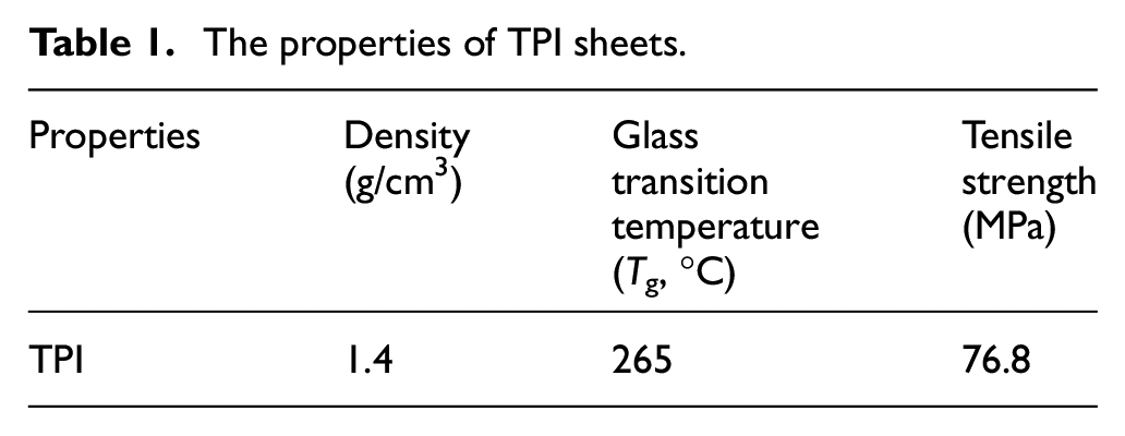
The dimensions of the TPI sheet matrix were 5 mm × 100 mm × 200 mm. The properties of TPI sheets were listed in Table 1.
The properties of TPI sheets.
The FSSW equipment was modified by the CNC milling machine, as shown in Figure 1. The FSSW tool which made of 1045 steel had a tri-flute pin, as shown in Figure 2. Schematic of different steps of FSSW process in this study is shown in Figure 3. Firstly, the rotational tool moved to the top of the TPI sheet, as shown in Figure 3(a). Secondly, the tool plunged into the TPI sheet until the shoulder contacted with the upper sheet, and the shoulder penetrated 0.2 mm in the upper TPI sheet, as shown in Figure 3(b). The friction heat which resulted from the contact between the tool and workpiece softened the TPI materials, and the materials between upper sheet and bottom sheet mixing because of the stirring of FSSW tool, as shown in Figure 3(c). Finally, the rotation tool was retracted upward, and the welding joint was completed, as shown in Figure 3(d).
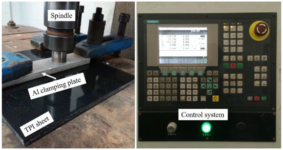
The FSSW equipment.
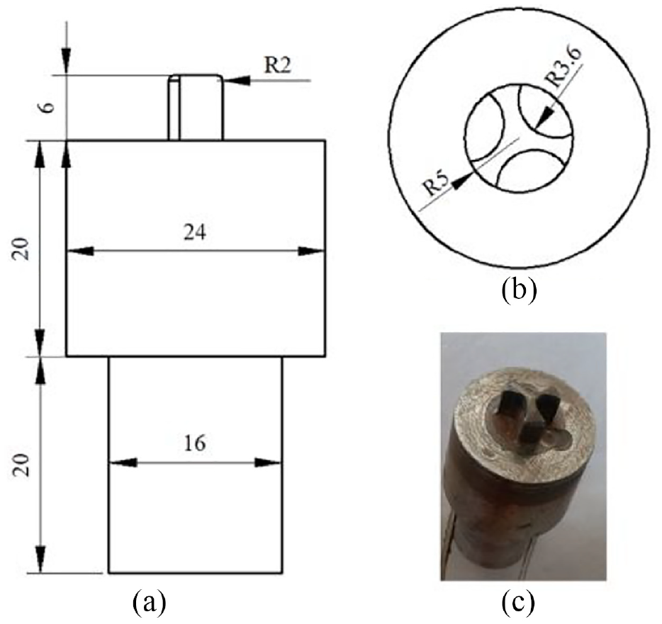
The FSSW tool: (a) front view, (b) top view, and(c) photo view.
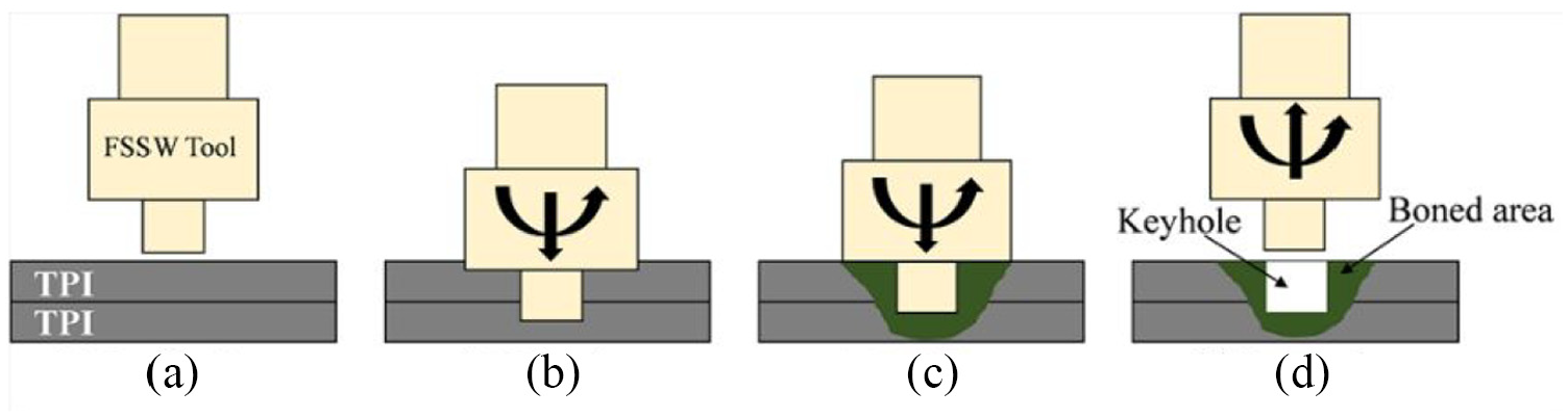
Schematic of different steps of FSSW process in this study: (a) positioning, (b) plunging, (c) mixing, and (d) retracting.
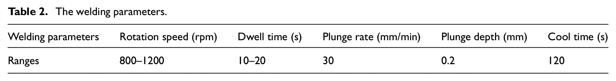
The welding parameters are shown in Table 2. Based on previous research, the plunge rate, plunge depth (the depth of the shoulder plunged into the upper surface of the PI plate) and cool time in this research, were 30 mm/min, 0.2 mm and 120 s, respectively. The rotation speed and dwell time were set as 800–1200 rpm and 10–20 s.
The welding parameters.
GQ-300 Leica optical microscope (OM), Zeiss-Supra 55 and XL-30ESEM scanning electron microscope (SEM) were used for analysing the microstructure of the joint and fracture. Lap-shear tests were carried out by CMT 5105 SANS microcomputer control electronic universal tensile testing machine at room temperature (20°C) according to ASTM D638-10. The experimental results were obtained via averaging the tensile strengths of three specimens. The thermal behaviour of the composites was analysed by DSC 8500 differential scanning calorimetry (DSC), and the heating rate was 10°C/min at 20°C–400°C.
Results and discussion
Figure 4 shows the joint surface in different rotation speed when the dwell time is 10 s. The joints produced with rotation speed of 800 rpm, 1000 rpm and 1200 rpm are shown in Figure 4(a) to (c). When the rotation speed was 800 rpm, continuous gap defects was produced between the shoulder affect zone and the pin affect zone, as shown in Figure 4(d). With the increase of the rotation speed from 800 rpm to 1000 rpm and 1200 rpm, the gap defects in the transition zone between the shoulder affect zone and the pin affect zone were disappeared, as shown in Figure 4(e) and (f). Meanwhile, it can be seen that the shoulder affect zone and the pin affect zone appeared different colour from Figure 4. The shoulder affect zone was yellow, which resulted from the accumulation of incompletely assimilated TPI. With the increase of the rotation speed, the accumulation of the TPI materials was tapering off. When the dwell time is 20 s, the surface morphology of joints is shown in Figure 5. Compared with Figures 4 and 5, it can be seen the boundary of the shoulder affect zone and the pin affect zone was no clear when the dwell time increased from 10 s to 20 s. At the same rotation speed (800 rpm), the gap defects in the shoulder affect zone and the pin affect zone were from continuous to scattered. The yellow powder area derived from the mechanical mixing of TPI was disappear because of more heat when the dwell time was 20 s.
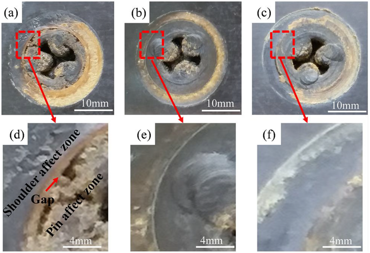
The surface of joints in different rotation speed at the dwell time of 10 s: (a) 800 rpm, (b) 1000 rpm, (c) 1200 rpm, (d) the larger image of Figure 4a, (e) the larger image of Figure 4b, and (f) the larger image of Figure 4c.
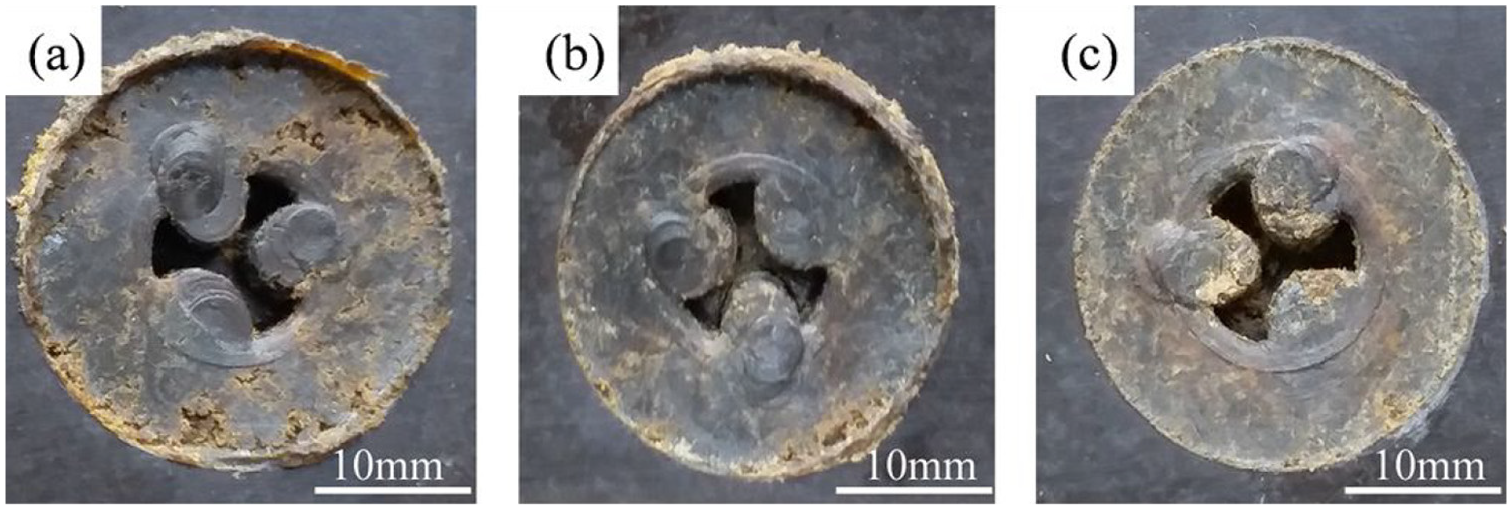
The surface of joints in different rotation speed at the dwell time of 20 s: (a) 800 rpm, (b) 1000 rpm, and (c) 1200 rpm.
Two factors can be used for explaining the above phenomenon. Firstly, when the dwell time was 10 s, the friction heat which produced in low rotation speed (800 rpm) was less, and the TPI materials was incomplete melting. During FSSW process, the friction forces between the shoulder and TPI materials was increased, which made the surface of TPI joints rough. With the increase of the rotation speed, the friction heat was also increased. The TPI materials was complete melting, and it resulted in the smooth surface. Secondly, it could enhanced liquidity of the TPI joint materials via increasing the dwell time. A relatively high surface forming quality was obtained at a longer time. Compared with Figures 4(a) to (c) and 5(a) to (c), it can be seen the materials mixing was more fully, and there were no clear boundaries between the shoulder affect zone and the pin affect zone when increased the dwell time from 10 s to 20 s. Further analysed Figures 4 and 5, it found that the surface roughness of the TPI joints increased with the increase of the dwell time at the same rotation speed. It was due to the viscosity between shoulder and TPI materials increased with the increase of the friction time, which made a layer of TPI materials adhered on the shoulder. The friction from the shoulder and TPI to TPI adhesion layer and TPI materials. So the surface was rough at a long dwell time. However, the TPI molecular chains could get diffused sufficiently with the increase of the friction time, and the intermolecular chains bond was better.
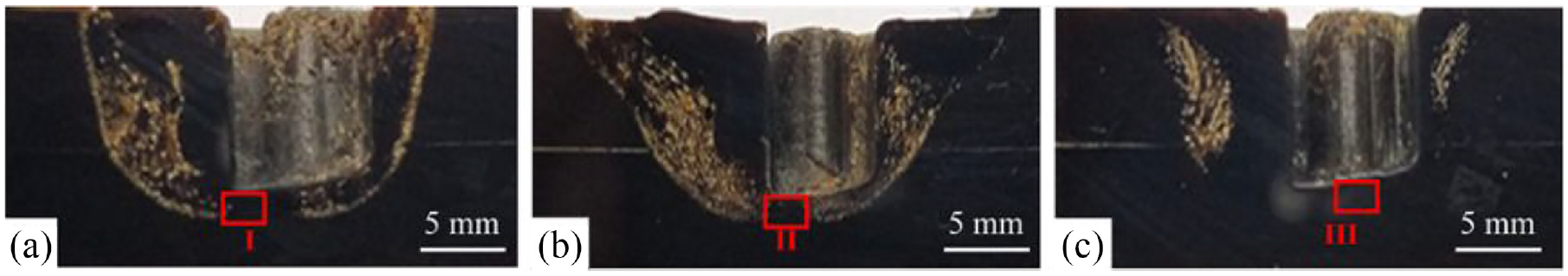
Figure 6 shows the cross sections of joint in different welding parameters. The voids are found in all samples. It due to the character of the TPI materials itself. But for all this, the TPI joints which produced in different rotation speed and dwell time still showed different characteristics. When the dwell time was 10 s, the cross sections of the joint in different rotation speed are shown in Figure 6(a) to (c). It can be seen the voids were less and more dispersed distribution with the increase of the rotation speed. The TPI materials was stirred and squeezed during FSSW process. The rotation speed was very important to the stirring of the TPI. Increasing the rotation speed could generate more friction heat and strong shear effect. The number of the voids reduced with the increase of the rotation speed due to the enhancement of the materials flow. Further analysing Figure 6(b)(I) and (II), it can be seen the voids under the stir pin was less than that on other location, and the microstructure is shown in Figure 7. During FSSW process, the materials of the welding surface migrated to the end of the pin, which formed the extrusion zone. This process could eliminate the internal voids.
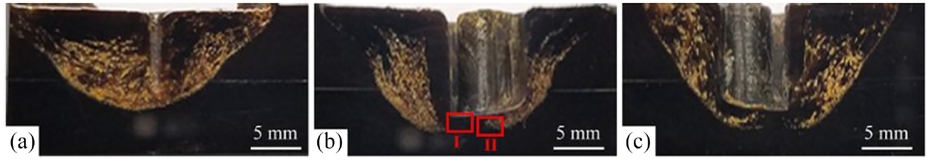
The cross sections of joints produced in rotation speed at the dwell time of 10 s: (a) 800 rpm, (b) 1000 rpm, and(c) 1200 rpm.
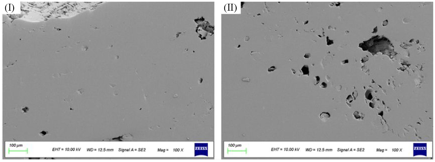
The magnification of the regions marked by rectangle I and II in Figure 6(b).
Increasing the dwell time from 10 s to 20 s, the number of the void was significantly less, as shown in Figure 8(a) to (c). Long dwell time could increase the mixing time of the TPI materials and reduce the materials viscosity, which made the structure was denser. However, increasing the rotation speed and dwell time could increase the heat input, and the high rotation speed and long dwell time was must to TPI welding joint. Figure 9 gives the microstructure of the regions marked by rectangle I, II and III in Figure 8, which also corroborated that it was advantageous to the TPI materials forming by increasing rotation speed.
The cross sections of joints produced in rotation speed at the dwell time of 20 s: (a) 800 rpm, (b) 1000 rpm, and(c) 1200 rpm.
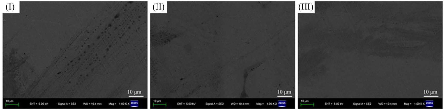
The microstructure of the regions marked by rectangle I, II and III in Figure 8.
Figure 10 indicates the shear strength test results of the joints in different rotation speed and dwell time. The results show that the shear strength increased with the increase of the rotation speed and dwell time. The maximal shear strength was 65.7 MPa, which was obtained when the rotation speed and dwell time were 1200 rpm and 20 s, respectively. On the one hand, increasing rotation speed could increase the heat input and the materials mixing degree. It was beneficial for the TPI materials with poor mobility and high melting temperature. On the other hand, increasing the dwell time could make the TPI materials stirred thoroughly and mixed evenly, which improved the shear strength.
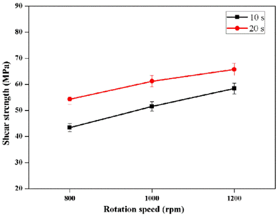
Shear strength results of the FSSW joints.
Figure 11 shows the fracture surface morphologies of the tensile shear samples. The joints was a smoother surface when the dwell time was 10 s because of the lack of joining, as shown in Figure 11(a) to (c). It meant that the dwell time of 10 s was less and the plastic deformation was insufficient. When the dwell time was 20 s, the fracture surface of the joints was rough, particularly that the rotation speed of 1200 rpm, as shown in Figure 11(d) to (f). Meanwhile, worth emphasising was that increasing rotation speed accelerated the plastic deformation degree of TPI materials 30 when compared with Figure 11(a) to (c) or (d) to (f).
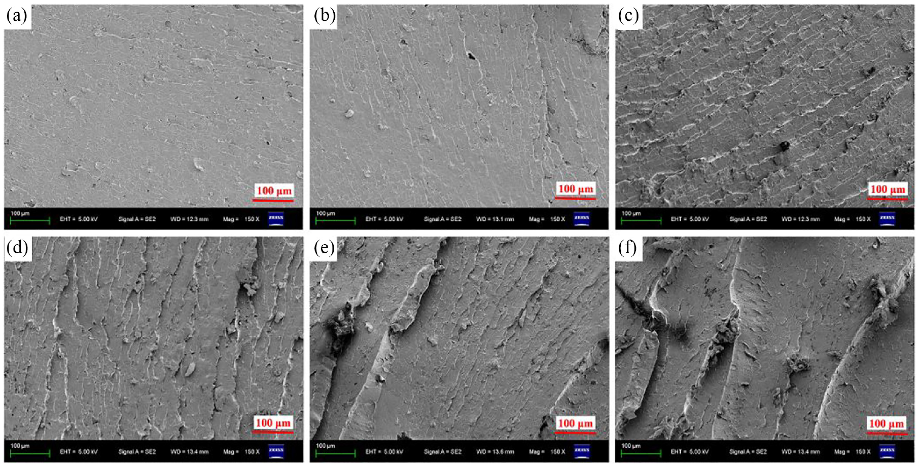
Fracture surfaces of the FSSW joint at different rotation speed and dwell time: (a) 800 rpm and 10 s, (b) 1000 rpm and 10 s, (c) 1200 rpm and 10 s, (d) 800 rpm and 20 s, (e) 1000 rpm and 20 s, and (f) 1200 rpm and 20 s.
Take the sample at the rotation speed of 1200 rpm and the dwell time of 20 s for example, the DSC results of different regions is shown in Figure 12. As can be seen in Figure 12, all region (including the base matrix, marked in A) displayed the similar curve with a Tg around 265°C. The results indicated that the melting behaviour of different regions was no obvious difference.
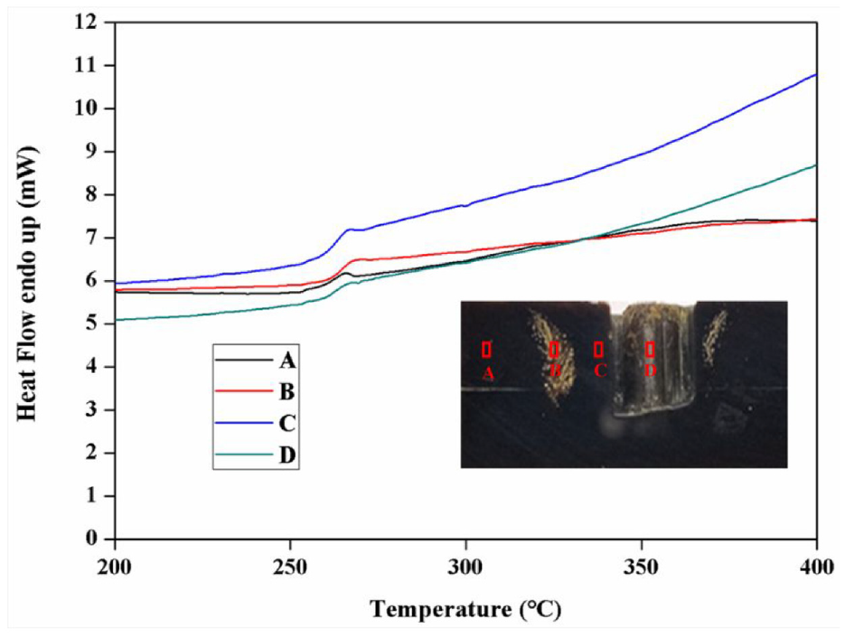
DSC of the different regions of TPI joint at the rotation speed of 1200 rpm and the dwell time of 20 s.
Conclusions
The TPI sheets were successfully joined via FSSW technology. The effect of rotation speed and dwell time on the microstructure and shear strength was studied. The results was summed up as follows:
(1) The gap defects were formed with a low rotation speed due to insufficient heat input and materials flow. The surface roughness of the TPI joints increased with the increase of the dwell time at the same rotation speed.
(2) The shear strength was increasing when increasing the rotation speed and dwell time. The maximal shear strength (85.5% of TPI matrix) was obtained when the rotation speed and dwell time were 1200 rpm and 20 s, respectively.
(3) The DSC results indicated that the melting behaviour of different regions was no obvious difference.
(4) The TPI joint had potential application prospect in the field of electrical, mechanical and aerospace industries.
Footnotes
Declaration of conflicting interests
The author(s) declared no potential conflicts of interest with respect to the research, authorship, and/or publication of this article.
Funding
The author(s) disclosed receipt of the following financial support for the research, authorship, and/or publication of this article: This work was supported by Project funded by National Natural Science Foundation of China (51705450), Natural Science Foundation of the Jiangsu Higher Education Institutions of China (18KJB460031), Technological Innovation Nurturing Foundation of Yangzhou University (2019CXJ046), Science and Innovation Fund for college students of Yangzhou University, China Postdoctoral Science Foundation (2018 M642337).