
Abstract
This article presents an industrial feasible approach to robustly joining dissimilar materials of AA6061-T6 and 1Cr18Ni9Ti using refill friction stir spot welding processes and the associated joints assessment. The microstructure and shear strength property tests are taken on the dissimilar joints of 2-mm-thick plates. The results indicate that the microstructure change of the joints can be categorized in stir zone, heat-affected zone, thermomechanically affected zone and base material. The 1Cr18Ni9Ti material is squeezed toward the 6061-T6 material and forms the hook tissue, which enhances the mechanical properties of the refill friction stir spot welding–enabled joints of two dissimilar materials. The shear strength of the joints increases at first and then decreases with increase in the tool rotational speed, the indentation depth, the axial force and welding time. When the welding process is carried out at the tool rotational speed of 1800 r/min, indentation depth of 2.3 mm, the axial force of 15.65 kN and the welding time in 7.5 s, the maximum shear strength of the joints can be achieved as being able to take the loading of 8650 N as experimentally tested.
Keywords
Introduction
Dissimilar joining of aluminum to steel gains more and more attention particularly in aerospace, aviation, automotive, shipbuilding and railway industries, mainly because of its intriguing advantages such as weight saving, improved hybrid structural strength, and energy-resource efficiency and cost reduction.1–3 Resistance spot welding (RSW) and riveting are the primary methods employed currently for spot-like joints for structural components. Previous literature 4 pointed out that the joining of dissimilar materials by RSW is quite challenging due to their difference particularly in chemical, mechanical and thermal properties. Furthermore, there is high energy consumption, poor weld strength and shunting problems associated with RSW technology applications. Riveting will increase the weight of components and the additional drilling as needed will increase the cost. There exists low production efficiency, poor and noisy working environment, requirement for additional sealants and coping with corrosion problems as resulted from riveting. 5
Friction stir spot welding (FSSW) was developed as an alternative technology to overcome these issues above, by being capable of replacing RSW and riveting in some applications. Conventional FSSW was invented by Mazda Motor Corporation in 1993, 6 which is similar in concept and appearance to its predecessor friction stir welding (FSW). It consists of three stages, that is, plunging, stirring and retracting. 7 The process can also be called as basic friction stir spot welding (BFSSW). Mazda Motor Corporation has successfully applied BFSSW technology in the production of the rear doors of their 2003 RX-8 car model, which rendered the rear doors with much improved structural stability against the side impact as well as providing the five star roll over protection. 8 However, there also exists a disadvantage for the BFSSW, that is, the joint having a characteristic keyhole in the middle, which significantly decreases the mechanical properties of the joints. In addition, the corrosion likely takes place preferentially at the keyhole because of the rainwater in the keyhole, where the body paints hardly reaching its bottom. 9
In order to overcome the problem, refill friction stir spot welding (RFSSW) was developed by GKSS-GmbH in 2003. 10 The schematic illustration of the RFSSW process is shown in Figure 1. It can be seen that the RFSSW is performed using a tool assembly comprising three parts: the clamping ring, the sleeve and the pin. They are mounted coaxially and operated by three separate actuators in such a way that they can move up and down independently. Both the pin and the sleeve are connected to another actuator and they can rotate in clamping ring in a same speed. As illustrated in Figure 1, the RFSSW process can be presented in four distinct stages. They are as follows:
The sheets are clamped together by the clamping ring against a backing anvil and both the pin and the sleeve start to rotate, which produces frictional heat on the upper sheet surface and thus leads to the localized plasticization.
The pin and sleeve are moved against each other axially, with the sleeve driving into the material and the pin making a room for the displaced material.
After a predetermined plunge depth is reached, the process is reversed, the sleeve is withdrawn and the pin presses the material into the space provided.
The joint is completed once the sleeve has returned to their original position, and a smooth even surface has been created. The clamping force will be upheld until the joining process has been completed. 11
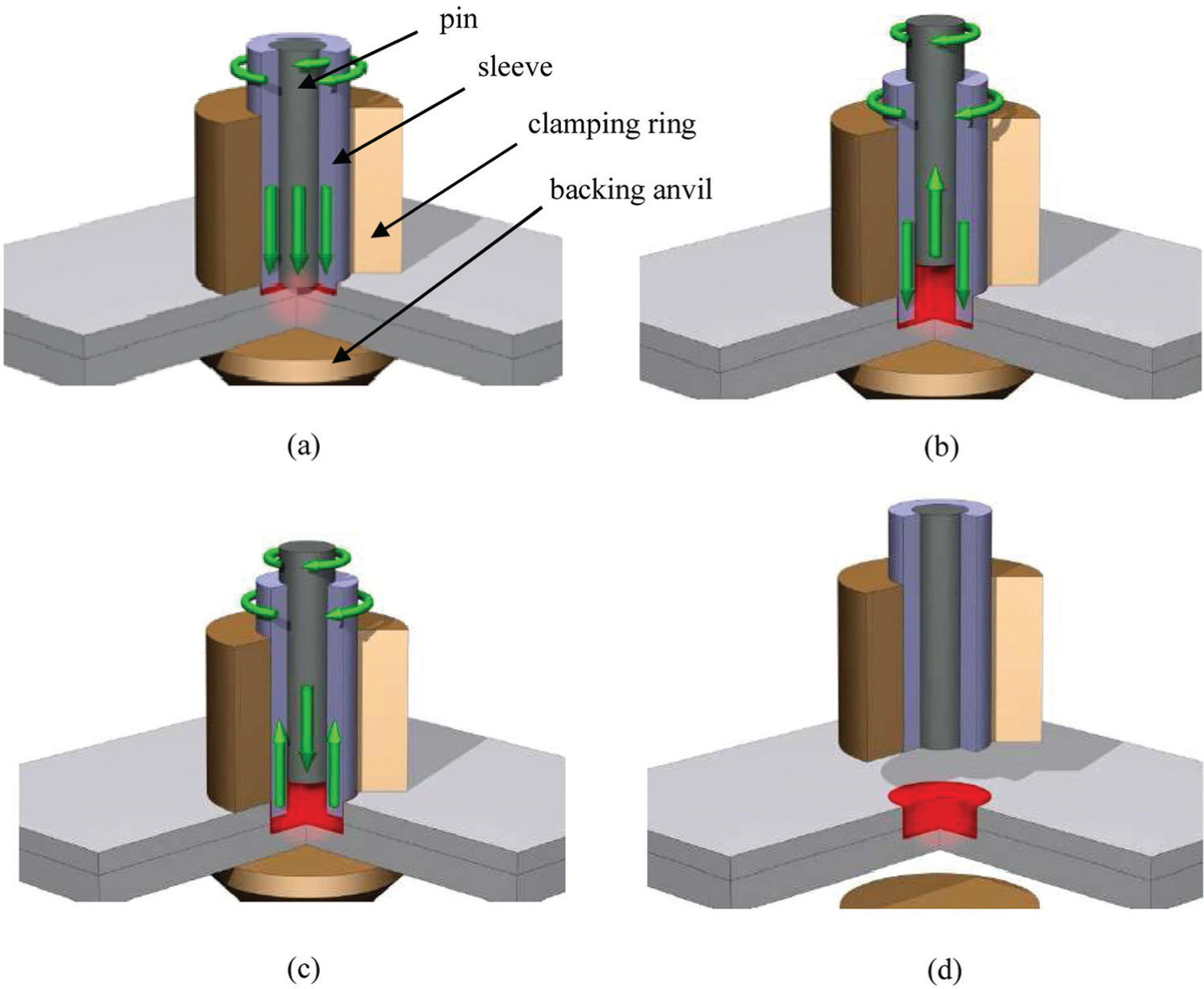
Schematic illustration of the RFSSW processes: 10 (a) clamping, (b) intrusion, (c) extrusion, (d) unclamping
Prakash and Muthukumaran 12 investigated Al–Mg–Si aluminum joint using RFSSW, it had higher strength than the joint made by BFSSW because the refilling process increased the effective cross-sectional area of the nugget. Uematsu et al. 9 also reported that the RFSSW process improved tensile strength by about 30%. However, because of the complex procedures and associated high cost, there are fewer applications of the RFSSW process as it progresses. There are very few published research literatures, except a few research papers, on using the RFSSW process for joining the same materials such as aluminum alloys. There is no report on using RFSSW for joining the dissimilar materials of aluminum alloys and steels.
In the research presented in this article, experimental investigation was conducted using lap-shear specimens of RFSSW dissimilarly joining between 6061-T6 and 1Cr18Ni9Ti materials. The mechanical properties were evaluated and the microstructure, characteristics of defects, and failure mechanisms were further assessed based on experimental testing and observations. The results of the process trials show the capability of using the RFSSW process for joining the dissimilar materials of 6061-T6 and 1Cr18Ni9Ti, in particular.
Experimental testing preparation and testing methods
The materials used for welding, in this study, were a 2-mm thick 6061-T6 aluminum plate and a 2-mm thick 1Cr18Ni9Ti steel plate. The chemical composition and mechanical properties of 6061-T6 aluminum alloys are listed in Tables 1 and 2, respectively. The chemical composition and mechanical properties of 1Cr18Ni9Ti steel are listed in Tables 3 and 4, respectively.
Chemical compositions of 6061-T6 aluminum alloys (wt%).
Mechanical properties of 6061-T6 aluminum alloys.
Chemical compositions of 1Cr18Ni9Ti steel (wt%).
Mechanical properties of 1Cr18Ni9Ti steel.
RFSSW welding experiments were carried out on the FSSW-SK-002 welding machine, as seen in Figure 2(a), which was produced by Shanghai Aerospace Equipment Manufacturer (SAEM). Rotating speed (n), welding time (t) and penetration depth (h) can be set and edited through welding menu in the man–machine interface at the front of FSSW-SK-002. Axial pressure (F) can be adjusted by gas–liquid booster cylinder control valve. The RFSSW tool employed was the FSSW-SK-GJ003, as seen in Figure 2(b), which was also produced by SAEM. The tool comprises a clamping ring, a sleeve and a pin, whose outer diameters are 18, 9 and 5.2 mm, respectively.
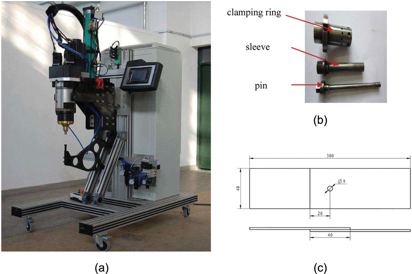
RFSSW testing setup, tools and specimen: (a) RFSSW machine: FSSW-SK-002, (b) RFSSW tools: FSSW-SK-GJ003 and (c) the test specimen of the RFSSW joint.
The 6061-T6 aluminum and 1Cr18Ni9Ti steel specimens should be wiped with acetone to remove oil, coatings and other impurities before welding. The wiping area should be wider than the zone pressed by the clamping ring. The shear joints were made in a lap configuration, as is shown in Figure 2(c), with each plate being 40 mm wide by 170 mm long. Two sheets were overlapped by 40 mm and then affixed into the welding instrument using a fixture in preparation for joining. After welding, the specimens should be cut in a direction perpendicular to the welding spot. And then, metallographic preparation should be done and sectional morphology should be analyzed. The lap-shear test was performed using the universal testing machine CMT-5305. The microstructure of specimens is observed and analyzed in the microscope Observer.D1m and Discovery.V20.
Experimental testing results and analysis
Microstructure analysis of the spot-welded joint
As shown in Figure 3(a), there are no exit hole, flash, burrs and other defects on the surface of the spot-welded joint. The surface is very smooth, and two circle boundaries are visible to the human eye: the outer boundary is between clamping ring area and sleeve area and the inner boundary is between sleeve area and pin area. A very shallow annulus-shaped indentation exists around the joint, which is mainly caused by the clamping ring pressure. The materials in the indentation area effectively prevent overflow of the material in sleeve area and also prevent the plasticized material outward to form burrs.
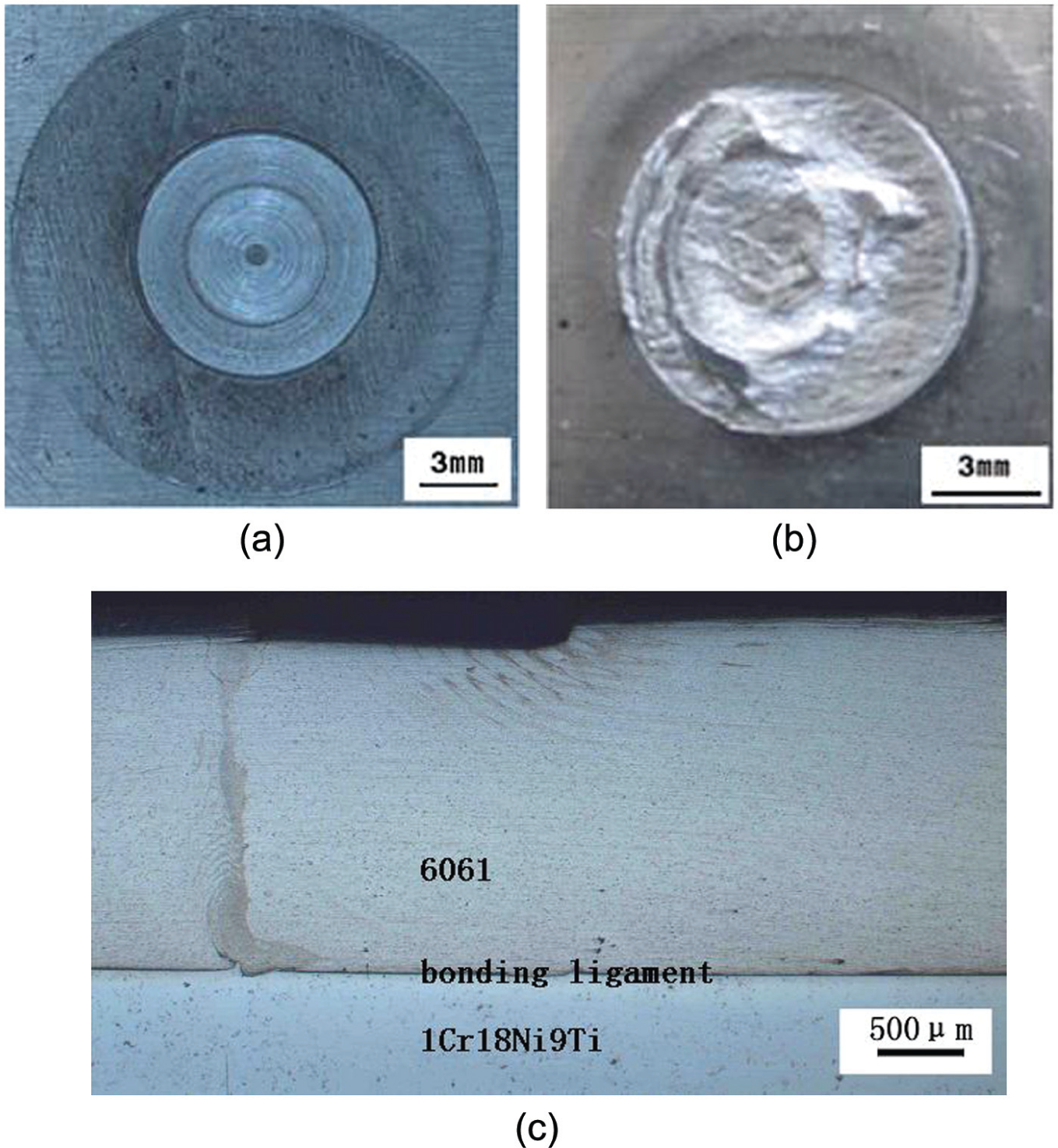
Macro/microscopic appearance of the RFSSW joint: (a) joint appearance, (b) joint tensile fracture appearance and (c) joint section.
As shown in Figure 3(b), there are 6061 and 1Cr18Ni9Ti mutual interpenetration bite organization at the breaking area of joints, this organization is similar to Bonding Ligament.
As shown in Figure 3(c), the upper plate is 6061 aluminum alloy, the lower plate is 1Cr18Ni9Ti stainless steel, and a clear interface which is known as Bonding Ligament exists between the two plates in the spot-welded joint section. The Bonding Ligament is actually formed by the plastic material flow and mixture on the spot joint of the two plates with the movement of the sleeve and the pin. It will improve the joint adhesion and increase the shear resistance and tensile resistance. While it is similar to welding inclusions and easy to cause strain concentration, it results in decrease in mechanical properties when it is subjected to the applied dynamic load. 13
As shown in Figure 4(a), a microstructural investigation revealed four distinct RFSSW weld regions: base material (BM), heat-affected zone (HAZ), thermomechanically affected zone (TMAZ) and stir zone (SZ). They are aligned from the outside to the center joint. The structural distribution is similar to the joint of the same aluminum alloy. The HAZ experienced thermal cycles during welding, grains and the second-phase particles are coarser than that of the BM, and the grain growth is more obvious particularly in the thickness direction. TMAZ is at the junction area the sleeve and the clamping ring work. The zone experienced moderate temperature cycles, dynamic recrystallization did not occur and the grain of the zone changed dramatically in size and elongated along the flow direction. The SZ is at the area the sleeve and pin work. The zone is affected mostly by thermal and mechanical flow because of stirring and experienced sharp temperature and stress change; dynamic recrystallization occurs and produces dense tiny isometric crystal tissue. Near the pin working area, the material morphology is much different from that of BM. It is affected greatly by thermal coupling; the recrystallization is much deeper, and the structure is even better than that of the joint center.
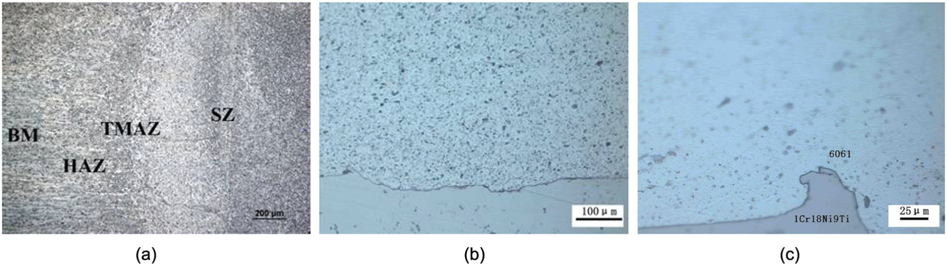
Microscopic appearance of the RFSSW joint: (a) organizational characteristics, (b) joint center and (c) joint hook.
As shown in Figure 4(b), the interface of the two plates is undulating in the joint center; the material in this area endures the stirring pressure from the tool (pin and sleeve) and the counterforce from the 1Cr18Ni9Ti plate. A part of atoms of 6061-T6 plate diffuses into the 1Cr18Ni9Ti plate. With increasing the contact area between the two materials, the tensile properties of joint are enhanced because of attractive force between the two types of atoms.
For the joint of the same kind of materials, such as aluminum alloy, Badarinarayan et al. 14 pointed out that hook organization is caused by the surface oxide membrane, and in the contact surfaces, it forms separation zone partly or fully. Yuhuan et al. 15 believe that the presence of the hook of the same kind of material damages the continuity of the joint; when the joint subjected to the applied load, the crack defects always expanse along the hook area. The hook tissue binding region size is the important factor of affected FSW joint’s mechanical properties; the larger the combined width, the better the mechanical properties of welding joints. As shown in Figure 4(c), at the junction area, the sleeve and clamping ring work, the 1Cr18Ni9Ti material squeezes toward 6061-T6 and forms the hook shape structure with the sleeve stirring, and the 6061 material penetrates into the 1Cr18Ni9Ti around the hook area. The hook tissue increases mixed area between the two plates and improves the mechanical properties of welding joints.
Shear testing results and analysis
As shown in Figure 5(a), when the welding time and axial pressure are constant, the maximum shearing force of the joint changes with the change in tool rotating speed (n) and penetration depth (h). Different curves represent different penetration depths where the penetration depths equal 1.8, 2.0, 2.1, 2.3 and 2.4 mm. With the increase in the penetration depth (h), the maximum shearing force of the joint increases at first and then reduces. The maximum shearing force reaches optimum when the penetration depth (h) is 2.3 mm. It can be seen from Figure 5(a) and (b), with the increase in the tool rotating speed (n), the maximum shearing force of the joint increases at first and then reduces. No matter what kind of penetration depth is used, the maximum shearing force reaches optimum when the tool rotating speed is 1800 r/min.
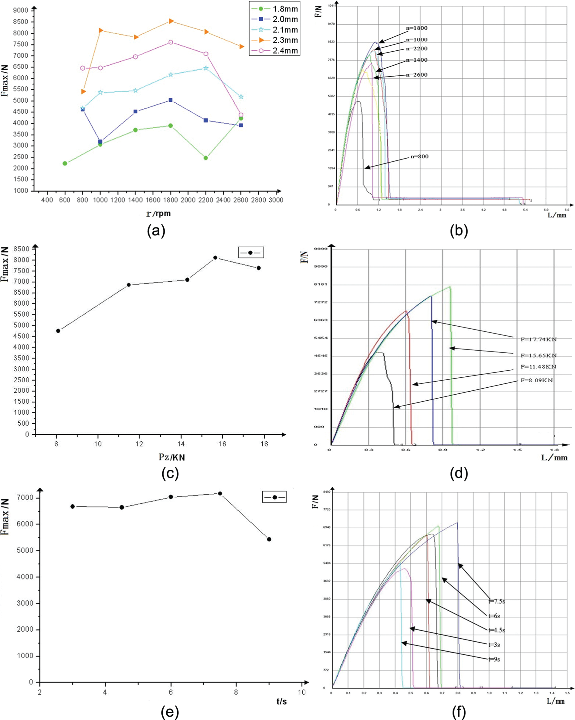
Shear testing results and the analysis: (a) relationship between the processing parameters and strength, (b) relationship between the tool rotational speed and load–displacement curve, (c) relationship between the axial pressure and strength (n = 2200 r/min, t = 3.5 s), (d) relationship between the axial pressure and load–displacement curve, (e) relationship between the action time and strength (n = 2200 r/min, F = 13.56 kN) and (f) relationship between the action time and load–displacement curve.
It can be seen from Figure 5(c) and (d), with the increase in axial force (F), the maximum shearing force of the joint increases at first and then reduces. The maximum shearing force reaches optimum when the axial force is 15.65 kN. If the axial force is too small, the plastic material may outflow from the gap of the clamping ring and the upper 6061-T6 plate and form flash and cavity defects because of lack of material and decrease in the mechanical properties of the joint. If the axial force is too large, the annulus-shaped indentation around the joint will be deeper under the clamping ring pressure. The height in this zone will be thinner than in other zones and decrease the mechanical properties of the two plates.
As shown in Figure 5(e) and (f), with the increase in welding time (t), the maximum shearing force of the joint increases at first and then decreases. The maximum shearing force reaches optimum when the welding time is 7.5 s.
If the welding time is too short or the tool rotating speed is too low, the heat produced by the tool stirring is not enough and the material is not plasticized adequately in the joint, the material flow cannot keep up with the tool movement and lead many cavity defects, and the maximum shearing tense will be decreased. If the welding time is too long or the tool rotating speed is too high, the heat produced by the tool stirring is too much and the material in the joint is overheated to make it much soft, the joint will be thinner under the tool pressure, and the maximum shearing tense will be decreased.
The shear performance test of five groups of specimens is conducted employing the optimized processing parameters: tool rotating speed of 1800 r/min, indentation depth of 2.3 mm, axial force of 15.65 kN, and welding time of 7.5 s, the maximum shearing force of the dissimilar joint can cope with the loads up to 8650 N.
Conclusion
In this article, the dissimilar joining process of AA6061-T6 and 1Cr18Ni9Ti using RFSSW was presented; the microstructure and shear strength property tests on the joints were carried out particularly with the 2-mm-thick plate specimens. The research conclusions can be drawn up as follows:
Microstructure of the welding joint is presented and categorized into four zones, that is, SZ, HAZ, TMAZ and BM, which helps lead to better understanding of the process mechanism. The 1Cr18Ni9Ti material is squeezed toward 6061-T6 and the hook is formed, which helps improve the mechanical properties of welding joints.
With increase in the tool rotational speed, the penetration depth, axial force and the welding time, the maximum shearing force of the dissimilar joint increases at first and then decreases.
The maximum shearing force on the dissimilar joint can cope with loads up to 8650 N, and the joining process is performed under the process parameters at the tool rotational speed of 1800 r/min, the indentation depth of 2.3 mm, the axial force of 15.65 kN and the welding time of 7.5 s.
Footnotes
Declaration of conflicting interests
The author(s) declared no potential conflicts of interest with respect to the research, authorship and/or publication of this article.
Funding
The author(s) disclosed receipt of the following financial support for the research, authorship, and/or publication of this article: This work was financially supported by the China Scholarships Council (CSC).