
Abstract
The conventional tooth surface of a face gear is difficult to manufacture, and the cutter for the face gear cutting is not uniform even though the parameters of the pinion mating with the face gear slightly change. Based on the analysis of the geometry features of the tooth surface, a new developable ruled surface is defined as the tooth flank of the face gear, for which the most important geometry feature is that the flank could be represented by a family of straight lines, hence it could be generated by a straight-edged cutter. The mathematical models of the new ruled tooth surface, the cutter and the generation method are presented, the deviation between the ruled surface and the conventional surface, the correction of the ruled surface to reduce the deviation are investigated through numerical examples. The manufacturing process is simulated by VERICUT software, and the results demonstrate that even when the principle deviation is added to the machined deviation, the absolute deviation is on the micro-scale. The meshing and contact simulation shows that the new surface could obtain good meshing performance when the number of face gear teeth is greater than three times the number of pinion teeth. This research provides a new method for manufacturing face gears.
Introduction
Face gear drives are an important form of angular transmission because these devices have some special advantages1,2; however, face gear drives are not used in a sufficiently wide range of applications. One of the primary reasons for this lack of usage is the low processing efficiency of these devices, which limits large-scale production and leads to high application costs. Moreover, the surface profile of a face gear tooth is regarded as a unique complex space. A face gear tooth is considered an undevelopable ruled surface according to the theory proposed by Litvin et al.,1–3 which limits the development of new face gear generation methods. However, most manufacturing methods for face gears currently depend on this theory.4–10
The surface of a face gear tooth is defined by it mates with a spur pinion. Hence, the simplest method for machining a face gear is the application of a shaping device that is identical to the pinion.1–4 However, this method can only be used for soft or low-precision tooth surfaces. The tools used to generate face gears containing hard or high-precision tooth surfaces are worm cutters or grinders 10 and disk cutters or grinders,5–9 which both duplicate the involute of the pinion. Although the indexing motion of the worm cutters/grinders is continuous, the generated surfaces are in point contact, the tool needs transverse motion in the longitudinal direction to process the whole tooth surface, and the processing efficiency is not very high. The processing efficiency of disk cutters/grinders is much lower than that of the worm cutters/grinders because of the single-tooth indexing and transverse motion.
Furthermore, it is impossible to standardize the cutting tools through involute duplication. A milling cutter whose generating line is the involute of an imaginary shaper was applied by Wang et al. 11 to improve the machining accuracy and production efficiency of face gears. Shi et al. 12 designed a swept surface for a worm that is used in face gears grinding, and the worm could be dressed by a generation approach based on the involute surface of a shaper. For continuous finishing face gears, a shaving method was proposed by Wang et al., 13 the shaving cutter is a helical gear and meshes with a spur involute shaper. Chu et al. 14 applied a disk wheel in face gears grinding, to improve the grinding efficiency, the trajectory of the disk is the contact line of the face gear and an imaginary shaper, the author defined the working surface of the disk through the shaper, in fact, if the face gear is machined in this way, the disk profile is not need to constrain. 15 To facilitate backlash adjustment, Zhou et al. 16 studied a kind of face gear meshing with a tapered involute pinion, the face gear is also generated by a tapered involute shaper or a worm that is defined by the shaper. Generally, in these studies, the shaper is slightly different from the pinion, which means that the corresponding cutter has to be changed with the pinion.
To standardize the cutter and increase the processing efficiency, Stadtfeld17,18 proposed the use of a Coniflex cutter for bevel gear machining, in which they modified the cutter rotation to make the plane of the cutter simulate the involute of the pinion. In theory, the plane of the cutter should be in point contact with the face gear tooth surface; however, in practice, the generated tooth surface is constrained in line contact with the plane, which results in a large or macroscopic deviation between the generated and theoretical surfaces. 19 Tang and Yang20,21 proposed milling and planning methods for face gear generation using simple tools. Although the accuracy of the tooth surface was guaranteed, all of these methods are profiling approaches, and the surfaces of the work-piece and cutter are in point contact. Kubo and Ueda 22 claimed that gear geometry should be regarded as a function of the production method, and an example of an invo-planar bevel gear demonstrated that the cutting time was greatly reduced and a smoother tooth flank was obtained. From these results and considering the manufacturing difficulty of the conventional tooth surface of the face gear, the geometry of the face gear may need to be changed.
Based on a conventional face gear, the surface features of the face gear tooth are analyzed, introducing a new geometry definition in which the tooth surface of the face gear could be represented by a developable ruled surface. A method is also applied to correct the surface to increase precision. If these corrections are neglected, the tooth surface must be modified to improve the unloaded meshing performance. A method using a 5-axis planer for face gear manufacturing is proposed, which enables the generation of face gear tooth surfaces with a straight-edged cutter. Mathematical models for the cutter and numerical control (NC) motion are established. The results in this study indicate good meshing performance and high cutting precision, which are simulated by tooth contact analysis (TCA) and VERICUT (NC verification software), respectively. Due to the lack of financial support, the manufacturing experiment could not be provided with this paper, but for the visualization of the manufacturing process, a simulation video which is available on the web: https://v.qq.com/x/page/z3133gsj38v.html is provided with this paper.
New geometry definition for a face gear
Conventional geometry
Figure 1 shows a face gear meshed with a spur pinion (i = 1) or a shaper (i = s). Litvin et al.1,2 elaborated the generation of the tooth surface of a face gear in detail; herein, this information is briefly introduced to lay the foundation for this paper. It is assumed that the position and unit normal vectors of the involute surface Σ
i
of the pinion and shaper are represented by


where


where Ns and N2 are the numbers of teeth in the shaper and face gear, respectively. The parameters in Figure 1 are the shaft angle γ between zi and z2, the inner radius L1 constrained by undercutting, the outer radius L2 constrained by pointing, and the axode cone angles γi and γ2 measured from the instantaneous axis O2P to axes z i and z2, wherein radius rpi of pitch circle of gear i.
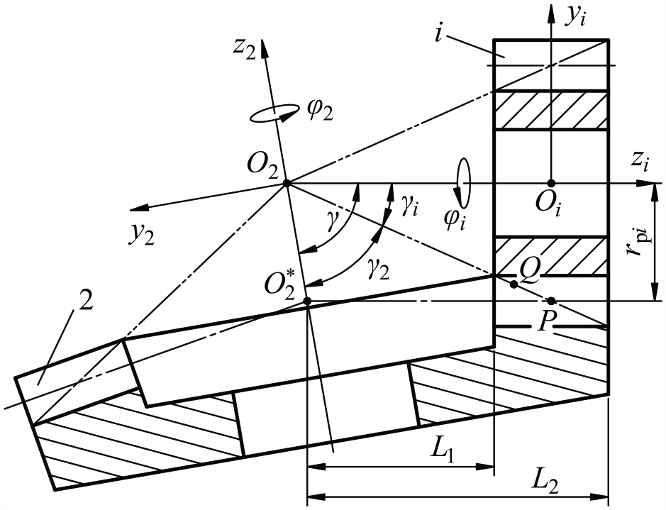
Face gear meshed with a pinion (i = 1) or a shaper (i = s).
Equations (1)–(4) and Figure 1 completely describe tooth surface Σ2, which could be used in numerical calculations, gear modeling, and surface feature analysis.
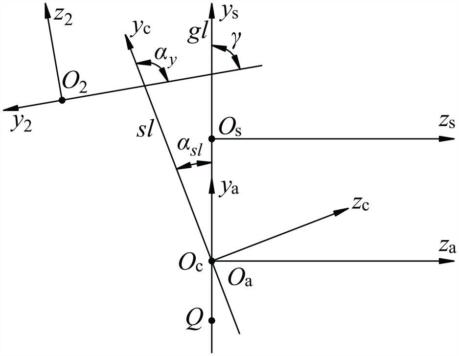
A special contact line
Figure 2 shows a special contact line L2s when surface Σ2 is meshed with Σs at rotation angles φs and φ2 of 0, in which L2s extends from the top of the toe to the root of the heel. A view of the end face reveals that L2s is an involute with the same profile as the shaper because the line lies in surface Σs. Any point on L2s is tangent to the involute marked by inv in surface Σs and the straight line marked by sl in surface Σ2. L2s is also tangent to the profile line gl, which is usually used in the drawing surface Σ2, the angle from this line to axis y2 is equal to γ. Moreover, an angle, which is referred to as the differential angle in Section 2.5, exists between lines sl and gl (an enlarged view of this angle is shown in Figure 2).
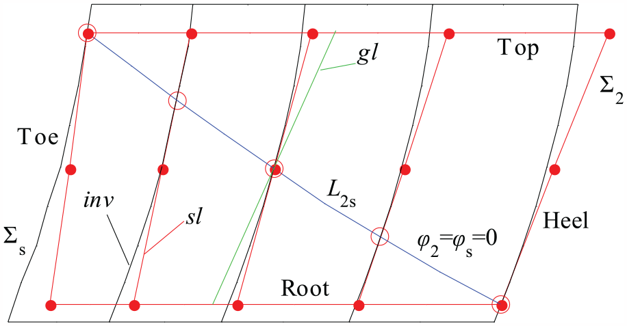
A special contact line in surfaces Σs and Σ2.
The most important phenomenon shown in Figure 2 is that L2s is an involute extending in the longitudinal direction of the face gear tooth that is tangent to the involute inv in Σs and the straight line sl in Σ2 at a point where the three lines have the same normal. Hence, based on this phenomenon, from the aspect of simplifying face gear manufacturing, researchers must determine if surface Σ2 could be regarded as a family of straight lines that are tangent either to L2s at different cross sections or to the end face involute at different points that are arranged in the longitudinal direction of the face gear tooth and change with respect to the pressure angle. If this conclusion is true, which means that the tooth surface of the face gear can be generated by a straight-edged cutter, the surfaces of the face gear tooth and cutter will be in line contact, which means a high cutting efficiency.
Straight line deviation
The straight line sl deviates from surface Σ2, and it is valuable to consider the range of this deviation to determine whether the deviation could be ignored.
We try to assess this deviation through a numerical method. As the direction of the straight line is unknown, it is necessary to determine the direction of the straight line by using two points at first, then using the third point to check out whether the equation of the straight line is satisfied, on the other hand the any one of these points in surface has three unknowns have to be solved, therefore three points in surface Σ2 are used to determine the straight line and automatically find its direction. Then, the deviation is calculated, and the corresponding steps are elucidated hereafter:
(1) A point in surface Σ2 with a pitch cone
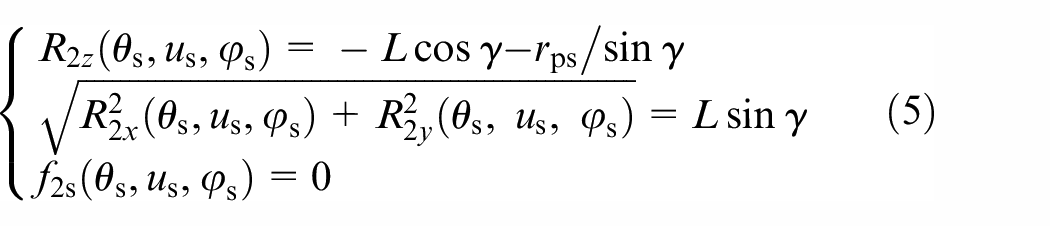
where R2i (i = x, y, z) is the component of vector
(2) Another tooth surface Σ# 2 is introduced that is the same as Σ2, and the corresponding position vector, surface parameters and meshing equation are marked with a superscript #. Accordingly, the equation of the straight line in Σ2 could be expressed as follows:
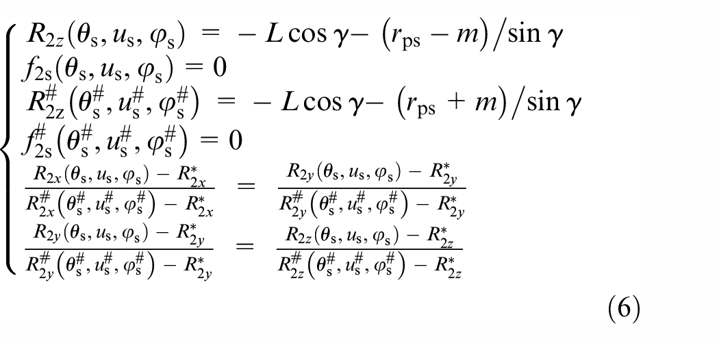
where m is the module of the face gear pair and the other two points on the lines are located at the top and root of the tooth. The straight line is represented by the fifth and sixth formulas listed in equation (6). The direction angles measured from the straight line to axis i2 (i = x, y, z) are represented with equation (7).
(3) After solving equations (5)–(7), the straight line could be represented by equation (8), where xsl, ysl, zsl are the coordinates of the point on the straight line in S2. In this step, zsl is replaced with the tooth height, and xsl and ysl are solved with equation (8). Then, in the neighborhood of the straight line, any point on the surface Σ2 is solved by equations (1) and (4), and the corresponding deviation is calculated by equation (9).
Developable ruled surface for face gears
The deviation represented in equation (9) and the differential angle in Section 2.5 are ignored here, and will be discussed in Section 2.5 and Section 5.1.
Comparing the instantaneous axis O2P in Figure 1 and the special contact line L2s in Figure 2, their directions are consistent; in fact, at any point Q on instantaneous axis O2P, the linear velocities of the shaper and face gear are equal, which are represented as follows:

where rQ and LQ are the distances from point Q to axes zs and z2, respectively, and ωs and ω2 are the angular velocities of the shaper and face gear, respectively. As shown in Figure 3, any point on the involute, rQ can be expressed as follows:
where rbs = rpscosα is the radius of the basic circle of the shaper and α is the pressure angle of the face gear pair. Hence, LQ can be expressed as shown in equation (12).

In S2, LQ represents the position of the origin Oa (Figure 3) on the contact line L2s (Figure 2) in the longitudinal direction of the face gear tooth, and the instantaneous center of origin Oa is Q.
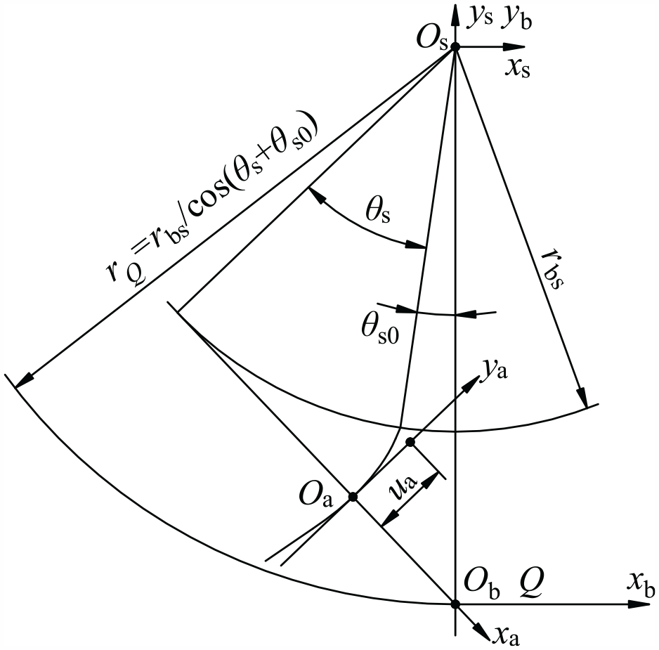
Involute and tangent line at any point.
As shown in Figure 2, the contact line L2s could be regarded as a longitudinal generating line of the tooth surface for a face gear, and the profile curve is a straight line sl that is tangent to L2s. In this way, a new tooth surface was designed for the face gear.
When viewed from the end face of the shaper, the contact line L2s is an involute, as shown in Figures 2 and 3. By taking equation (12) into consideration, the position and unit normal vectors


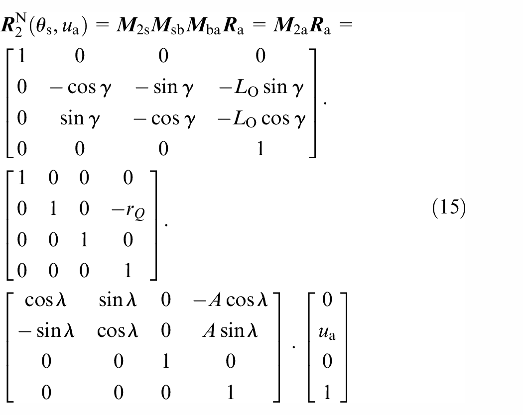
where λ = θs+θs0,
According to the information elaborated above, the essential differences between ΣN2 and Σ2 are as follows: (1) Σ2 is an envelope of the family of surfaces Σs, whereas ΣN2 is a family of tangent lines used when creating the involute L2s in surface Σs; (2) Σ2 is an undeveloped ruled surface, whereas ΣN2 is a developable ruled surface according to the theory of differential geometry. 23
Correction for the new tooth surface
Because of the intersecting axes zs and z2 and the face gear rotating around z2, in the xaOaya plane (Figure 3), for the shaper, the normal vector of any point on the involute at any rotational angle can pass through instantaneous center Q, but for the face gear, the profile curve is defined as straight line ya (or sl), on which one and only one point’s normal vector at rotational angle φ2 = φs = 0 can pass through Q, the only one point is origin Oa, when the straight line rotates with the face gear around axis z2, at other rotational angle φ2 = N2φs/Ns ≠ 0, the point whose normal vector can passes throng Q, is conjugate with the involute, must locate either one side of the straight line with a certain arc length in the longitudinal direction, the rotation around axis z2 causes the arc length of differential which creates the angle between lines sl and gl. This angle is referred to as the differential angle because it reflects the differential arc length.
To simplify the manufacturing process of a face gear, it is not necessary to consider applying the differential angle to correct the new tooth surface ΣN2. The reasons this is unnecessary are presented hereafter. (1) Obtaining good meshing performance is more important than pursuing microscopic precision. (2) A conventional face gear is not completely conjugated to its mating pinion because the pinion (number of teeth = N1) has 1–3 fewer teeth than the shaper (number of teeth = Ns).1,2 (3) Some types of gear drives do not have a standard or theoretical tooth surface, so the tooth surfaces are defined by the meshing performance.24–26 This idea is also applicable to a face gear with a developable ruled surface. For example, the tooth surface of the pinion, which has fewer teeth and is easier to machine, could be redefined using the conjugation principle and then modified. (4) A small scale differential angle is not easy to control on the machine tool. Hence, another form of NC is needed to regulate the differential angle, thereby increasing the operational cost of the machine tool.
However, the differential angle is beneficial for reducing or minimizing the surface ΣN2deviation from Σ2; therefore, the differential angle is presented here as a method to reduce the deviation of surface ΣN2.
The differential angle, denoted αsl in plane ysOszs, is shown in Figure 4, in which the involute and its tangent line and the profile line gl of surface Σ2 overlap on axis ys. According to Figure 4, surface ΣN2 can be corrected as follows:
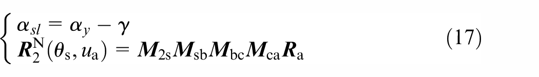
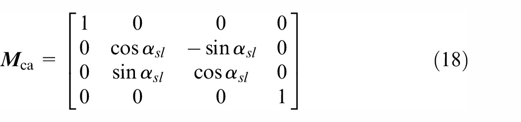
where
Sketch of the differential angle between lines sl and gl.
New surface cutting method
Cutter design
Because ΣN2 is a developable ruled surface, a finger-shaped cutter, cylindrical milling cutter, cone disk milling cutter, or planing cutter (shown in Figure 5) could be used to machine a face gear with surface ΣN2. If the conical surface of the cone disk is covered with abrasive materials, it becomes a grinding wheel that could be used to grind the face gear.
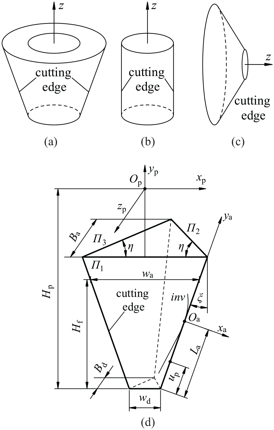
Suitable cutters for new tooth surface generation: (a) finger-shaped cutter, (b) cylindrical milling cutter, (c) cone disk milling cutter/grinding wheel, and (d) planing cutter.
As planing is the most suitable approach to illustrate face gear generation with a straight-edged cutter, a planing cutter (Figure 5(d)) is used as an example to elaborate the manufacturing process.
The geometry of the planing cutter is shown in Figure 5(d). The cutting plane is denoted Π1, which is similar to the cross section of a straight rack. The angle η between planes Π2 (or Π3) and Π1 should be less than π/2 rad; otherwise Π2 (or Π3) will interfere or cut the surface generated by Π1. Hence, the best choice for the basic body of the planing cutter is a triangular pyramid.
The planing cutter is mainly to visualize the generation of the developable ruled surface, the strength of the cutter is not considered, and the parameters are mainly constrained by the tooth space geometry.
The parameters for the planing cutter are as follows: the cutter height Hf = 2.25 m, which is the whole tooth height including the top clearance; the cutting body and handle height Hp are constrained by the machine tool; the bottom width wd and top width wa are equal to the tooth space widths of the outer root and inner top of the face gear, respectively; the bottom thickness Bd and top thickness Ba are determined by the cutter strength and cutting force (generally Bd ≤ Ba); the inclination angle ξ of the side edge should satisfy tanξ = 0.5(wa−wd)/Hf, but this is not compulsory; up is the distance from a current point on the cutting edge to the cutter bottom, according to Figure 5(d); and the position vector of the cutting edge in Sp is expressed as follows:
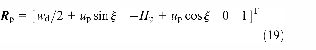
In the generation process, only the cutting edge works, so it is not necessary to give the normal vector of any surface or plane on which the cutting edge is located.
Rules of planing motion
As shown in Figures 1 and 2, and equation (15), the planing cutter can generate surface ΣN2, during which the cutter only needs three translations and a rotation. These translations alter the position of the cutter in direction i2 (i = x, y, z), whereas the rotation changes the tilting angle of the cutting edge of the cutter. After two side surfaces of a tooth are generated, the workpiece indexes, and another rotation is performed.
Figure 6 shows the structure of a 5-axis NC planer. The axes correspond to translations in the X, Y, and Z directions and rotations in the B and C directions. Therefore, the planer provides sufficient degrees of freedom to manufacture a face gear with a tooth surface ΣN2, thereby illustrating the advantages and convenience of this approach in machining face gears with a developable ruled surface ΣN2. The planer shown in Figure 6 is suitable for machining gears with an orthogonal face without loss of generality. If a nonorthogonal face gear is considered, a special fixture is needed to adjust the axis angle γ.
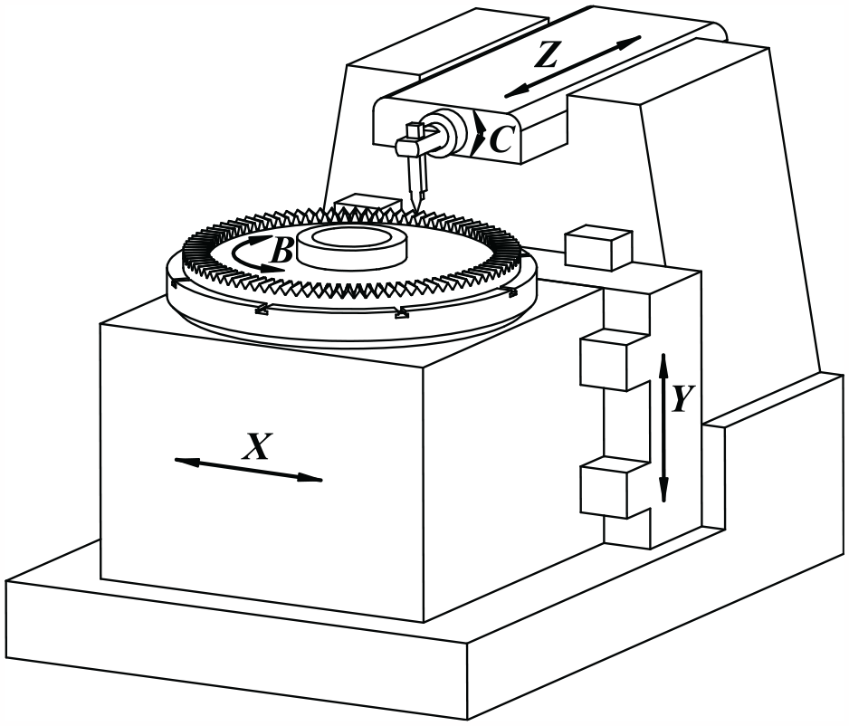
Five-axis NC planer used for face gear generation.
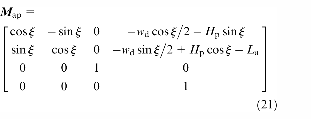
Because of the nonlinearity and implicitness of motion relationship for face gear generation by the planning cutter, it is impossible to generate the NC codes by directly using automatic programming modules of NC systems or simulation platform (e.g. VERICUT), the motion rules of the NC planer should be determined before cutting the work-piece. The equivalent principle generally used in the determination of the NC motion rules is that the position and direction of the surface generated in the NC cutting process is identical to that in the abstract or uniform generation process.27,28 Considering the structure (Figure 5(d)) of the cutting tool, the abstract generation is completely expressed by equations (20) and (21), where
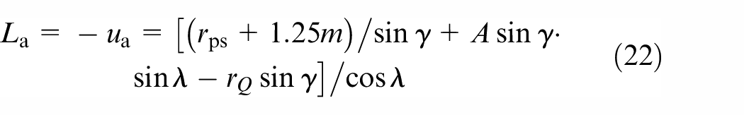
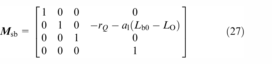
As the coordinate origin Oa is a moving point (Figure 3), the distance La is a variable parameter (Figure 5). To determine La, the bottom of the planing cutter must be able to cut the tooth root and the tooth height in the direction z2, as shown in equation (15). Hence, La can be solved with equation (22).

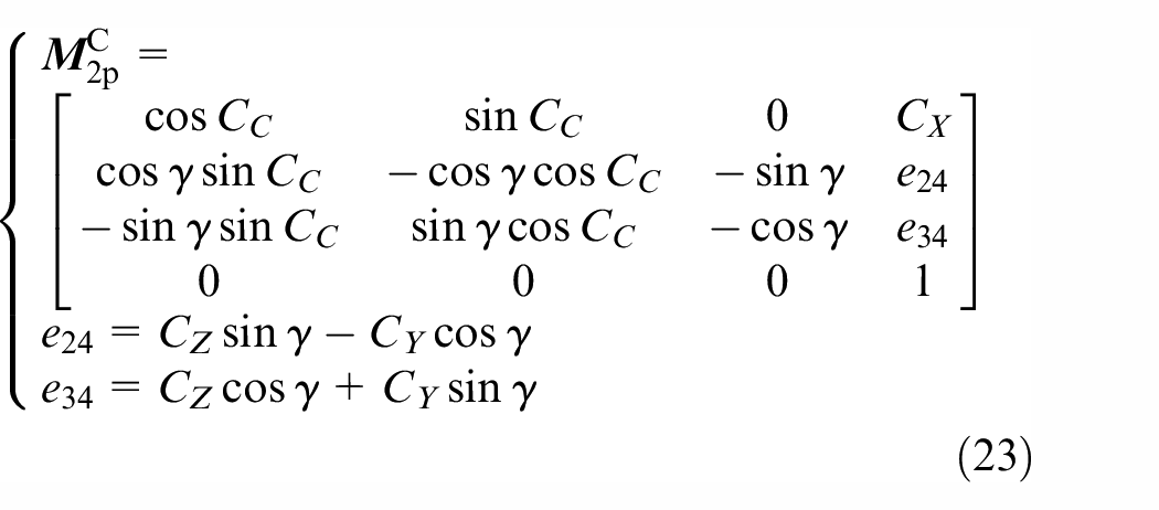
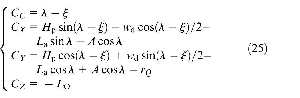
The coordinate systems for the planer are shown in Figure 7. Herein, it is assumed that the zero cutting point of the NC program is the coordinate origin O2, the systems Sp and S2 are rigidly connected to the planing cutter and the face gear, auxiliary systems Sd, Se are connected to the frame of the planer. Note that CX, CY, and CZ are three coordinates for the translational axes, CC is the rotational axis. The matrix of coordinate transformations from Sp to S2 is represented by equation (23). The equivalent principle of the planing example is shown in equation (24), in which two matrices are compared; the coordinates could be solved as shown in equation (25).
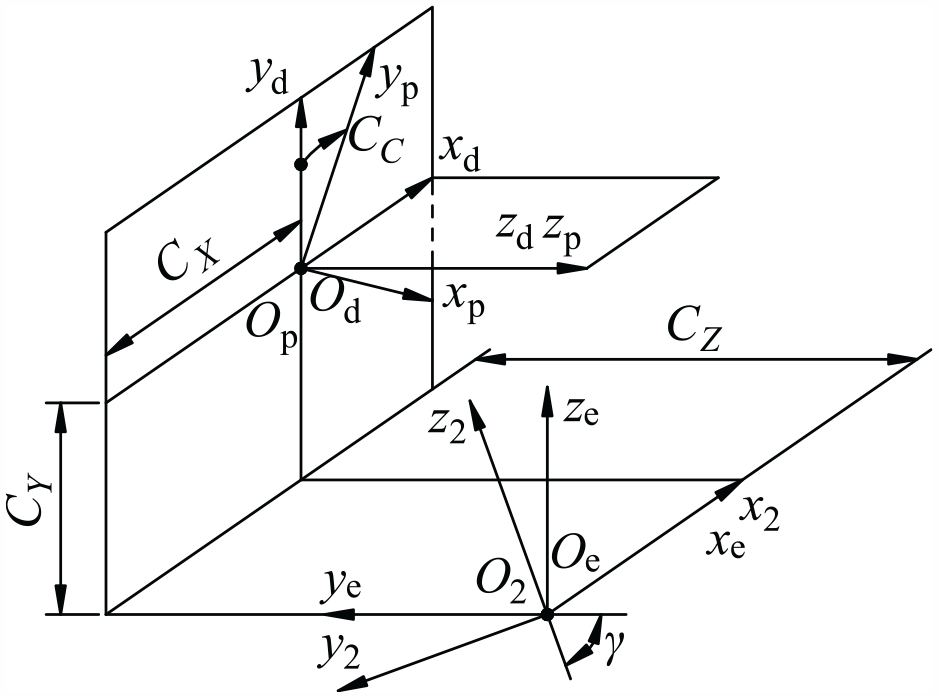
Coordinate systems for face gear generation.
The translational and rotational coordinates are functions of the generating parameter θs (λ = θs + θs0); these coordinates will be used to program the NC codes. In this paper, equation (25) is used to generate the NC codes by dispersing independent variable λ in its value range that is constrained by tooth surface boundary.

Surface crowning and TCA algorithm
Double crowning of the new tooth surface
From the aspect of manufacturing, a face gear with the newly defined tooth surface is an optimization alternative; note that good meshing performance is a requirement in this study. In the face gear with surface Σ2 generated by a shaper, the contact lines between the generating and generated surfaces under rotational angle φ2 = Nsφs/N2 ≠ 0 are approximately parallel to the special contact line L2s. Considering the defined pattern (Figures 2 and 3) of the new tooth surface, which meshes with the surface of the pinion when N1 = Ns, the two surfaces may be approximately in line contact, indicating that it is necessary to modify the tooth surface to localize the bearing contact.
Many methods have been investigated to provide better control of meshing performance,28–30 such as local synthesis and active design. However, the aims of the paper mainly focus on the proposal of the new tooth surface and its generation for a face gear. Hence, the simplest method – parabolic modification – is selected here to demonstrate that the newly defined tooth surface could obtain acceptable good meshing performance. The corresponding modification can be performed on the face gear or the pinion5,31; for the sake of brevity, the modification is only performed on the face gear in this study.
The crowning profile for the newly defined tooth surface is shown in Figure 8(a), wherein ap is the parabola coefficient in the profile direction, ua0 is used to control the position of the parabola vertex, and the vector

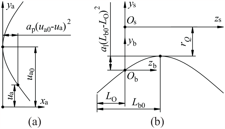
Double crowning for the newly defined tooth surface, (a) for profile crowning, (b) for longitudinal crowning.
TCA algorithm
The meshing performance is simulated by tooth contact analysis. Litvin established coordinate systems and tangent contact equations for a simulation of the meshing and contact of face gear pairs. These achievements, which are described in detail by Litvin et al.,1,2 are used directly in this study to show the performance of the newly defined tooth surface and its modified face gear when meshed with the involute surface of the pinion.
Without losing generality and ensuring the conciseness of the paper, the misalignments are not taken into consideration, and γ = π/2, the emphasis is focused on the new face gear tooth surface in meshing with the involute surface of the pinion. The coordinate systems for the surfaces meshing simulation are shown in Figure 9, S1 and S2 respectively are rigidly connected to the pinion and face gear, Sf is a fixed auxiliary coordinate system in which the gear and pinion rotate, φ1 and φ2 are the pinion’s and face gear’s rotation angles when they are in meshing, B = (Ns−N1)mn/2, when N1 and Ns are different. As shown in Figure 9 when surface ΣN2 and surface Σ1 of the pinion contact at a point on the contact path, the following formulations are obtained.
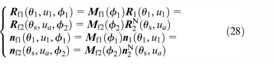
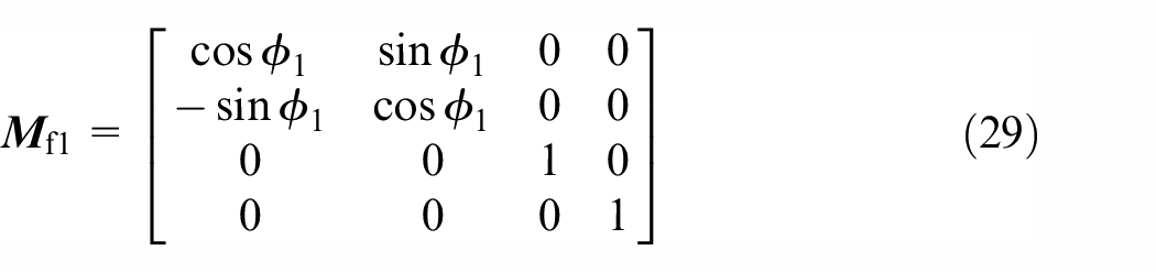
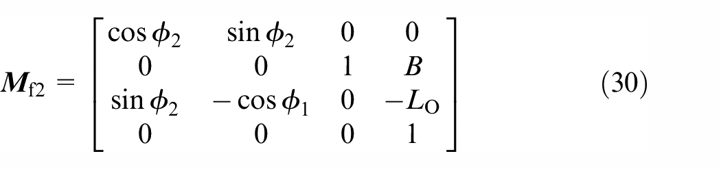
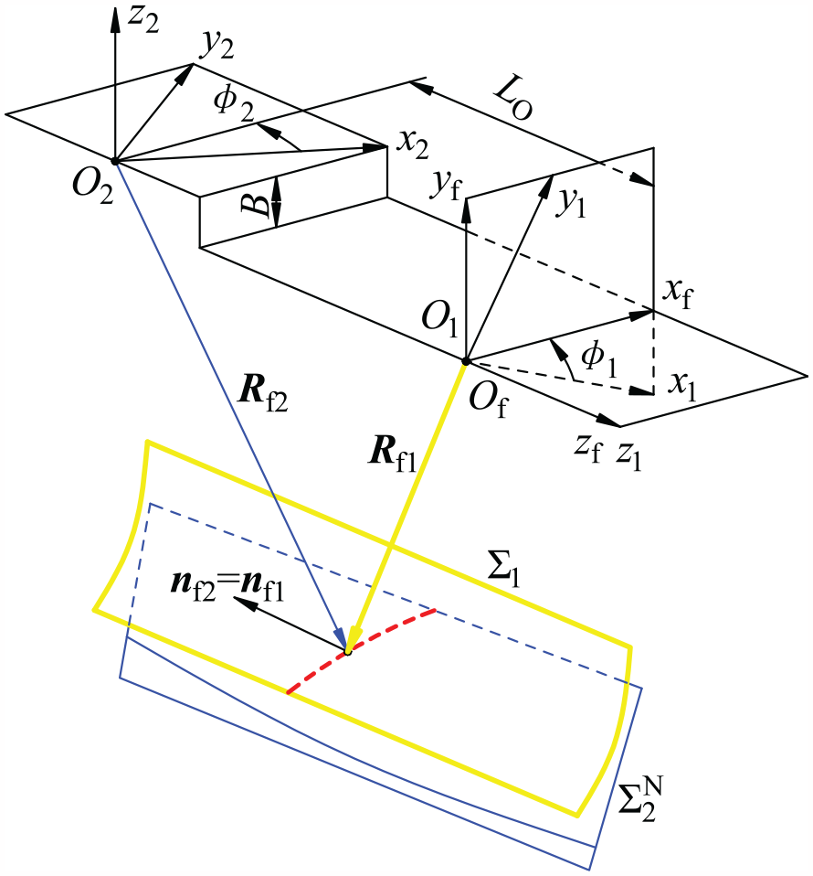
Coordinate systems for meshing simulation.
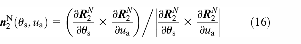
Because the module of the normal vector is equal to 1, the vector equations in equation (28) provide five scalar equations, if angle φ1 or φ2 is regarded as input, then the remaining five unknowns could be solved and determine a contact point, applying the principal curvatures and directions at the contact point could determine the contact ellipse. Transmission errors are calculated by using φ1 and φ2.
Numerical examples and discussion
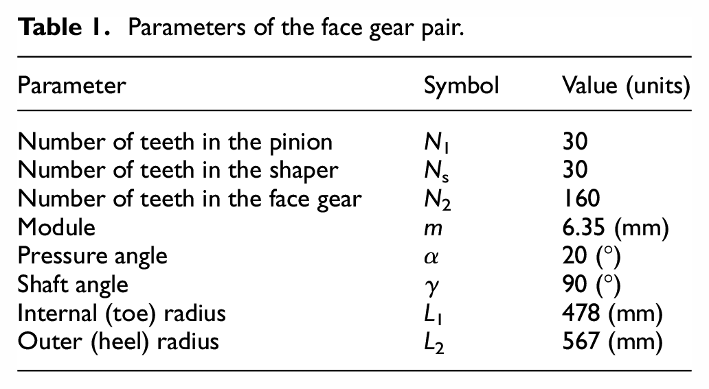
This section presents the numerical results, including (1) the deviation of the new tooth surface of the face gear, (2) the manufacturing simulation of the newly defined tooth surface and its deviation, and (3) the meshing performance of the new surface determined by TCA. The main parameters of the face gear pair are listed in Table 1, but some parameters will take different values in different numerical examples.
Parameters of the face gear pair.
New tooth surface deviation
(A) Deviation in the straight profile line. Based on equations (5) and (6), the straight line sl can be determined, and its direction angles are shown in Figure 10. Note that αx and αz can be regarded as the pressure angle and transmission angle on the cross section perpendicular to axis z2, respectively. These angles vary with respect to the radius L, and their sum is approximately equal to 90°. Note that αy reflects when sl is nearly perpendicular to coordinate axis z2. The differential angle change with respect to the generating angle θs is shown in Figure 13. The maximal and minimum differential angles respectively do not exceed 1° and −4°.
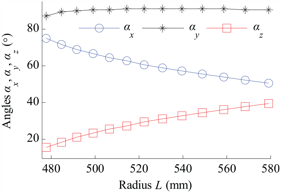
Direction angles of the straight profile line.
The deviation between the straight profile line sl and the conventional tooth surface Σ2 of the face gear is calculated by using equations (8) and (9), and the results are shown in Figure 11. The maximal deviation occurs at the corner of the root toe, which is the undercutting area, and the deviation in the rest of the area away from the corner and root approaches 0 μm. Hence, the results imply that apart from the root toe, the profile curve of the conventional tooth surface Σ2 of the face gear can be regarded as an approximately straight line.
(B) Deviation in the new developable ruled surface. Neglecting the differential angle of the straight profile line, equation (15) can be used to define a new tooth surface ΣN2 for the face gear. By applying the normal deviation of surfaces (similar to that in equation (9)), the deviation between ΣN2 and Σ2 is evaluated, and the results are shown in Figure 12. The maximum deviation occurs at the root toe, which is similar to the results shown in Figure 11; however, the magnitude of the deviation increases in Figure 12. Furthermore, a minimum deviation is smaller than that shown in Figure 11 at the top heel. In general, the deviation along the diagonal from the root of the toe to the top of the heel is larger than that along the diagonal from the top of the toe to the root of the heel.
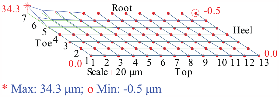
Deviation in the straight profile line.
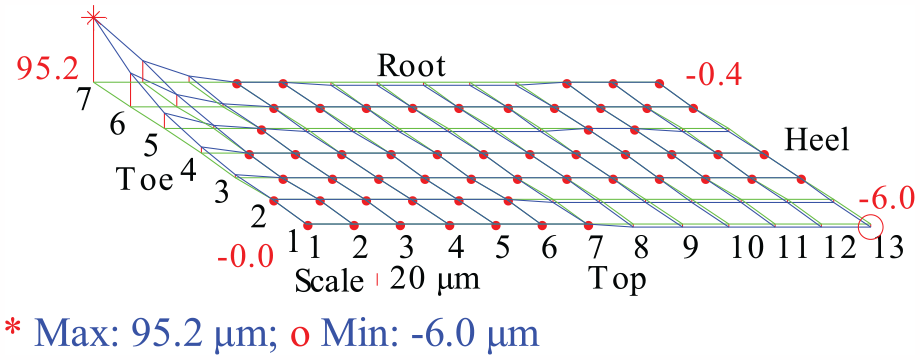
Deviation in the developable ruled surface.
Two things should be emphasized. (1) Undercutting leads to divergence of the solution, which has an influence on the accuracy of the deviation at the root toe, and increasing the internal radius or eliminating the undercutting surface will reduce the deviation and improve the accuracy of the solution. (2) The deviation along the diagonal from the root of the toe to the top of the heel decreases as the gear ratio N2/Ns increases (N2 = 160 in Figure 12, whereas N2 = 90 in Figure 16(a)), and as the number of teeth increases, the face gear becomes increasingly similar to a rack.
(C) Deviation in the new developable ruled surface after correction. The differential angle of the straight profile line can be considered a function of the generating angle θs. The function is determined by the least squares method, and the solved data and the function are shown in Figure 13. Then, the function is applied in the correction of the new surface.
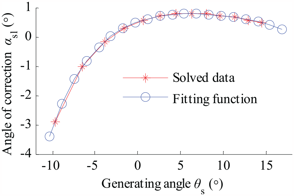
Differential angle of the straight profile line.
Figure 14 shows the correction results. The maximal and minimal errors of 9.0 and −14.6 μm, respectively, occur at points ij = 71 and 51 (i = 1, 2, …, 7; j = 1, 2, …, 13), which are located at the root toe. The correction reduces the deviation by more than a factor of 6 (95.2/14.6 = 6.52). Therefore, the differential angle is very useful for reducing the deviation, which will increase the complexity of the machining tool and the difficulty of controlling the differential angle on the machine. In some cases, the amount of tooth surface modification 32 exceeds the deviation shown in Figure 12. For these cases, we recommend ignoring the differential angle and the deviation in the developable ruled surface, and the adverse effects could be compensated by surface crowning, a conjugated pinion design, or limiting the internal radius.
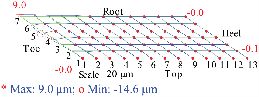
Deviation in surface ΣN2 after correction.
Manufacturing simulation
The purpose of this section is to show the process and advantages of the face gear manufactured by a cutter with a straight cutting edge, including the simplicity of the cutter, the high efficiency, and precision of the generation.
To illustrate the influence of the number of teeth on the deviation and avoid display images that are too small due to the large scale of the work-piece, the number of teeth of the face gear is decreased. The parameters of the modified face gear and the cutter are listed in Table 2.
Parameters of the modified face gear and the cutter.
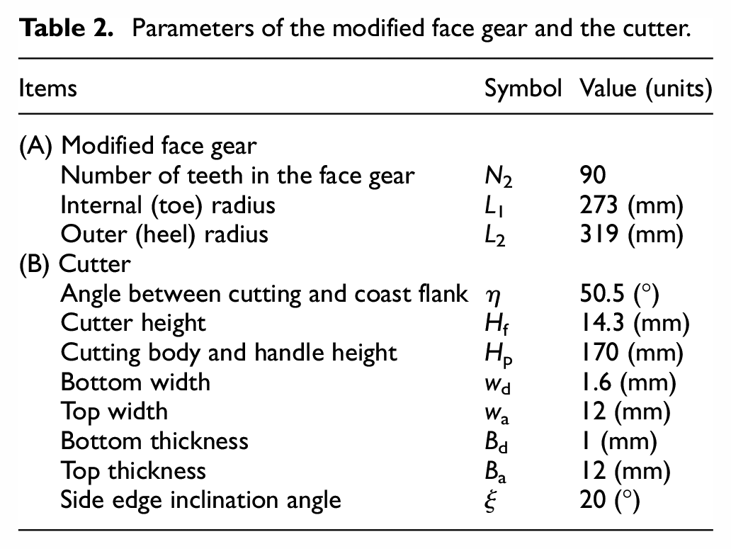
Figure 15 shows the full appearance of the cutter, whose simplicity is mainly reflected in two aspects: the cutting edge is a straight line rather than a helix involute constrained by the shape of the shaper, and the cutting body (shown in Figure 5) could be mounted on a rectangular handle like that of a lathe.
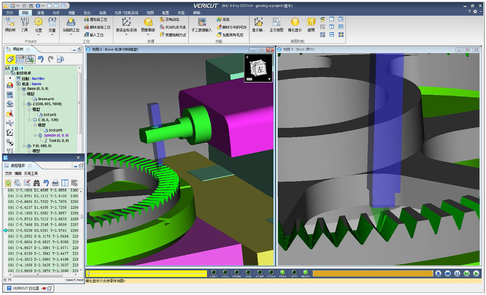
Cutting simulation for the face gear using VERICUT (its video is on the web: https://v.qq.com/x/page/z3133gsj38v.html).
Based on equation (25), the NC codes for the face gear cutting are obtained, and the codes are applied when performing the cutting simulations and error tests on the VERICUT platform. Figure 15 shows the simulation interface, part of the codes, virtual machine tool, cutter and machining work-piece. A video of the cutting simulation for the proposed method is available on the web: https://v.qq.com/x/page/z3133gsj38v.html
The high cutting efficiency is mainly reflected by the rough and finish cutting: a rough cut slot of full tooth height is shown on the right of the cutter in Figure 15. In this process, assuming the cutter has sufficient strength, the two flanks of the tooth slot, such as a rack space, could be cut by only one back and forth translation in the longitudinal direction, and the process does not require the generating motion. The finished cut slot is shown on the left of the cutter in Figure 15. One flank of the full height slot needs one back and forth translation with the generating motion, the efficiency increases considerably because the translation and generation are correlated and successive, and the cutter does not intermittently stay at individual positions along the tooth width to generate the tooth from the top to the root.
The total deviation between the newly defined developable ruled surface ΣN2 and the theoretical one Σ2 of the face gear is the sum of the principle deviation (shown in Figure 16(a)) and the machined deviation (Figure 16(c)).
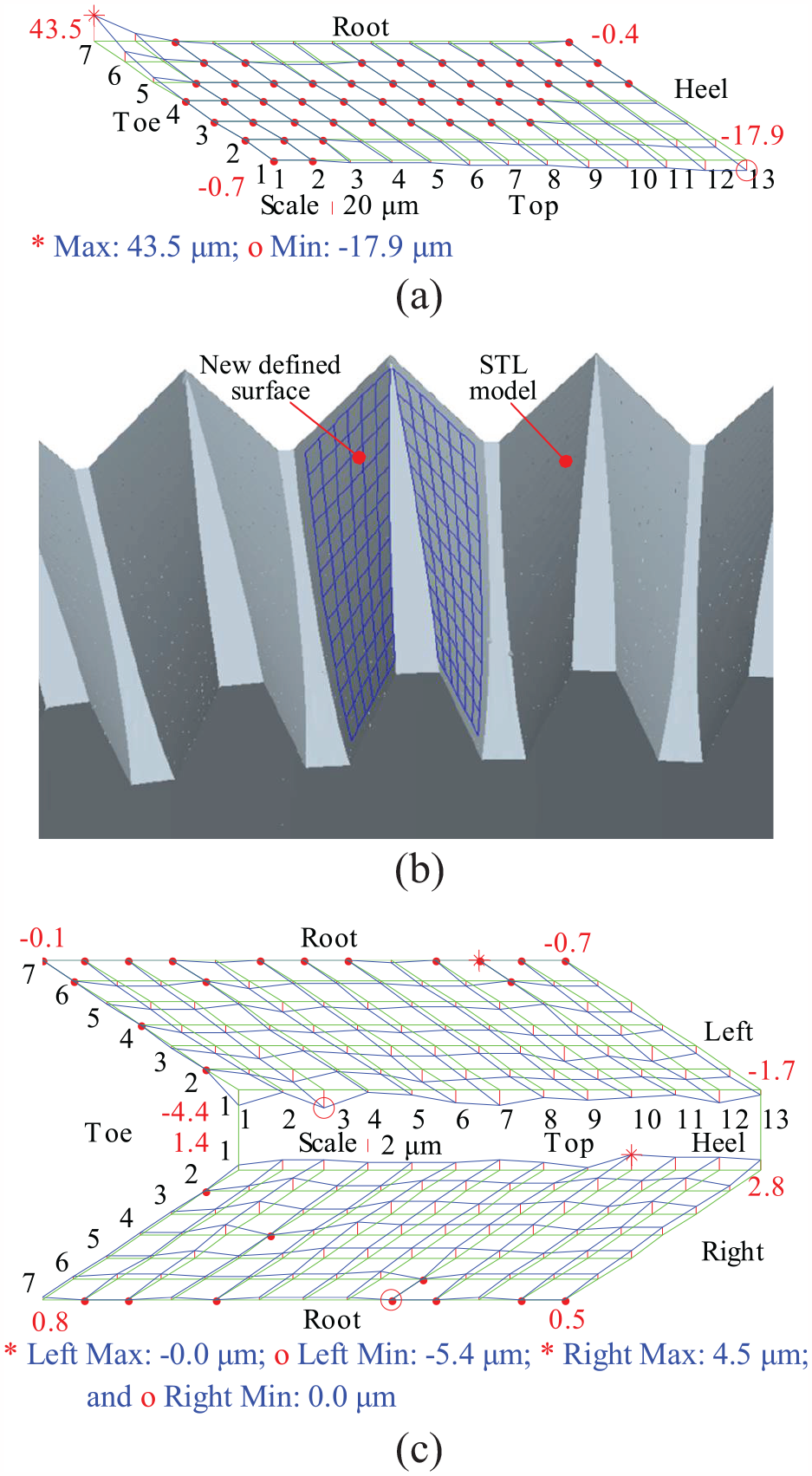
Results of the simulated tooth surface: (a) principle deviation, (b) STL model and topography for measurements, and (c) topographic deviations in the machined STL model.
After the cutting simulation, the finished face gear is exported as an STL file, as shown in Figure 16(b). The topography of the newly defined surface shown in the figure is the measuring benchmark, and the coordinates of the STL model at the node of the topography are extracted to evaluate the deviation in the machined surface. Figure 16(c) shows the results; on the left flank, the maximal deviation is −0.0 μm and the minimal deviation is −5.4 μm, whereas on the right flank, the maximal deviation is 4.5 μm and the minimal deviation is 0.0 μm. These errors, which could be caused by errors in the simulation and model transformation (e.g. in VERICUT, the tolerances of the interpolation and model transformation from VERICUT to STL are 0.05 mm), are sufficiently small to confirm the correctness and feasibility of the face gear machining method. Because the motion rules in machining simulation are theoretical, comparing to the defined surface ΣN2, the deviation of the simulated surface should be 0 μm, the actual maximum and minimum are only about one tenth of the tolerances, which fully demonstrates that the deviation is not caused by the wrong movement and design of the planing cutter.
Then, the machining precision of the face gear generated by the straight-edged cutter could be elaborated as follows. (1) If the developable ruled surface ΣN2 is defined as the face gear surface, the surface deviation does not exist. Therefore, it is very easy to obtain high precision due to the simplicity of the cutter and machining process. (2) If ΣN2 is compared with the theoretical conventional surface Σ2, the surface deviation depends on the principle deviation. Even when undercutting is taken into consideration, the absolute deviation of the gear pair does not exceed 2% (0.0952/6.35 = 0.01499, taking Figure 12 for example) of the gear pair module.
Surface meshing simulation
This section illustrates the meshing performance of the newly defined tooth surface ΣN2 of the face gear meshed with the theoretical involute surface Σ1 of the spur pinion and subsequently determines whether surface ΣN2 is able to or has the potential to obtain acceptable meshing performance, which is simulated by TCA. Four design cases in example 1 including surface crowning and one design case in example 2, whose parameters are reported in Table 3, are used to show the meshing performance; the other parameters are identical to those in Table 1. Because the aligned installation is sufficient to illustrate the meshing quality, the misalignment is not taken into consideration.
Parameters for the meshing simulation.
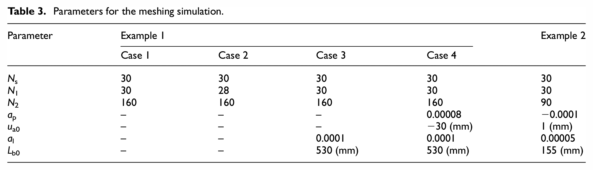
In case 1 of example 1, the surface ΣN2 is meshed with Σ1 of the pinion, for which the number of teeth is equal to the number of the teeth of the shaper and there is no surface crowning. In Figure 17(a), case 1 shows edge contact between the tooth root of the pinion and the tooth top of the face gear, whereas in Figure 17(c), case 1 shows small-scale intermittent transmission errors. This phenomenon can occur because the deviation (Figure 12) between ΣN2 and Σ2 is sufficiently small (the absolute deviation is less than 6 μm except for undercutting area i ≥ 4, j ≤ 3, i = 1, 2, …, 7; j = 1, 2, …, 13); ΣN2 is approximately conjugated to Σ1.
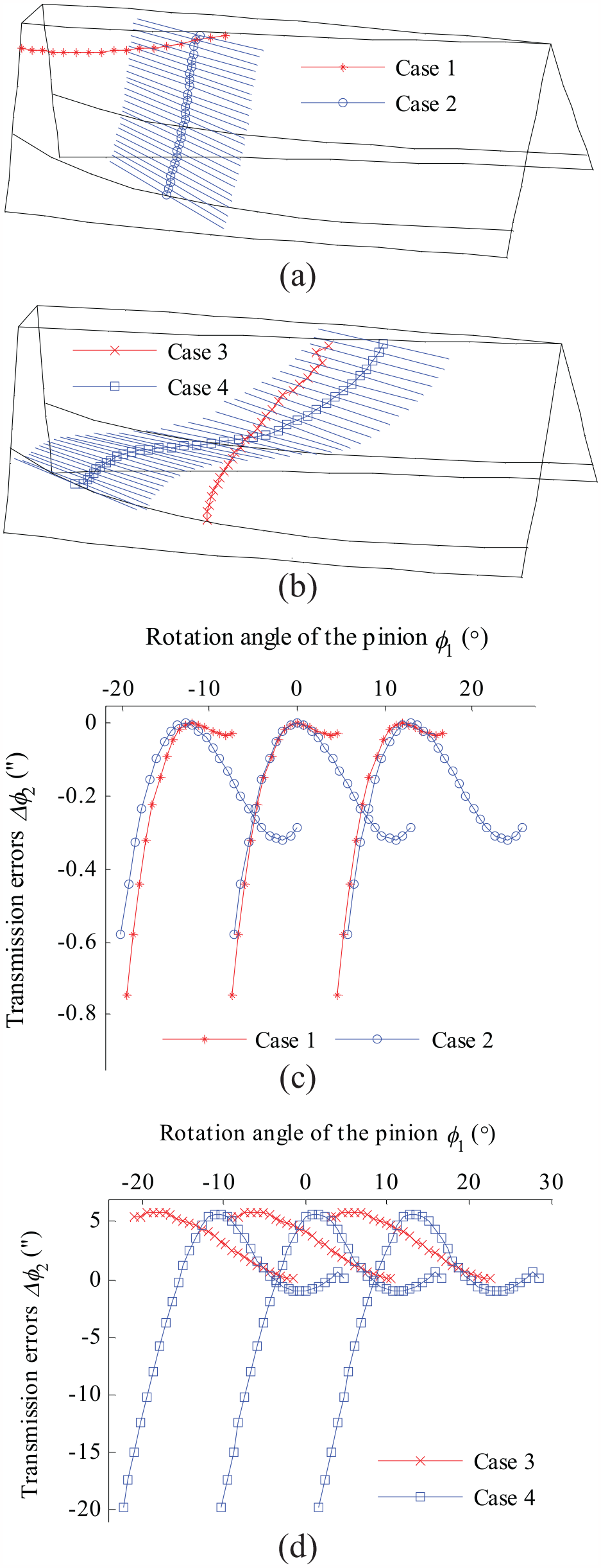
Results of contact simulation in example 1 (a) contact patern in case 1 and 2, (b) contact patern in case 3 and 4, (c) transmission errors in case 1 and 2, (d) transmission errors in case 3 and 4.
The number of teeth of the pinion in case 2 of example 1 is reduced to 28, and the contact pattern (Figure 17(a), case 2) of ΣN2 meshed with Σ1 extremely resembles that of Σ2 rolling with the same Σ1, but the transmission errors are different. The former (Figure 17(c), case 2) presents as a kind of higher-order function. At tooth replacement, the errors overlap each other, but the range is on a small scale, and the latter is a linear function equal to 0.33,34 The reason why ΣN2 can correctly roll with Σ1 is still the sufficiently small deviation (Figure 12), which is reflected by the transmission errors.
The bearing contact of case 3 of example 1 in Figure 17(b) is localized by longitudinal crowning, and the number of pinion teeth in cases 1 and 3 are the same. A comparison of the contact paths in cases 1 and 3 illustrates that the obvious localization is located at the center of the surface, reflecting that the two surfaces mainly contact the profile direction. The transmission errors in case 3, as shown in Figure 17(d), are intermittent and linear within a certain range, and this kind of transmission error may cause severe vibration and noise.33–35
Performing profile modification on the surface with longitudinal crowning in case 3 of example 1 generates a double-crowned surface ΣN2 in case 4 of example 1, in which the meshing of ΣN2 and Σ1 shows the contact in both profile and longitudinal directions, as illustrated in Figure 17(b). The contact path is a curve with a slow variation, which begins at the root toe and terminates at the top heel. The transmission errors in case 4 of example 1 (shown in Figure 17(d)) are a successive higher-order function, whose overlap at tooth replacement will lower the level of vibration and noise.33–35
Example 2 considers a face gear drive with module 3 mm and gear ratio N2/Ns = 3, the double crowned tooth surface ΣN2 of the face gear deviating from the theoretical one Σ2 generated by shaper is shown in Figure 18(a). Figure 18(b) shows the contact pattern when modified surface ΣN2 meshes with standard surface Σ1, the contact path tilts a little and locates in the center of the working surface, localized by the modification in the longitudinal direction, resembles that when the theoretical surface Σ2 meshes with crowned surface Σ1, 31 the tilt extent in Figure 18(b) depends on the value of ap. The meshing of modified surface ΣN2 and standard surface Σ1 presents a desired parabolic function of transmission errors as Figure 18(c) shown, this kind of transmission errors are benefit for adsorption of the transmission errors of the non-continuous linear function caused by misalignments.
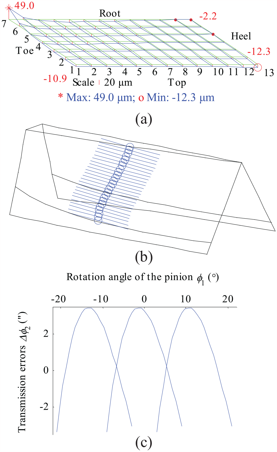
Results of contact simulation example 2 (a) sum deviation of tooth surface, (b) contact pattern, (c) transmission errors.
The mentioned results of the meshing performance of the newly defined surface ΣN2 for the face gear are sufficient to illustrate that ΣN2 is able to obtain good meshing quality by selecting appropriate parameters or performing surface modification except when the gear ratio N2/N1 < 3, in which, if the developable ruled surface is defined as the tooth flank of the face gear, it is necessary to redesign the pinion based on the conjugate method and eliminate the adverse effects caused by large surface deviation on meshing performance.
Conclusions
Based on the research performed, the following conclusions may be drawn:
A new developable ruled surface could be defined as the face gear tooth flank.
A mathematical model of the new ruled surface is presented, it is not recommended to correct the new surface, because the deviation is very small except for in the undercutting area and the manufacturing simplicity will be preserved.
The kind of straight-edged cutter is capable of generating face gears with the new ruled surface, brings high production efficiency, and the generation precision is acceptable.
When appropriate parameters are selected or surface crowning is performed, and when the gear ratio N2/N1 ≥ 3, The meshing of the new ruled surface of face gears and the involute surface of pinions is able to obtain good meshing quality. (Tip: the advantages of face gear drives are available only when the gear ratio is large, e.g. larger than 3, otherwise there is not enough bearing tooth width due to undercutting and pointing).
Footnotes
Appendix I
Declaration of conflicting interests
The author declared no potential conflicts of interest with respect to the research, authorship, and/or publication of this article.
Funding
The author disclosed receipt of the following financial support for the research, authorship, and/or publication of this article: This work was supported by Shaanxi Provincial Natural Science Foundation of China (Grant Nos. 2020JM-521).
Supplemental material
Supplemental material for this article is available online.
References
Supplementary Material
Please find the following supplemental material available below.
For Open Access articles published under a Creative Commons License, all supplemental material carries the same license as the article it is associated with.
For non-Open Access articles published, all supplemental material carries a non-exclusive license, and permission requests for re-use of supplemental material or any part of supplemental material shall be sent directly to the copyright owner as specified in the copyright notice associated with the article.