
Abstract
Performance of mechanical product is highly influenced by assembly deviation. Due to manufacturing errors, the real part surface is machined with morphology deviations, which would cause mating surface deviating from ideal position in assembly behavior, consequently leading to assembly deviation. Meanwhile, the random variation of relative position and orientation between two non-ideal parts also affects the assembly deviation. To efficiently obtain the maximum assembly deviation considering the comprehensive influence of two factors above for circumferential grinding plane, an assembly deviation calculation method based on surface deviation modeling is proposed in this paper. In this method, morphology deviations models of part surfaces are firstly established from the deviation function. The randomness of two factors are represented by a multivariate group with randomness containing deviation function coefficients and three deflected parameters. Then based on surface deviation modeling method, differential evolution algorithm is applied to search the maximum assembly deviation, which involves the construction of fitness function by implementing optimized progressive contact method and iterative operations of mutation, crossover and selection. Finally, the effectiveness of this method is illustrated by an assembly in the end.
Keywords
Introduction
In general, the function and performance of mechanical products are closely related with shape accuracy and assembly accuracy. With continuous improvement of functional requirements, the requirement for assembly accuracy has increased rapidly. As a significant influential factor of assembly accuracy, 1 assembly deviation has been paid more attention to so as to analyze the performance of product.2,3 For instance, Wang et al. 4 established an assembly deformation prediction model and a variation propagation model to predict the assembly variation of aircraft panels, which creates an analytical foundation on variation control and tolerance optimization. And Cai et al. 5 proposed a unified variation modeling method considering both rigid and compliant variations to verify the geometric and dimensional requirements of parts.
As to the expression of assembly deviation, it is a common method to use statistical characteristic quantities. Among all, the maximum assembly deviation reflects the upper and lower deviation of assembling dimensional chain in extreme cases while assembly requirements are satisfied. Therefore, it is necessary and essential to facilitate analysis on product performance, searching the maximum assembly deviation in non-ideal surface assembly.
Due to manufacturing errors, morphology deviations with randomness is unavoidable on machined surfaces and forming the non-ideal plane. When two non-ideal planes mate, morphology deviations drive the position and direction of assembled part away from the ideal state, resulting in assembly deviation. Therefore, it is the basis to study the uncertainty of morphology deviations so as to calculate assembly deviation.
To this end, relevant scholars have done lots of researches. Based on the theory of small displacement torsor (SDT), Jin et al. 6 presented a three-dimensional mathematical method of tolerance representation about conical surfaces and their joints. And Wang and Liu 7 presented a tolerance simulation for the TC2B assembling based on numerical model of TC2B and SDT model. Additionally, Qiao et al. 8 proposed the definition of curvilinear coordinate system on ideal surface and introduced the deviation dimension in the orthogonal direction to directly describe morphology deviations. These expression methods above facilitated the modeling and simulation analysis of non-ideal surface. Anwer et al. 9 discussed the concept of deviation model that is described by using systematic error and random error, and applied this model to assembly analysis. And Walter et al. 10 considered the interactions between the appearing deviations by meta-models that can be easily integrated into the functional relation. In order to systematically research the non-ideal surface and calculate the assembly deviation, Schleich and coworkers 11 proposed the concept of SMS (skin model shape) model and discretized this model with point cloud or grid data. Additionally, Zhu et al. 12 extended the SMS model and proposed an error analysis method to support the expression of assembly deviation. However, all above studies only researched the morphology deviations from the perspective of geometric, which ignored the influence of different error factors in the actual manufacturing process.
To better research the form of non-ideal surfaces, Wu et al.13,14 proposed a modeling method of non-ideal surface deviation on the perspective of manufacturing error. By establishing a deviation coordinate system, different deviation functions are constructed to represent non-ideal surface under the influence of manufacturing errors. Then the deviation of non-ideal surface is established through the combination of different deviation functions. This modeling method is consistent with actual surface influenced by manufacturing errors and simplifies the calculation of assembly deviation.
With various morphology uncertainty description method, scholars studied the influence of non-ideal surface contact state on assembly deviation, commonly first step of which is to judge contact state using algorithms. These algorithms usually contain the computation of deterministic contact points,15,16 method of constraint registration17,18 and iterative closest point algorithm (ICP). For instance, Zhu et al. 12 conducted deviation analysis and carried out assembly simulation by ICP on the basis of modeling surface deviation and judgment of surface contact points. And Schleich and Wartzack19,20 studied tolerance sensitivity based on deviation analysis of non-ideal surface, and applied it to determine the impact of geometric deviations on structural performance. Therefore, it is an effective method to calculate the assembly deviation on the basis of judging the contact state firstly.
When mating planes of two rigid parts fit, the degrees of freedom (DOFs) of part are not completely constrained. In actual assembly process, the relative position and orientation between two parts in the direction of unconstrained DOFs also have randomness in a certain range. 21 With the relative position and orientation various, assembly deviation will be different after assembly behavior while considering the morphology deviations. Therefore, the influence of relative position and orientation with randomness on assembly deviation also needs to be considered and researched.
Generally, it is necessary to obtain the maximum deviation according to the most unfavorable principle in engineering application. Aware of that the assembly deviation is influenced by the randomness of morphology deviations as well as the randomness of relative position and orientation, it is feasible to use search algorithms obtain the maximum assembly deviation. Different search algorithms such as the particle swarm optimization (PSO), 22 ICP and dynamics and genetic algorithms 23 have been applied to calculate of assembly deviation.
Compared with all the other searching algorithms such as genetic algorithm (GA) or PSO, differential evolution algorithm is more suitable contrapose the high-dimensional problems in this paper. 24 Meanwhile, using deviation modeling method proposed by Wu et al. 13 and considering the influence of relative position and orientation between two parts, search of maximum assembly deviation is transformed to a high-dimension problem with 17 parameters. In this case, differential evolution algorithm more accurate and efficient to converge the target value and has been widely applied in clustering analysis, fault detection and assembly line planning of product.25,26 Therefore, based on surface modeling method, his paper applies differential evolution algorithm to search the maximum assembly deviation. With 17 coded random parameters containing 14 deviation function coefficients and 3 random parameters in the directions of unconstrained DOFs, the assembly deviation, which is represented by three deflected parameters calculated using progressive contact method, is selected as the fitness value to construct fitness function. After the operations of mutation, crossover and selection on 17 coded parameters and iterative searching process, the maximum assembly deviation is finally obtained.
In this paper, section “Analysis of influence factors on assembly deviation and surface deviation modeling” analyzes the influence factors on assembly deviation and modeling of surface deviation, which is the basis of this contribution. Section “Differential evolution algorithm based maximum assembly deviation search” introduces the principle and process of differential evolution algorithm based method to search the maximum assembly deviation. Section “Analysis of an assembly example” gives an assembly to illustrate the effectiveness of proposed method and section “Conclusion” is the conclusion of this contribution.
Analysis of influence factors on assembly deviation and surface deviation modeling
When the mating planes of two rigid parts fit, the DOFs of part are not completely constrained. Due to manufacturing errors uncertainties, the morphology deviations with randomness occur on the part surface and cause assembly deviation. Moreover, in the directions of unconstrained DOFs, the relative position and orientation between two parts also have randomness, and directly have a vital impact on assembly deviation. To conveniently express the randomness of these two factors and facilitate calculation, it is significant and essential to establish the morphology deviation models of non-ideal surfaces. Taking circumferential grinding plane as an example, this section adopts a surface deviation modeling method from the perspective of manufacturing errors.
Impact of morphology deviations and assembly position on assembly deviation
Ideally, planar surface is flat without any deviation and it is called ideal surface. In this case, there is no assembly deviation between parts A and part B after they fit, which is shown in the Figure 1(a). Due to the effects of numerous manufacturing errors uncertainties, actual machined surface has random morphology deviations so that is called non-ideal surface. Because of morphology deviations, the points on non-ideal surface would deviate from ideal position, leading to the assembly deviation in the directions of constrained DOFs. Meanwhile, with morphology deviations uncertainty, the position of contact points would change so that assembly deviation also has uncertainty, which is shown in Figure 1(b) and (c). In order to facilitate obtaining the assembly deviation, the global coordinate system and the local coordinate system are established, both of which belong to Cartesian coordinate systems. Firstly, the global coordinate system S is defined with its X-Y plane located on the ideal plane of part B. During assembly process, part B is fixed so that the position and orientation of it is also unchangeable. And the position and angle of two parts as well as their relation could be described by the coordinate difference in S. Then two local coordinate systems respectively named SA and SB are established on corresponding parts. The X-Y planes of SA and SB are coincident with the ideal planes of corresponding parts with the origins in geometric centers. Due that relative positions between local coordinate systems and corresponding ideal surfaces are fixed, the position and orientation of part A relative to part B can be represented by the position and orientation of the SA in the S after assembly behavior.
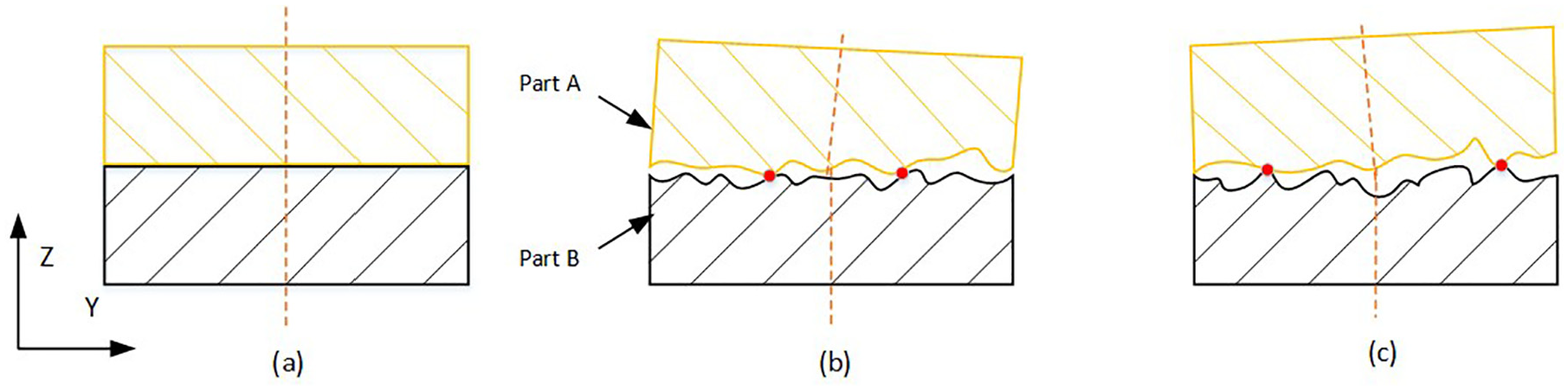
Schematic diagram of the fitting for non-ideal surfaces with random morphology deviations: (a) The fitting of ideal surfaces, and (b) (c) The fitting of non-ideal surfaces with random morphology deviation.
When two mating planes fit together, the position and orientation relation between two parts contains the displacement along Z-axis and the angles around X-axis and Y-axis. Therefore, assembly deviation could be represented by three deflected parameters in the directions of constrained DOFs. Meanwhile, there are other three unconstrained DOFs including the translation along X-axis and Y-axis and the rotation around Z-axis. For the actual assembly behavior, the relative position and orientation between two parts in the directions of unconstrained DOFs has randomness in a certain range and can be described by three parameters (tx, ty, tz). From Figure 2, it is illustrated that with different relative position and orientation, assembly deviation therewith is different.
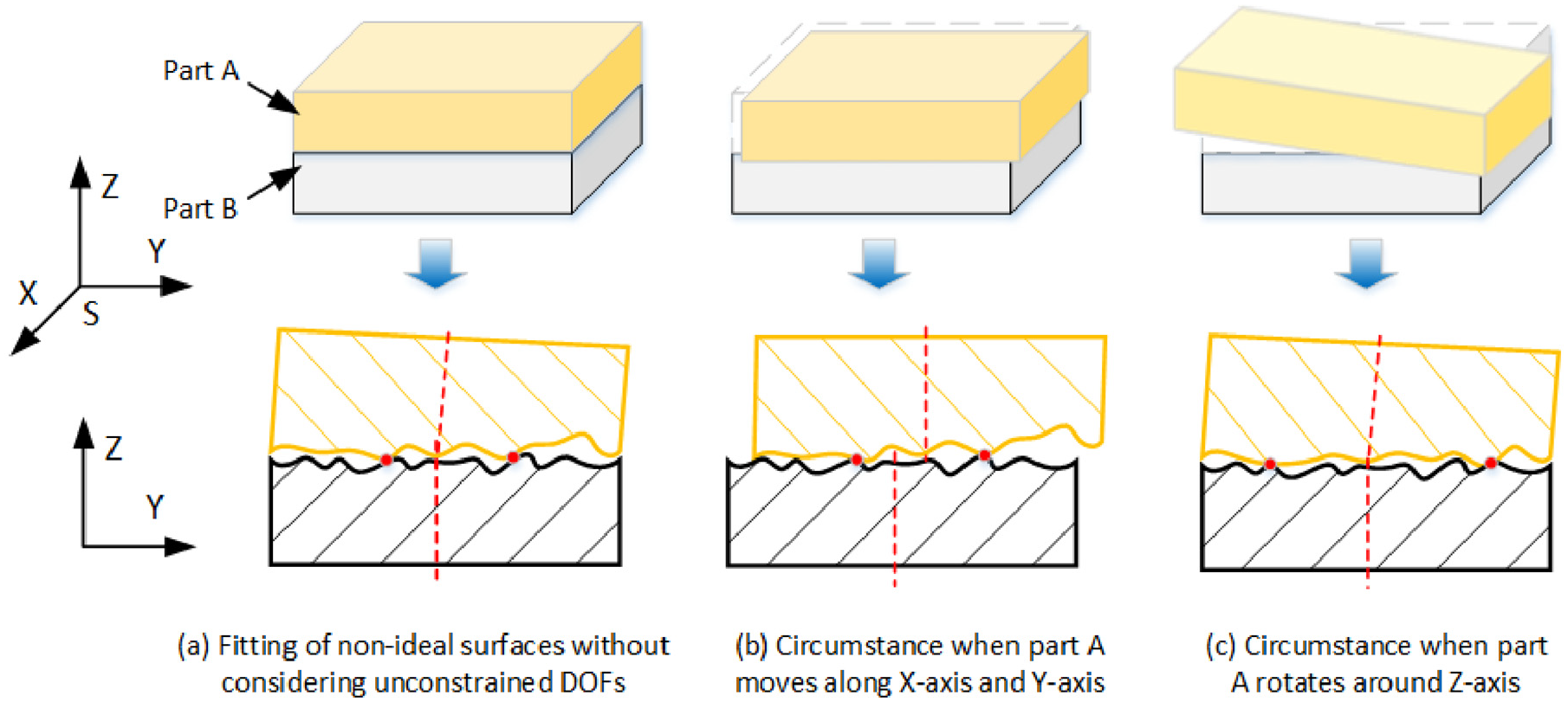
Schematic diagram of fitting with random relative position and orientation between two parts in the directions of unconstrained DOFs.
To sum up, both of morphology deviations and relative position and orientation between parts have randomness and have an impact on the assembly deviation. Therefore, it is essential to consider the comprehensive influence of these two factors to obtain the maximum assembly deviation.
Surface deviation modeling for circumferential grinding plane
Before predicting the contact status of assembly, it is a common and necessary step to establish the surface deviation models. While part surface is composed of point clouds, due to the manufacturing errors, the deviations of points on non-ideal surface have randomness as well as have correlation with adjacent points. Therefore, it is an effective and practical method to establish surface deviation model from the perspective of manufacturing errors.
In this paper, the deviation modeling method proposed by Wu et al. 13 is applied to facilitate assembly deviation calculation. In this method, besides global and local coordinate system, the deviation coordinate system (q1, q2, δ) should be established to define the morphology deviations of surface points. It is established by introducing deviation dimension in the direction orthogonal to two-dimensional curvilinear coordinate system (q1, q2), where curvilinear coordinate q1 represents the position of the machining track in the feed direction, q2 represents the position of characteristic points on machining track in the main motion direction and δ represents the points deviation of actual machining surface relative to ideal surface.
Taking circumferential grinding plane as an example, q1 and q2 are two orthogonal linear coordinate axes so that the deviation coordinate system belongs to Cartesian coordinate system. In assembly behavior, deviation coordinate systems of two mating planes named DA and DB are set to coincide with their corresponding local coordinate systems to facilitate the calculation. Three types of coordinate systems in this paper are shown in Figure 3. In DA and DB, the morphology deviations of non-ideal surfaces are described by the function δ = Δ(q1, q2) so that the function value of each point represents its point deviation from ideal position. Therefore, the actual machined surface could be expressed using the superposition of deviation function and value of ideal surface. Moreover, the basic plane q1Oq2 of deviation coordinate system is just the ideal part plane, meaning that value of the ideal surface is always 0. Therefore, the deviation δ = Δ(q1, q2) function directly represents the actual machining surface.
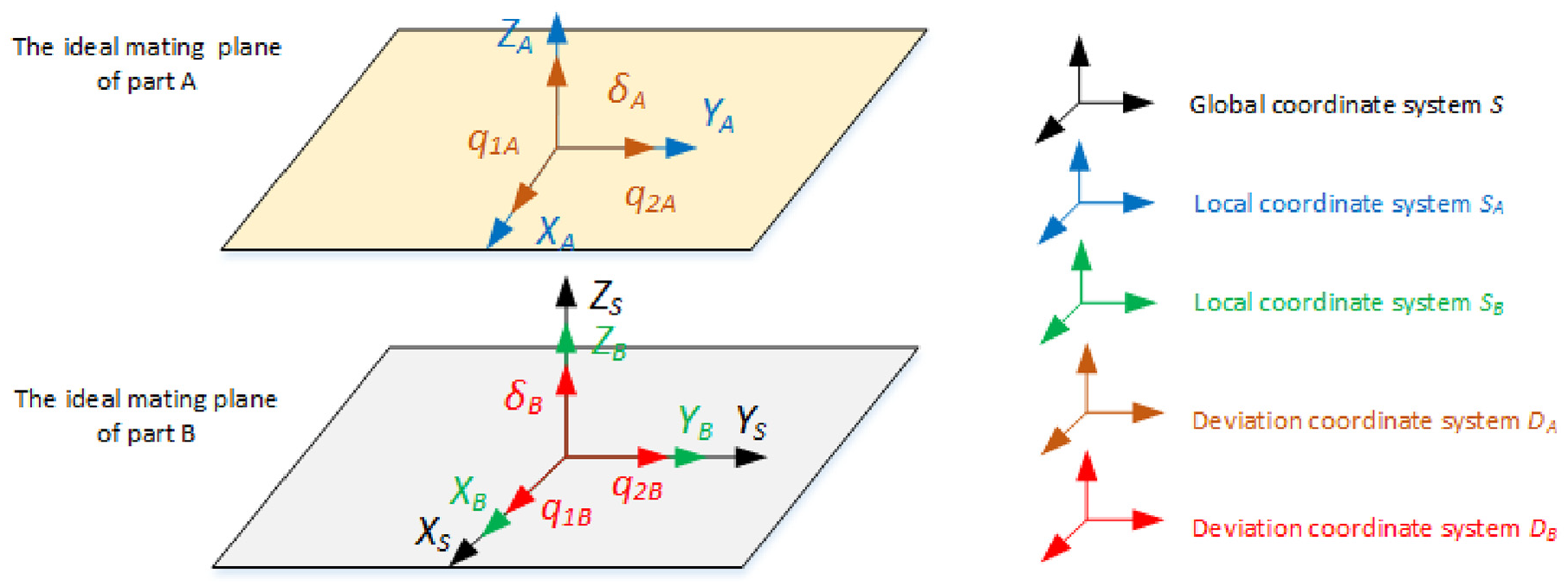
Position of three types of coordinate systems on two parts.
According to the experiment and research by Qiao and Wu, the equation that expresses machined surface influenced by one manufacturing error factor is defined as simple function δ(D, q1, q2) such as polynomial functions, trigonometric functions and exponential functions etc., where D represents the coefficients set of deviation function containing (D1, D2, D3) below. Since actual machined surface is influenced by numerous manufacturing errors, the final surface equation is the superposition of numerous simple functions.
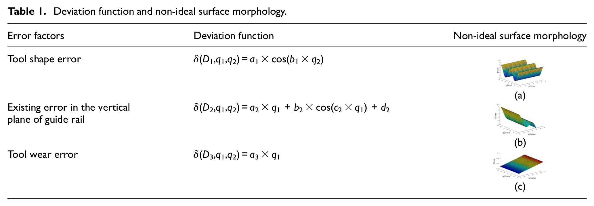
Taking circumferential grinding plane as an example, the morphology deviations are influenced by tool shape error, existing error in the vertical plane of guide rail and tool wear error. Among them, taking account of the morphology deviations caused by tool shape error, the deviation function is trigonometric function expressed by following equation:

Taking account of the morphology deviations caused by existing error in the vertical plane of guide rail, the deviation function is composed of linear function and trigonometric function expressed by following equation:

Taking account of the morphology deviations caused by tool wear error, the deviation function is linear function expressed by following equation:

Among them, Di(i = 1, 2, 3) represents the coefficients set of deviation function caused by the ith manufacturing error factor, and (a1, b1, a2, b2, c2, d2, a3) represents the coefficients set of deviation function D for circumferential grinding plane.
Therefore, since that morphology deviations uncertainty comes from the uncertainty of manufacturing errors, it can be directly described by the randomness of deviation function coefficients. For the circumferential grinding plane in this paper, the morphology deviations uncertainty of one surface is expressed by seven deviation function coefficients (a1, b1, a2, b2, c2, d2, a3).
According to the superposition principle of deviations, surface deviation models corresponding to each manufacturing error and the synthesized surface deviation model are shown in Figure 4.
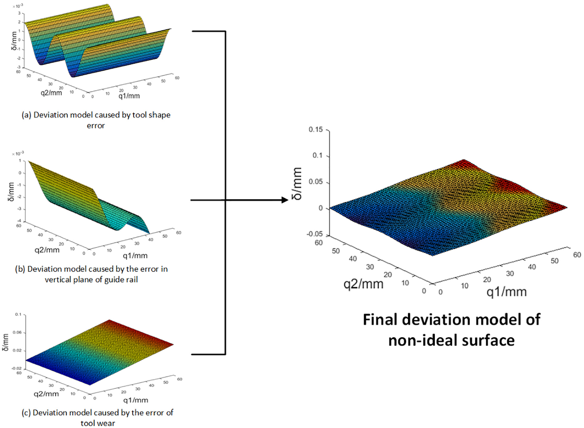
Schematic diagram of non-ideal surface deviation modeling.
The non-ideal surface deviation modeling from the perspective of manufacturing errors not only conformed to the actual manufacturing process, but also conveniently described the morphology deviations uncertainty through the randomness of deviation function coefficients, which facilitates the generation of non-ideal surface samples and later assembly deviation calculation.
Differential evolution algorithm based maximum assembly deviation search
From the last section, the assembly deviation depends on two factors including morphology deviations and the relative position and orientation between two parts, randomness of which is described by numerous parameters in corresponding domains. Therefore, selected algorithm should meet the principle of and accurately effectively searching the maximum assembly deviation in high-dimension problem. In this paper, a differential evolution algorithm based method is applied, which belongs to evolutionary algorithm essentially and it unifies parameters into a multivariate group to contain all the numerous parameters information. Then with the assembly deviation calculated by optimized progressive contact method as fitness value, the fitness function is constructed. Through the iterative operations of mutation, crossover and selection, better individuals will be retained so that the maximum assembly deviation will be found out.
Search target of differential evolution algorithm
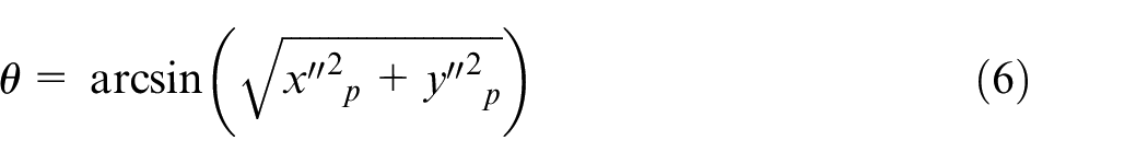
Since that part B is assumed to be fixed in assembly process, the assembly deviation could be regarded as the transformation of SA relative to S from initial position to final position, which can be divided into the displacement process along the Z-axis of S and the rotation process around the origin of SA. In the displacement process, since the pointing deviation along the Z-axis of SA and the displacements along the X-axis and Y-axis are quite small after assembly, the origin of SA could be thought to only move in the Z-axis direction of S. Therefore, the displacement is expressed by the distance tZ between origin of SA and origin of S in Z-axis direction. In the rotation process, the angle deviation between SA and S is expressed by nutation angle θ and precession angle ψ of Euler angles, which is shown in Figure 5.
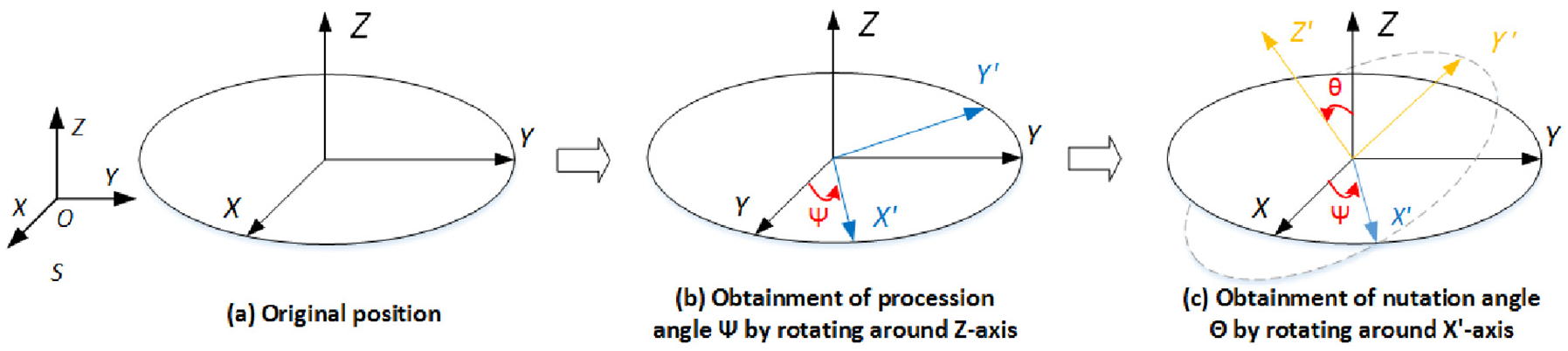
Schematic diagram to represent the angle deviation using Euler angle.
Therefore, the assembly deviation is represented by three deflected parameters including tz, θ, and ψ.
Coding by real numbers
In the differential evolution algorithm, coding is the first step to unify all information into a multivariate group and generate initial population. From last section, the randomness of morphology deviations is described through the randomness of deviation function coefficients, and the randomness of relative position and orientation between two parts is described through the randomness of three parameters (tZ, θ, ψ) in the directions of unconstrained DOFs. In circumferential grinding plane, the final deviation function of each plane contains seven coefficients (a1, b1, a2, b2, c2, d2, a3). Therefore, 17 bits of real numbers are set in this paper, where 1–7 bits respectively correspond to the deviation function coefficients of part A, 8–14 bits respectively correspond to the deviation function coefficients of part B and 15–17 bits respectively correspond to three random parameters (tZ, θ, ψ). The schematic diagram of coding by real numbers is shown in Figure 6.
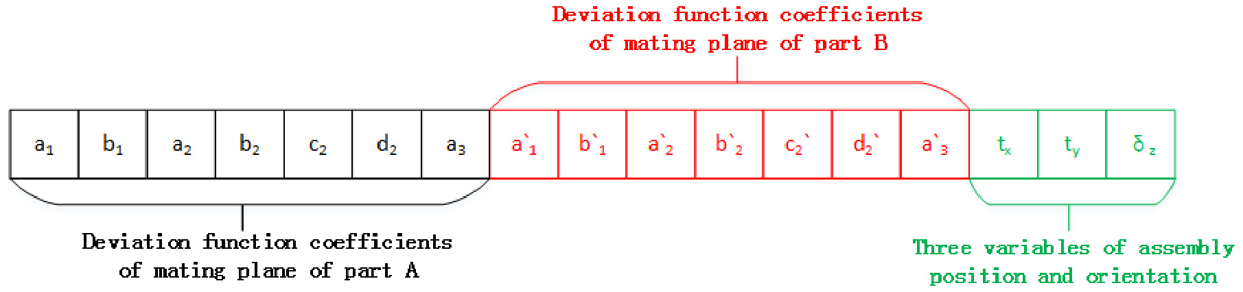
Schematic diagram of coding by real numbers.
A multivariate group is composed of these 17 bits parameters and to randomize them essentially, it is assumed that the distribution of each parameter conforms to the normal distribution with its own mean µ and variance σ. Before searching the existence domains of multivariate group, the domain ranges of each number need to be determined. According to the principle of 3µ, the probability that value corresponding to normal distribution is within the range of (µ − 3σ, µ + 3σ) is 0.9973, which means this circumstance is regarded as the impossible event. Therefore, the range of each parameter in the multivariate group is (µi − 3σi, µi + 3σi), where i represents the sequence of parameter in the multivariate group.
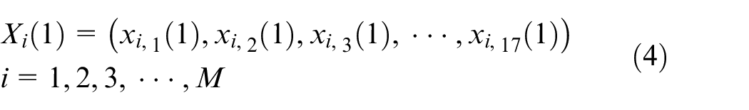
A multivariate group represents a pair of planes to be fitted and it is regarded as an individual in differential evolution algorithm. Therefore, the initial population with a total of M individuals is randomly generated, in which the first generation is expressed as following equation:
Search process for maximum assembly deviation
After the initial population is generated by coding of real numbers, searching process is divided into the construction of fitness function and the operations of mutation, crossover and selection according to the routine of differential evolution algorithm. From the subsection “Search target of differential evolution algorithm,” the assembly deviation is expressed by three deflected parameters including tz, θ, and ψ. In this paper, these three deflected parameters are calculated through the optimized progressive contact method and one of them is taken as the fitness value to construct the fitness function. Then contrapose the multivariate group, individual with highest fitness, also the maximum assembly deviation, will be found out through the iterative operations of mutation, crossover, and selection.
In the progressive contact method, the calculation process is regarded as the transformation process from initial state to final state, which essentially determines three contact points between two planes one by one. In this paper, besides morphology deviations, the relative position and orientation between two parts should also be taken into consideration. Under this circumstance, firstly only considering the morphology deviations uncertainty, two deviation coordinate systems are coincident at the beginning so that the points on two planes have one-to-one correspondence in the Z-axis direction of S, which is shown in Figure 7(a). Given that this method is actually the process of determining three contact points, distance between the points on two parts in S is implemented to judge the contact state in this paper. When this distance becomes zero, it means that two non-ideal plane contact with each other. Moreover, since the coordinates of points are firstly represented in the DA and DB, it is essential to convert them into the coordinates of S firstly to facilitate later calculation. In the whole process of progressive contact method, with part B fixed, two planes are firstly separated at a distance and first contact point is determined by moving the part A in the Z-axis direction of S. Then second contact point is determined by rotating part A around the first contact point. Finally third contact points is determined by rotating part A around the axis connecting the first and second contact points, as shown in Figure 7.
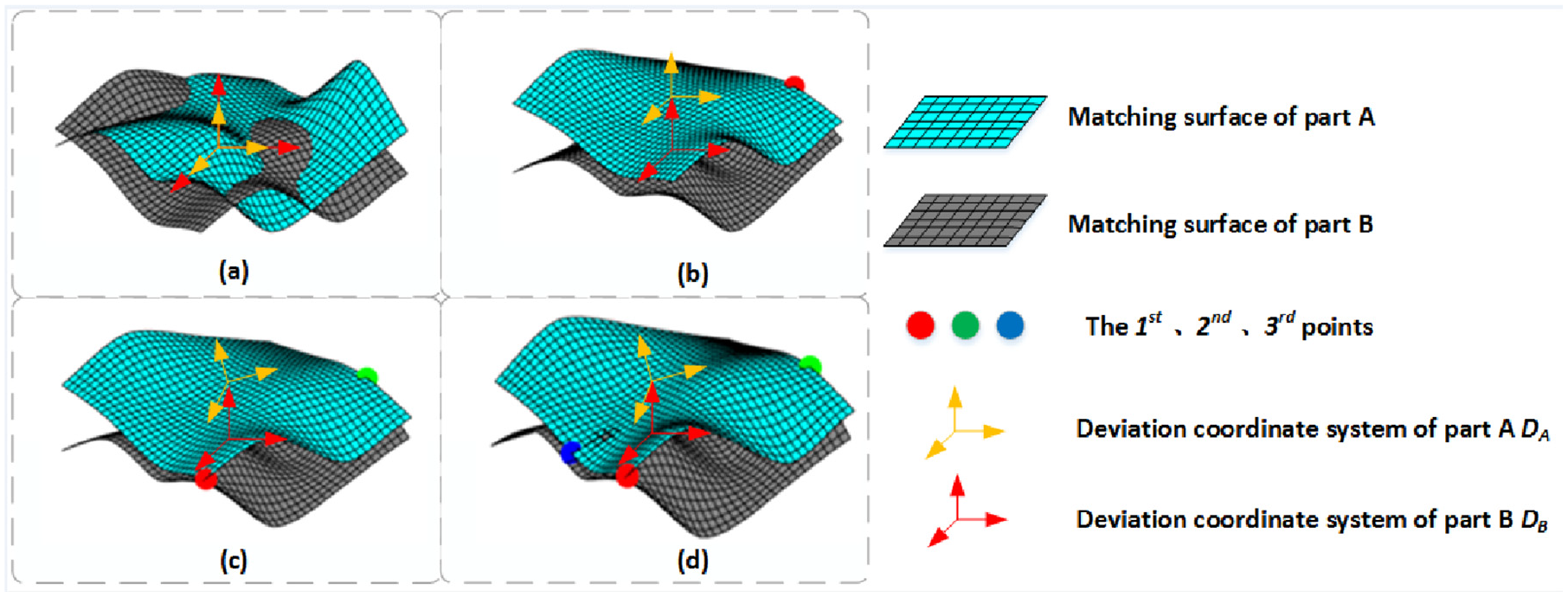
Schematic diagram of progressive contact method: (a) Original state, (b)The first contact point is identified, (c)The second contact point is identified, and (d)The third contact point is identified.
Based on the process above, the randomness of relative position and orientation should be taken into consideration. At this circumstance, two deviation coordinate systems do not coincide in the initial state, leading that points on two planes do not correspond in the Z-axis direction of S. Therefore, points on two planes are paired up anew by projecting points on part A to the mating plane on part B along the Z-axis direction to obtain the projection points. Then find the closest point on part B to the projection point, which is just its corresponding point. This flow is shown in Figure 8.
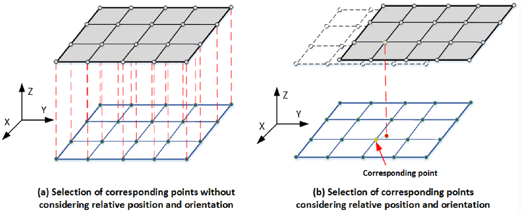
Schematic diagram of searching corresponding points.
Through this optimized progressive contact method, the coordinates of three contact points in S are obtained. Then, from the subsection of “Search target of differential evolution algorithm,” the assembly process can be equivalently transformed into the displacement process and rotation process shown in Figure 9. To facilitate calculation, suppose that there is a point p directly located above the mating plane in the S. Its initial coordinate is (tx, ty, 1) and it is always located on the Z-axis of SA. Therefore, the point p coordinate will change with equivalent displacement process and rotation process. Through the process of optimized progressive contact method, after displacement process the coordinate is

This solving process of assembly deviation is shown in Figure 9.
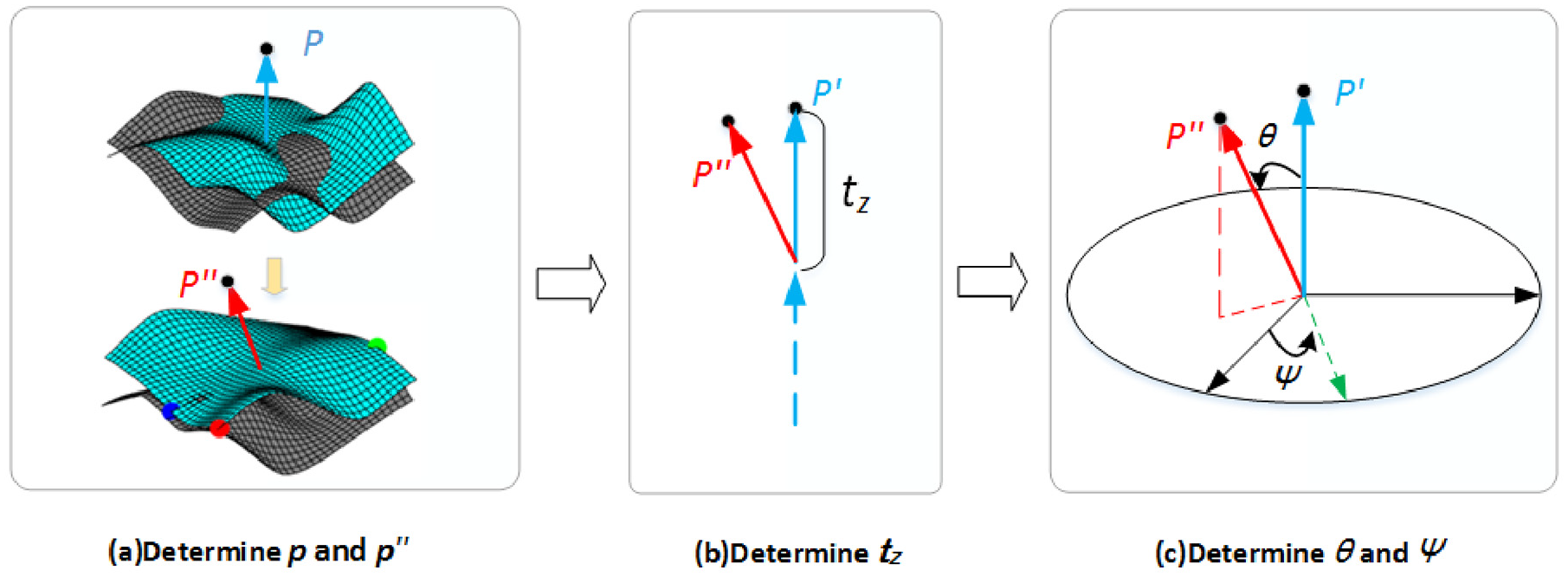
Schematic diagram for calculation process of assembly deviation.
Among three deflected parameters including tz, θ, and ψ used to represent assembly deviation, someone is selected as the fitness value according to different search target.
If the displacement deviation tz is selected as target, fitness function is expressed as following equation:

If the nutation angle θ is selected as target, fitness function is expressed as following equation:

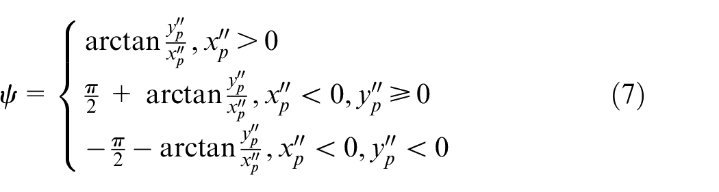
If the precession angle ψ is selected as target, fitness function is expressed as following equation:

After the construction of fitness function, the iterative operations of mutation, crossover and selection need to be conducted to obtain the maximum assembly deviation. In the gth iteration, the individual to mutate is the p1th individual Xp1(g), then three individuals Xp1(g), Xp2(g), Xp3(g) are randomly selected to generate the mutant individual, in which P1 ≠ P2 ≠ P3.
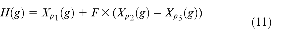
Therein, F is the scaling factor.
Crossover operation is carried out on the generated mutant individual H′ and original individual Xb. In cross operation, each digit has a certain probability of crossing and the new individual V is obtained by the crossover:
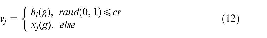
In the equation (12), cr ∈ [0, 1] is the probability of crossover, vj is the jth value of V, hj is the jth value of H′ and xj is the jth value of Xb.
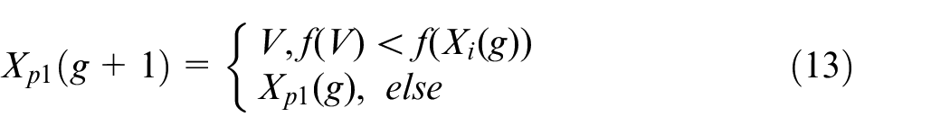
In selection operation, the mutated and crossed individuals are compared with Xb to retain the better individuals:
In order to avoid the precocious phenomenon in the search process, the adaptability of mutation operator F need to be increased:
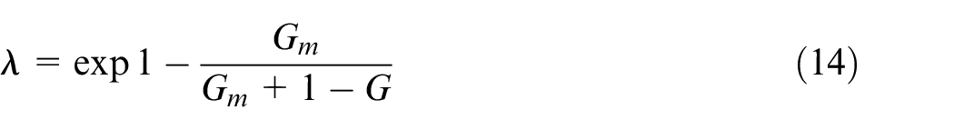

Therein, F0 is a constant number, Gm is the maximum evolutionary generation while G is the current evolutionary generation.
After the operations of mutation, crossover and selection, retained individual with the largest fitness value need to be judged whether it satisfies the termination condition. If it satisfies, this algorithm could be terminated. If not, continue the operations above and keep iterating until the termination condition is satisfied. Therefore, through iterative searching, the maximum assembly deviation is obtained.
Analysis of an assembly example
Three deflected parameters including tz, θ, and ψ used to represent the assembly deviation from the last section have been widely applied in the industrial manufacturing field. For instance, the maximum tz can be used to analyze the upper and lower deviations of the assembling dimensional chain. And the maximum nutation angle θ can be used to analyze the transmission ratio of equipment or transmission system with nutation drive, which is widely applied in winding machine, nutation gear system and nutation grinding. Take a typical injection mould component widely applied in pump valve as an instance in Figure 10, the length and width of the mating plane are both 156 mm. In order to satisfy the requirement of machining accuracy, the parts are usually machined through circumferential grinding plane, which is influenced by manufacturing errors. Moreover, the maximum assembly deviation produced in assembly process need to be calculated to facilitate improving the assembly accuracy.
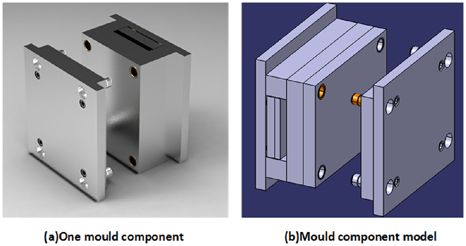
Schematic diagram of the injection mould component.
According to the procedures of calculating assembly deviation from the content above, surface deviation model is firstly established from the perspective of manufacturing errors. Then, the search target is selected according to the actual industrial requirement. In the design stage for instance, if the assembly deviation passing through the dimension chain of parts assembly should compare with the upper and lower deviations to judge whether it meets the requirement, the displacement deviation tz will be selected as the target.
Table 1 shows the deviation function corresponding to manufacturing error factors including tool shape error, existing error in the vertical plane of guide rail and tool wear error of circumferential grinding plane. And Table 2 (in this Table 1, figure (a) is just the Figure 4(a), figure (b) is just the Figure 4(b) and figure (c) is just the Figure 4(c)) shows the range of the deviation function coefficients and the domain of relative position and orientation between two parts.
Deviation function and non-ideal surface morphology.
Deviation function coefficients and variation range of position and orientation.
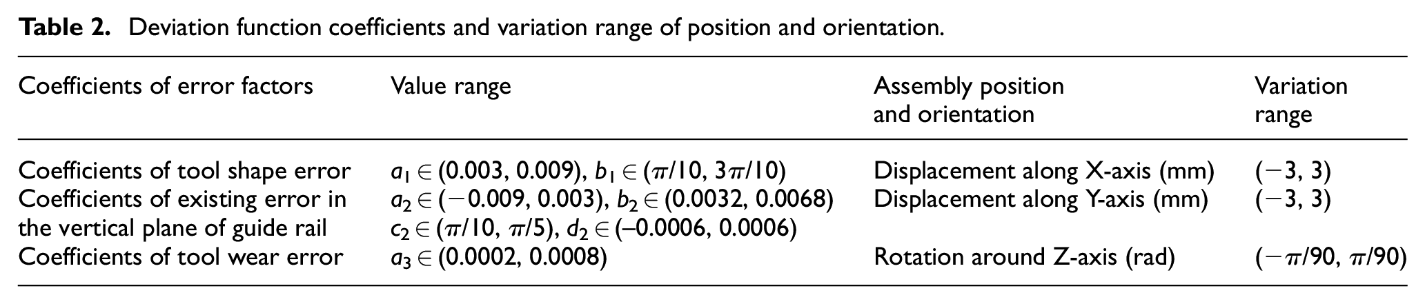
Moreover, since there are four holes with the radius of 2.5 mm in each mating planes, the surface deviation modeling should considered the influence of hole so that the point cloud of the hole is eliminated in the calculation process. Within the domain given in Table 1, differential evolution algorithm is used to search the maximum assembly deviation.
As to the parameters in differential evolution algorithm, it is assumed that the total number of initial population is M = 100, the scaling factor in mutation operation is Fµ = 0.9, Fl = 0.1 and the crossing probability in crossover operation is cr = 0.5. The terminal condition is set that the maximum times of iteration is Nmax = 500 or the fitness value of the best individual does not change through 100 times of iteration.
After calculation, when the displacement deviation tz is selected as target, the final maximum value is ft = 0.0956 mm. When the nutation angle θ is selected as target, the maximum value is fθ = 0.000542 rad. When the precession angle µ is selected as target, the maximum value is fµ = πrad. When it is necessary to judge whether the result satisfies the actual assembly requirements, transfer the maximum value ft = 0.0956 mm through the assembly size chain and compare the deviation with requirements of the upper and lower deviations in the actual production process.
Conclusion
In this contribution, an assembly deviation calculation method based on surface deviation modeling for circumferential plane is proposed. This method considers the comprehensive influence of randomness of morphology deviations as well as the randomness of relative position and orientation between two parts, and effectively searched the maximum assembly deviation.
Using non-ideal surface deviation modeling method from the perspective of manufacturing errors, randomness of two factors in this paper is directly described through he randomness of deviation function coefficients, which facilitates the generation of non-ideal surface samples and later calculation.
The displacement deviation and angle deviation obtained by optimized progressive contact method directly describes the assembly process, and the angle deviation represented by the nutation angle and precession angle of Euler angle facilitates the calculation.
Using the randomness of the deviation function coefficients and random variation of three random parameters, the calculation problem of assembly deviation is transformed to a high-dimension problem containing 17 parameters. The differential evolutionary algorithm is feasible solve this high-dimensional problem and the result of an assembly example verified effectiveness of this method.
Footnotes
Declaration of conflicting interests
The author(s) declared no potential conflicts of interest with respect to the research, authorship, and/or publication of this article.
Funding
The author(s) disclosed receipt of the following financial support for the research, authorship, and/or publication of this article: This work was supported by the National Science Foundation of China (Grant 51575031).