
Abstract
A new method is presented for advanced manufacture of hypoid gears on numerical controlled machine tool. The tool geometry and machine tool settings are determined to introduce the optimal tooth modifications into the teeth of hypoid gears. The goal is to reduce the maximum tooth contact stresses, angular displacement error of the driven gear, and energy losses in the oil film existing between tooth surfaces. The calculation is based on the optimal variation of machine tool settings on the classical machine tool for hypoid gear manufacture. The novelty of the method is that during the machining process of teeth surfaces, the variation of machine tool settings on the cradle-type hypoid generator is conducted by polynomial functions of fifth-order. By an algorithm, this variation of machine tool settings is transferred to the numerical controlled machine tool for hypoid gear manufacture (hypoid generator). The obtained results have shown that by applying the optimal manufacture process, considerable reductions in tooth contact stresses and angular displacement errors of the driven gear, and a moderate reduction in energy losses were obtained. Therefore, by applying this new method in practice, advanced manufacture of hypoid gears on CNC hypoid generator is made possible, resulting improved operating characteristics of the hypoid gear pair.
Introduction
Hypoid gear drives are widely used to transfer mechanical power between the intersecting axes in transmission elements in automotive, aircraft, and ship industries. The optimization of tooth flank topography is an increasingly strategic stage in hypoid and spiral bevel gear design process due to increasing demand of more load carrying capacity and less vibration and noise. The problem to solve is how to translate the optimized tooth surface topography into the corresponding machine tool setting variation. Accompanied by rapid development and application of computer numerically controlled (CNC) hypoid generating machines, design and manufacturing of spiral bevel, and hypoid gears has been significantly advanced and has become a highly sophisticated process that relies on the employment of computerized tools and methodologies.
In the last decades numerous research works were published on the optimization of design and manufacture of spiral bevel and hypoid gears. Some of them are as follows:
Cao et al. 1 presented a new method for the determination of machine tool-settings for the manufacture of the pinion of spiral bevel gears. Gonzalez-Perez et al. 2 presented a method for analytical determination of basic machine-tool settings for generation of spiral bevel gears from blank data. Gabiccini et al. 3 investigated the transfer of motions from the cradle-type to the CNC machine. Li et al. 4 proposed a new method for the manufacture of spherical involute gears. A method for processing the pinion of large-sized bevel gears on six-axis machine tool is presented by Kawasaki et al. 5 Zhang et al. 6 determined the relation among the motions on the six-axis machine for the manufacture of hypoid gears. Mo and Zhang 7 proposed a method for the manufacture of spiral bevel gears verified by gear cutting and contact experiments. A method to adjust the machine-tool settings for the manufacture of hypoid gears, with generated and nongenerated tooth surfaces, was presented by Perez et al. 8 Chen and Wasif 9 derived a new calculation method for machine tool settings for the manufacture of hypoid gears on CNC machines. A new method for the calculation of machine-tool settings for the manufacture of spiral bevel and hypoid gears was proposed by Zhang and Yan. 10 Ding et al. 11 presented a method for the variation of machine tool settings to improve the conditions of tooth contact in spiral bevel and hypoid gears. A new method was derived by Ding et al. 12 for high-performance manufacture of spiral bevel and hypoid gears. The same author 13 proposed multi-objective optimized machine tool settings to improve the tooth contact in spiral bevel gears. Ding and Tang 14 in their paper presented a six sigma multi-objective optimization method for the manufacture of hypoid gears. By Hu et al. 15 the machine setting for the manufacture of spiral bevel gears was optimized to improve meshing characteristics. Zhou et al. 16 developed a method to determine the machine tool settings to eliminate the geometric error in spiral bevel and hypoid gears. Wasif and Chen 17 developed an accurate cutting system for face milling hypoid gears. A CAD model of a head-cutter was presented by Wasif et al. 18 Guo et al. 19 introduced a special cutter blade profile to improve the load and stress distribution in spiral bevel gears. The tilt cutting method was used by Jiang et al. 20 to speed up the manufacture of internal bevel gears. Zhou et al. 21 developed the new five-axis flank milling of spiral bevel gears. The same author 22 proposed a method of NC programming to improve the manufacture of spiral bevel or hypoid gears. To reduce the running noise and vibration of spiral bevel gears, Mu et al. 23 proposed a new method for the design of spiral bevel gears with reduced noise and vibration. To avoid tooth edge contact caused by misalignment of the gear pair or heavy load, Mu et al. 24 corrected the cutter blade profile in the process of spiral bevel gears. Wang et al. 25 focused on the evaluation of the best fingertip shape for the manufacture of spiral bevel gears. Based on the face-milling cutting method and non-circular gear meshing theory, Zheng et al. 26 investigated the generation of curvilinear non-circular cylindrical gears and the corresponding manufacture process. Deng et al. 27 proposed a manufacturing model for spiral bevel gears by combining the manufacture technology with network, information, and management. Tan et al. 28 tried to manufacture tooth surfaces of spiral bevel gears by disc milling process and pure-rolling contact. A data-driven optimization model was proposed by Shao et al. 29 to improve competitiveness of hypoid gear product development facing with economic globalization. Yong et al. 30 optimized the feed in format cutting of cycloidal bevel gears. The purpose of the study made by Wang et al. 31 was to manufacture a split equal-base circle bevel gear. Han et al. 32 proposed a tooth surface contour error modeling method and an adaptive electronic gearbox cross-coupling controller for internal gearing power honing. A new shaving method for double crowning that has no natural twist in the tooth flanks on the work gear surfaces is proposed by Hsu et al., 33 using a variable pressure angle shaving cutter in a parallel gear shaving process. Gonzalez-Perez and Fuentes-Aznar 34 proposed an analytical method for derivation of basic machine-tool settings that allows the conjugated action in face-hobbed spiral bevel and hypoid gear drives wherein the gear is not generated. Liang et al. 35 investigated the effects of three different types of blade sections including linear, circular, and polynomial on mesh characteristics for face-hobbed hypoid gears. The face-gear member of the gear pair is generated based on the errors of alignment to be compensated by adjusting the position of the shaper cutter to replicate the relative position of the pinion in misaligned condition in the paper published by Guo and Fuentes-Aznar. 36 Zhang et al. 37 proposed a tooth grinding method using large diameter conical grinding wheel for formate face-hobbed hypoid gears. In order to improve processing accuracy and efficiency of tooth crest chamfering of spiral bevel gear, a new method was developed by Wei et al. 38 Computerized approach for the design and generation of face-milled non-generated hypoid gears with low shaft angle is presented by Liu et al. 39
By analyzing the above referenced papers the following summarization can be made:
In numerous papers, the machine tool-settings for pinion generation are determined in order to satisfy the prescribed tooth blank offset.1,10,12,29,33,34
Another aspect for the determination of machine-tool settings is to improve meshing tooth contact performance.2,11,13,15,35
In papers17–19 the cutter geometry is optimized to improve the performance characteristics of spiral bevel and hypoid gears.
In the case of large size gears, or to reduce the high cost for manufacture of small group of spiral bevel or hypoid gears on special hypoid generators, universal five-axis computer numerical control (CNC) machines are used 21 and non-generated shaping methods are applied to process the tooth surfaces.5,21
Recently, special CNC hypoid generators are used to manufacture spiral bevel and hypoid gears.6,9,22,26,30
Only a few papers can be found on multi-objective optimization of spiral bevel and hypoid gears.13–15 In these studies, the optimized machine tool settings are constant during the machining process.
It can be concluded that there has not been published an overall model for optimized manufacture of hypoid gears on CNC machine.
Novelty of the paper
To fill the above-mentioned gap, a new method is developed for the optimization of the manufacture process of hypoid gears on a numerical controlled machine tool (hypoid generator). The optimal tooth surface modifications are introduced by the variation of head-cutter geometry and machine tool settings. The goal of these tooth surface modifications is to reduce maximum tooth contact pressure, angular displacement error of the driven gear, and energy losses in the oil film existing between the tooth surfaces. The optimization of the manufacturing process is based on the variation of machine tool settings during the manufacture process on the cradle-type machine tool for the manufacture of spiral bevel and hypoid gears. The variation of machine tool settings is conducted by polynomial functions of fifth-order. The new numerical controlled machine tools have made it possible to perform varying correction motions during the cutting process. An algorithm is developed for the conduction of motions on the numerical controlled machine tool, using the optimized machine tool variations on the cradle-type machine. For the determination of maximum tooth contact pressure and angular displacement error of the driven gear the loaded tooth contact analysis (LTCA), 40 should be performed. The determination of energy losses in the gear pair is based on the thermal mixed elastohydrodynamic analysis of lubrication. 41 Both methods are developed by the author of this paper. Based on this theoretical background, the corresponding computer program was developed.
By applying this computer program, a face-milled hypoid gear pair was investigated. The obtained results have shown that by the optimization of the manufacture process, significant reductions in the maximum tooth contact pressure and in the angular displacement error of the driven gear can be achieved. The reduction of the energy losses in the gear mesh is moderate.
The novelty of the new method is that during the machining process of teeth surfaces, the variation of machine tool settings on the cradle-type hypoid generator is conducted by optimized polynomial functions of fifth-order, and this variation of machine tool settings is transferred by a new algorithm to the numerical controlled machine tool for hypoid gear manufacture (hypoid generator).
The manuscript is divided into the following sections: The manufacture of hypoid gears on a cradle-type generator is introduced in Section 2. The multi-objective optimization model with the variation functions for machine tool settings is presented in Section 3. In Section 4 the manufacture of hypoid gears on a CNC hypoid generator and the algorithm for the transfer of motions from the cradle-tape to the CNC generator are developed. The computed results are presented in Section 5.
Manufacture hypoid gears on cradle-type generator
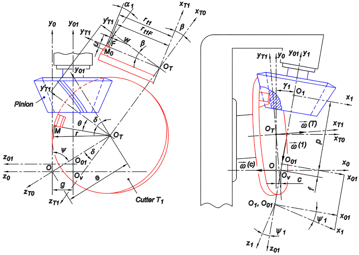
The pinion is generated and the gear is non-generated in the considered gear pair. To improve the meshing characteristics of the gear pair modifications are introduced into the tooth surface of the pinion. By the introduction of these modifications the theoretical line contact of tooth surfaces changes into point contact. The modifications are introduced by the appropriate variation in machine tool settings and the geometry of the head-cutter. The machine tool settings are defined in Figure 1: sliding base setting (c), basic radial (e), basic machine center to back increment (f), basic offset (g), tilt angle (


where
Manufacture of pinion teeth.
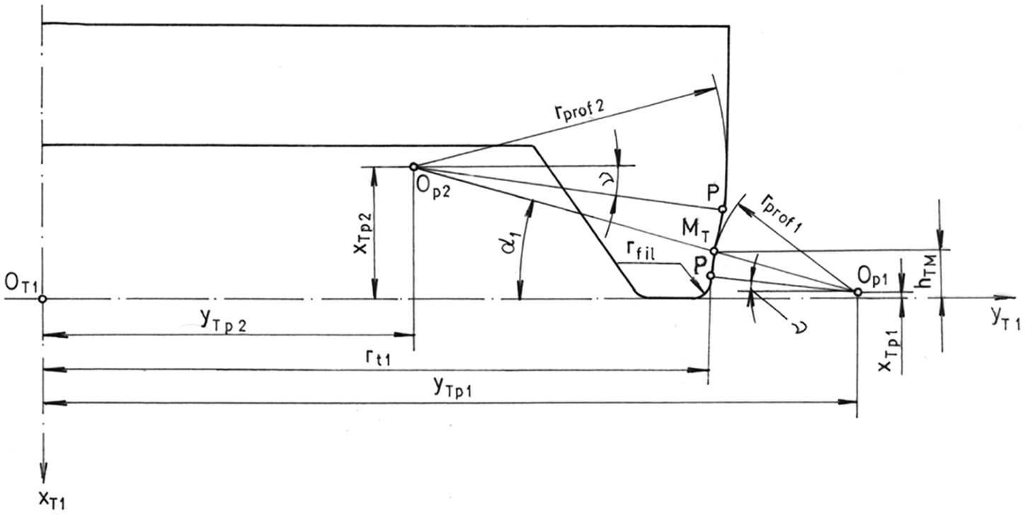
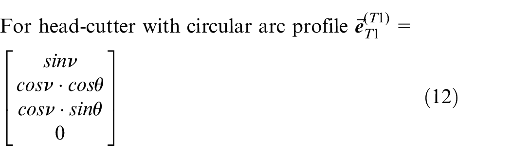
Head-cutter with circular arc profile.
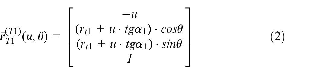
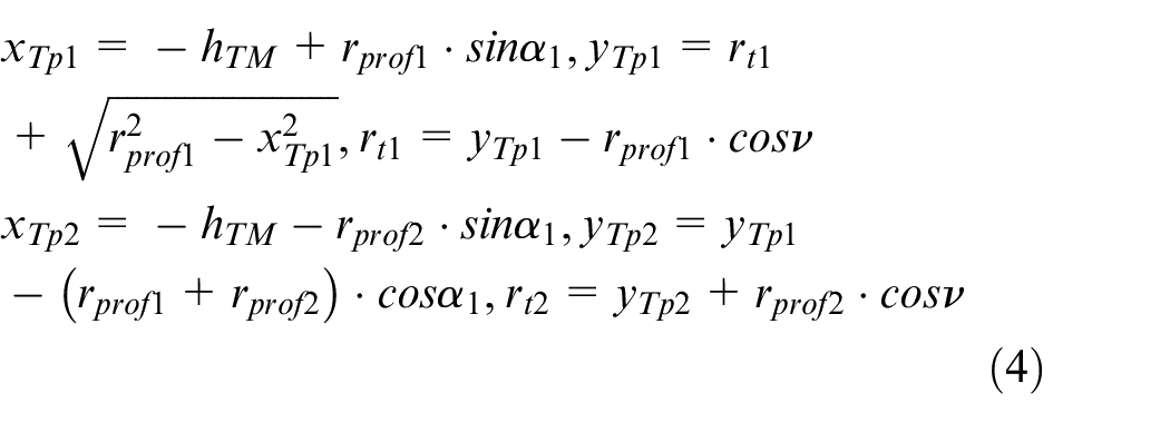
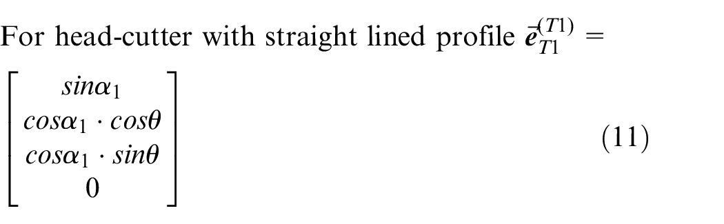
The equation of the head-cutter surface with straight line profile (Figure 1) is:
The equation of the head-cutter with circular arc profile (Figure 2) is:
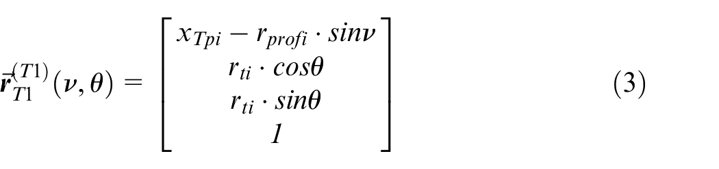
where i = 1, 2 is for the two circular arcs, and
Matrices
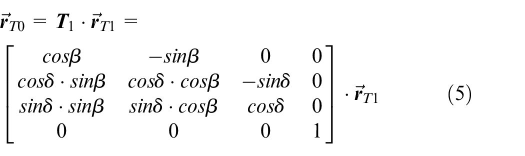
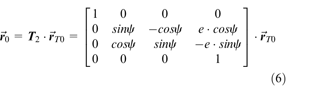
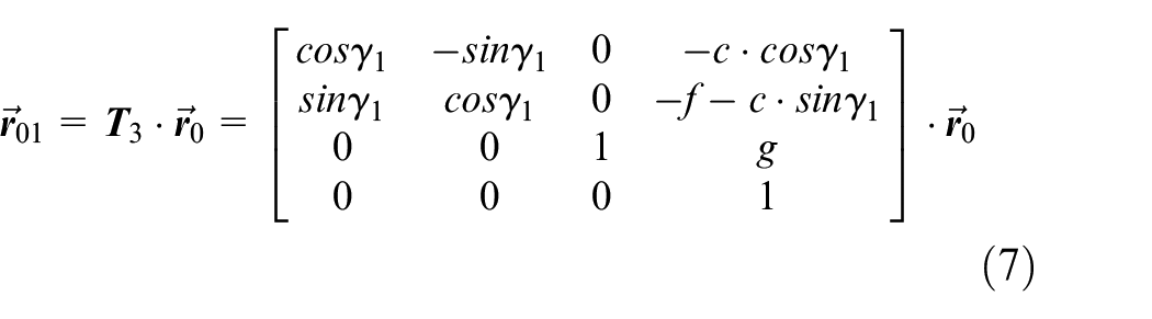
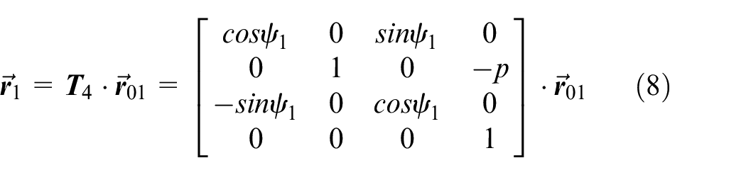
where
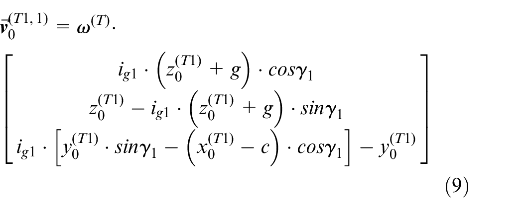
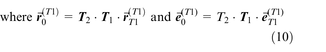
For the velocity vector
The multi-objective optimization model
In the developed multi-objective optimization model the tooth contact pressure, the transmission error, and the energy losses in the gear mesh are minimized by appropriate variation of the machine tool settings and tool geometry. The optimization procedure is based on the loaded tooth contact analysis (LTCA) 40 and on the mixed thermal elastohydrodynamic analysis of lubrication (EHL). 41
The elements of the multi-objective optimization are as follows.
The variation functions for machine tool settings
The machine tool settings are defined in Figure 1. The variation of machine tool settings is conducted by the following polynomial functions of fifth-order:
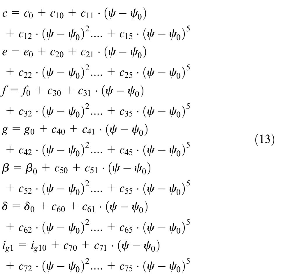
where
Therefore, the maximum tooth contact pressure,
Objective functions and constraints
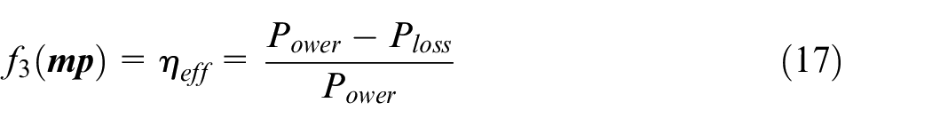
The objective functions expressing the goal of the optimization are as follows:
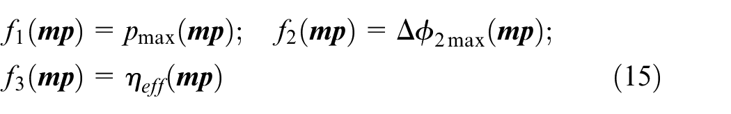
Methods for the determination of the objective functions:
The discrete values of function
Function
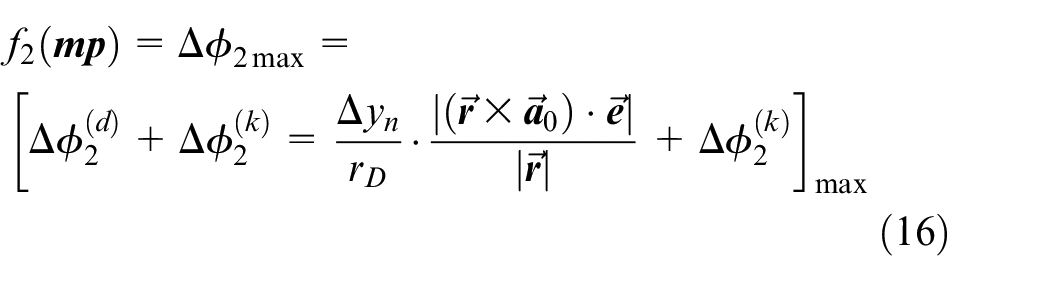
where
Function
where
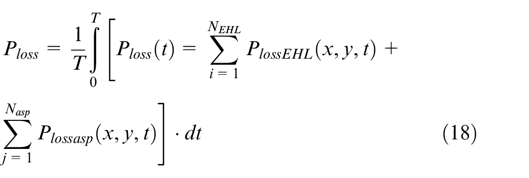
where T is the time of one mesh cycle.
The method for the calculation of power losses
Objective function and constraints
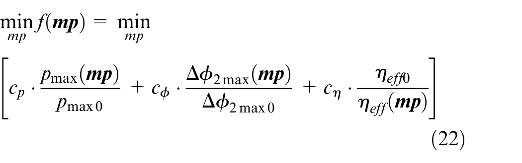
The objective function can be expressed as
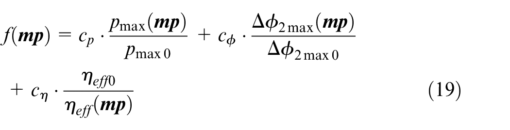
where
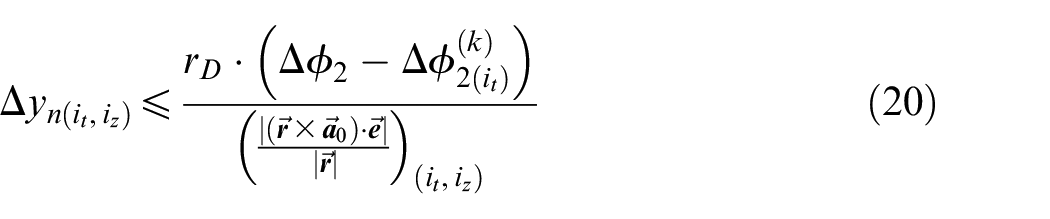
The constraints define the contour of the instantaneous contact area, namely the border of tooth surface points with/without acting load. For the instantaneously loaded tooth contact points, based on LTCA, the following condition is satisfied 40 :
In the instantaneously not loaded tooth surface points C is initialized to zero:

The optimization problem to be solved is as follows:
subject to
Solution of the optimization problem
The objective function,
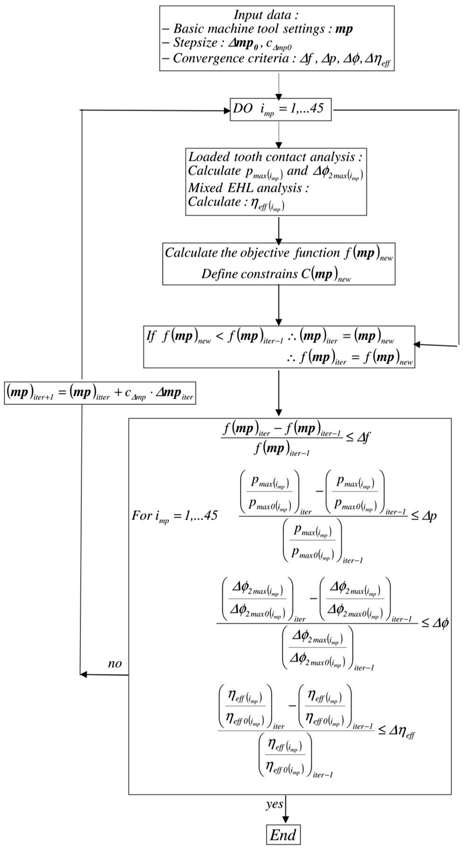
Flowchart of the computer program algorithm.
Manufacture of hypoid gears on numerical controlled machine tool
The numerical controlled machine tool for hypoid gear manufacture with six degree freedom is shown in Figure 4. There are three rotational motions (
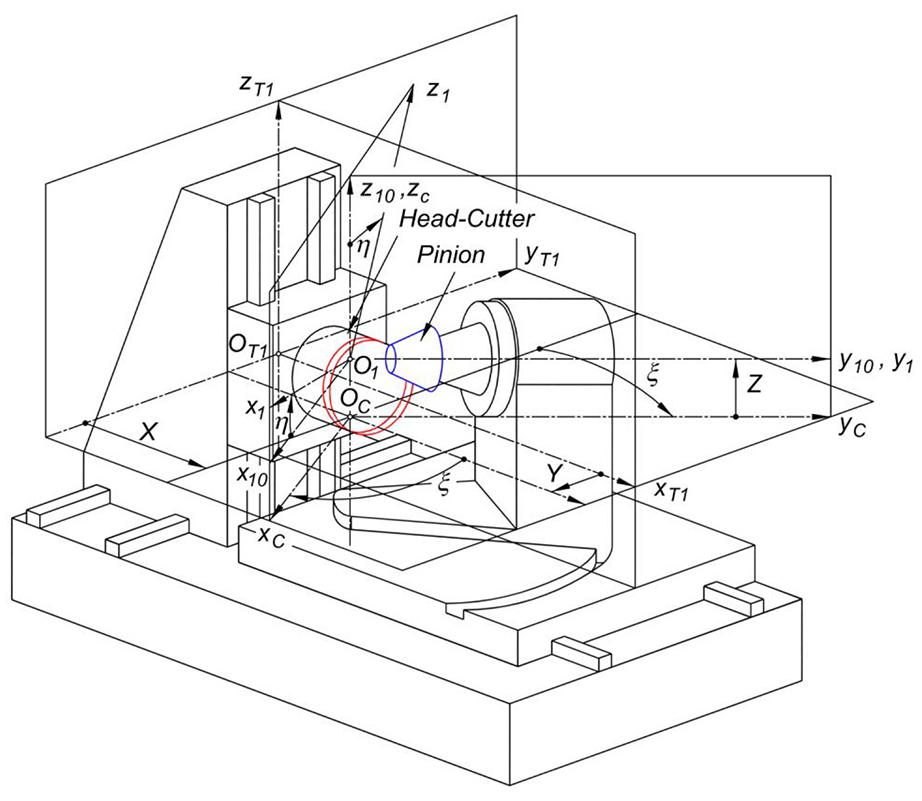
Motions on the machine tool with numerical control for hypoid gear manufacture.
Coordinate systems
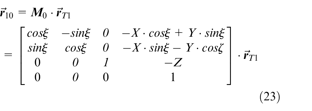
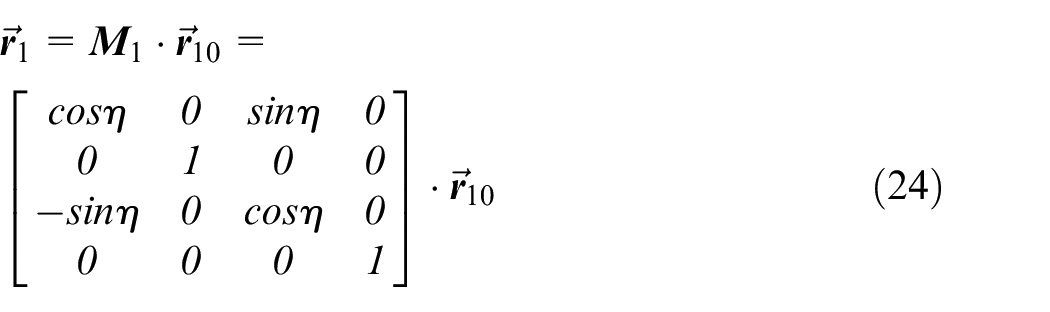
Therefore, it follows:
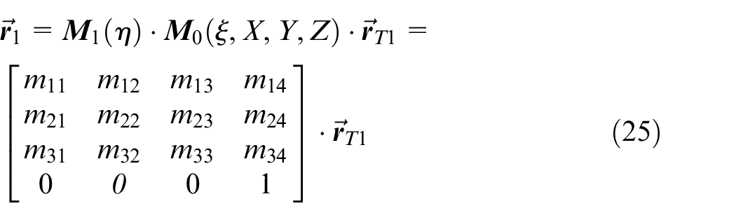
An algorithm is developed for the transformation of motions from the cradle-type machine for hypoid gear manufacture to the computer controlled machine. The algorithm is based on the rule that the relative position of the head-cutter and the pinion must be the same on both machines. This condition can be expressed by the following equations:
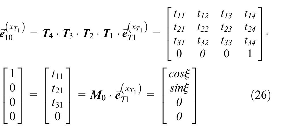
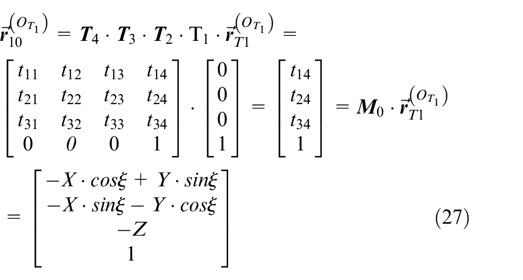
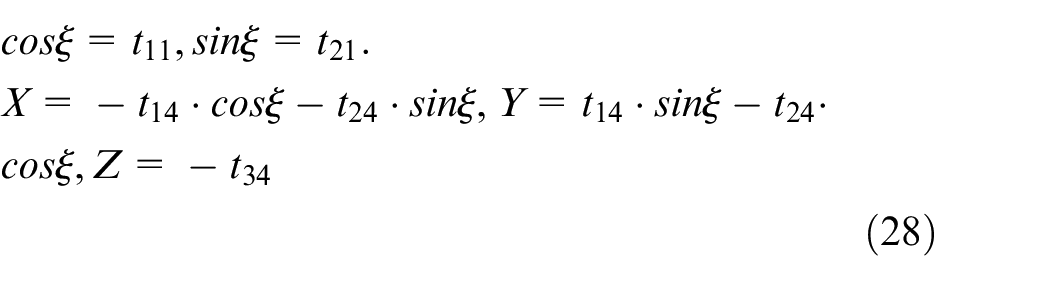
From equations (26) and (27) it follows:
The equality of the rotation angle of the pinion on the two machine tools is expressed by the following equations

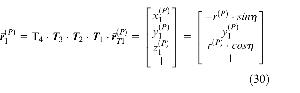
From equation (30) it follows:
The variation of motion parameters on the numerical controlled machine tool for hypoid gear processing can be expressed in function of the cradle angle on the cradle-type machine tool,
Computed results
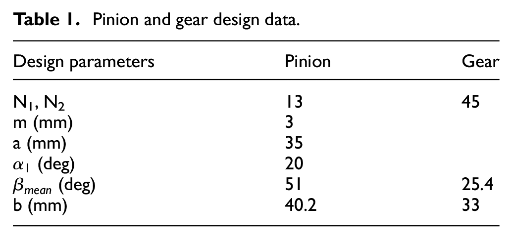
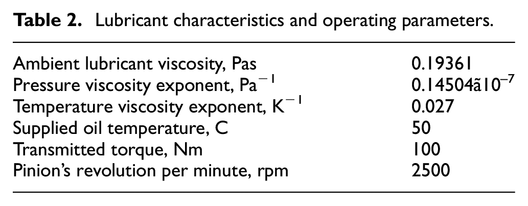
Based on the presented theoretical background a computer program was developed. The calculations were performed for the hypoid gear pair with design data presented in Table 1. The data for the thermal elastohydrodynamic calculation are presented in Table 2.
Pinion and gear design data.
Lubricant characteristics and operating parameters.
The calculations were made for 31 instantaneous mating positions of the gear pair. The calculated pressure distributions along the potential contact lines of tooth surfaces for these 31 instantaneous mating positions and the calculated values of operating characteristics of the gear pair (maximum tooth contact pressure,
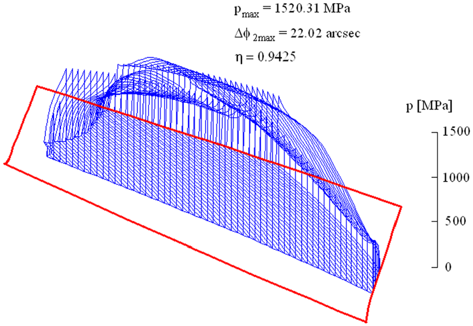
Tooth contact pressure distribution for the hypoid gear pair manufactured by usual applied machine tool settings.
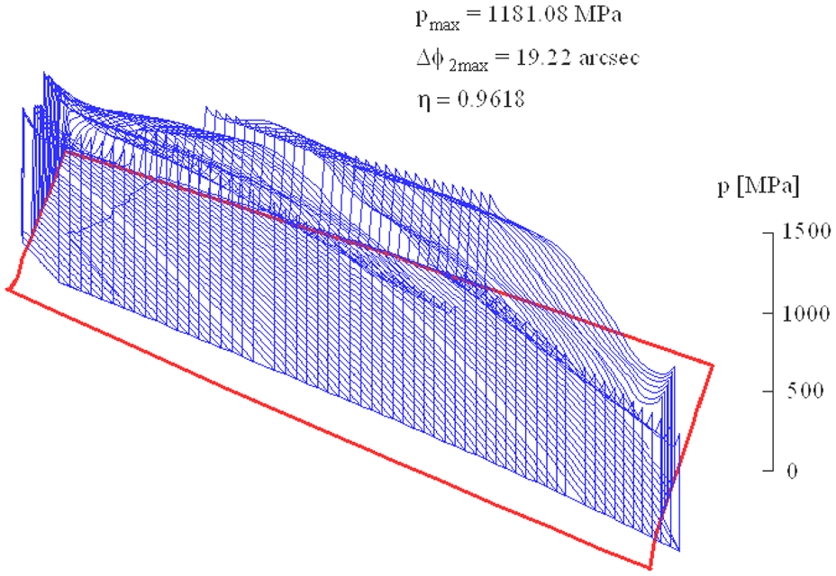
Tooth contact pressure distribution when the pinion teeth are manufactured by the head-cutter of optimized geometry and by optimal variation in machine tool settings.
It can be considered that by the introduction of the optimized manufacture procedure the maximum tooth contact pressure is reduced from 1520 MPa to 1181 MPa, the maximum angular displacement error of the driven gear from 22.02 arcsec to 19.22 arcsec, and the efficiency of the gear pair is increased from 0.9425 to 0.9618.
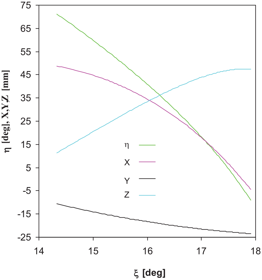
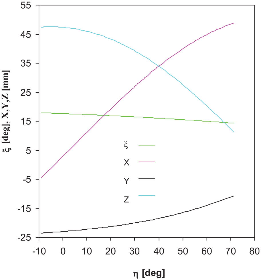
The graphs in Figures 7 to 10 represent the execution of motions on the numerical controlled machine for the manufacture of hypoid gears conducted by polynomial equations (13) with optimized coefficients. In these figures, X is the horizontal setting of the cutting spindle, Y is the sliding base setting, Z is the vertical setting of cutting spindle,
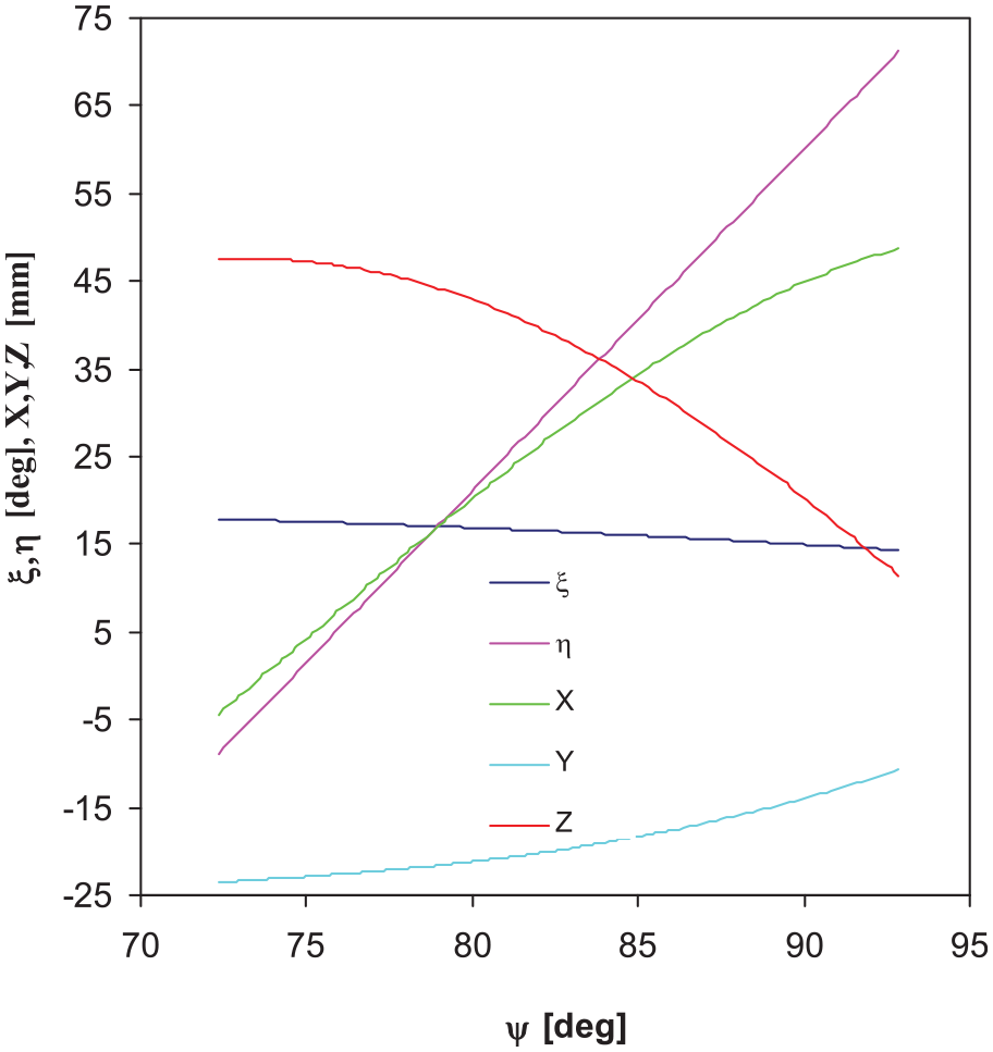
Motion graphs for the numerical controlled machine in function of the cradle angle of the cradle-type generator.
Motion graphs for the numerical controlled machine in function of the swinging base rotation angle of the CNC machine.
Motion graphs for the numerical controlled machine in function of the pinion’s rotation angle.
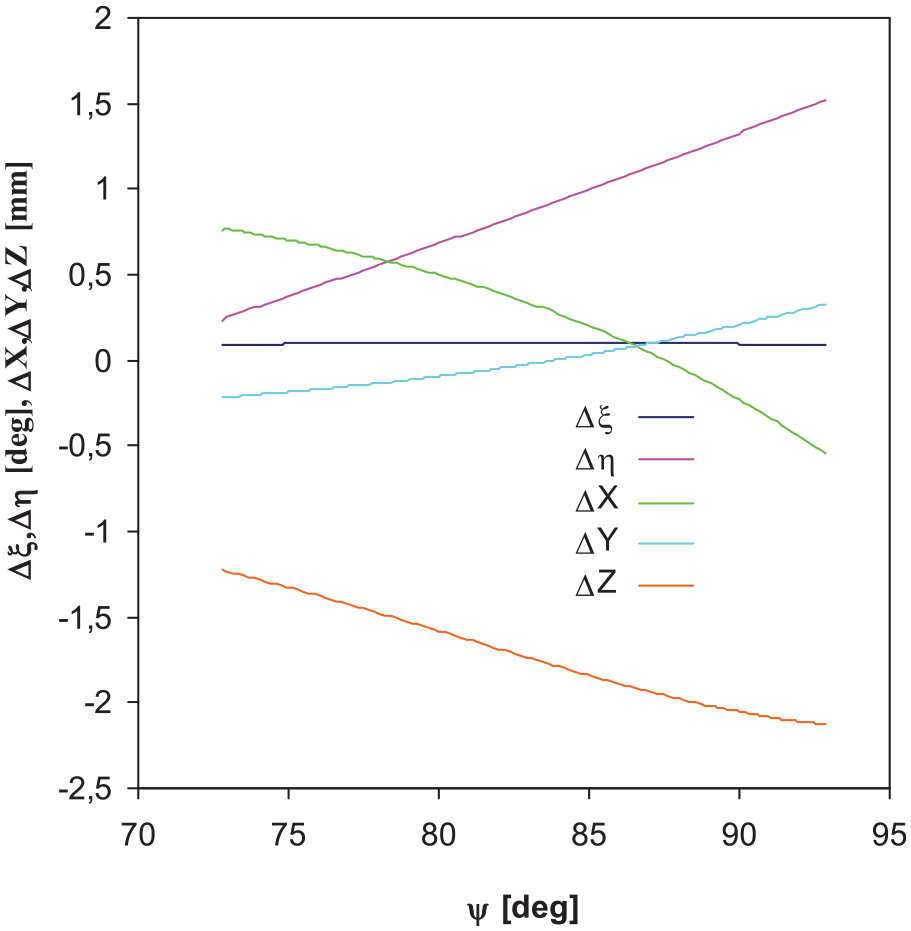
Differences in motions on the numerical controlled machine for the cases when the hypoid pinion is manufactured with optimized and not optimized manufacture processes.
Conclusion
A new multi-optimization method for processing hypoid gears on numerical controlled machine is presented. The goal is to improve the operating characteristics of the hypoid gear pair. The variation of motions on the numerical controlled machine is conducted by polynomial functions of fifth-order. By applying the developed computer program, the operating characteristics of the hypoid gear pair are considerable improved, as it follows:
The maximum tooth contact pressure is reduced by 22.3%, the angular displacement error of the driven gear by 12.7%, and the efficiency of the gear pair is increased from 0.9425 to 0.9618. Therefore, by the optimization of the manufacture of hypoid gears on computer controlled machines the gear life can be considerably increased, the dynamic load and the gear noise can be considerably reduced. It should be mentioned that the reduction of power losses in the gear pair is nowadays of big importance.
The novelty of the new method is that during the machining process of teeth surfaces, the variation of machine tool settings on the cradle-type hypoid generator is conducted by optimized polynomial functions of fifth-order, and this variation of machine tool settings is transferred to the numerical controlled machine tool for hypoid gear manufacture (hypoid generator) by a new algorithm. Therefore, by applying this new method in practice, advanced manufacture of hypoid gears on the CNC hypoid generator is made possible, resulting improved operating characteristics of the hypoid gear pair.
Footnotes
Appendix
Declaration of conflicting interests
The author(s) declared no potential conflicts of interest with respect to the research, authorship, and/or publication of this article.
Funding
The author(s) disclosed receipt of the following financial support for the research, authorship, and/or publication of this article: The research reported in this paper was supported by the Higher Education Excellence Program of the Ministry of Human Capacities in the frame of Artificial intelligence research area of Budapest University of Technology and Economics (BME FIKP-MI), and by the National Research, Development and Innovation Fund (TUDFO/51757/2019-ITM, Thematic Excellence Program).