
Abstract
In the aerospace field, difficult-to-machine materials are used widely to improve engine performance. As a nickel-based material that performs well in all aspects, Inconel 625 is used for the blisks of aircraft engines, and electrochemical trepanning (ECTr) is used widely to fabricate such blisks because of its unique advantages regarding ruled surface parts. In this study, to investigate the performance of Inconel 625 in ECTr, measurements were made of the electrochemical characteristics firstly, specifically the anodic polarization curve and the actual volumetric electrochemical equivalent curve. Then, via dynamic electric-field simulations, the processes for forming Inconel 625 blades using ECTr were examined under direct voltage (DV) and pulsed voltage. The contours and current density distributions of formed blades at different times were obtained under different duty cycles. With decreasing duty cycle, the forming accuracy improved gradually and the stray current was reduced. To verify the simulation results, ECTr experiments with Inconel 625 were performed under different voltage conditions. With DV and 90% and 80% duty cycle, the taper angles of the machined blades were 7.784°, 6.278°, and 5.191°, respectively, and the surface roughness (Ra) values were 0.95, 0.81, and 0.72 μm, respectively. With DV, there were obvious flow marks and gullies on the microscopic surface. With decreasing duty cycle, stray corrosion was reduced effectively and the state of the flow field was improved. Overall, the simulation results were verified effectively.
Introduction
Because of their excellent mechanical properties and corrosion resistance at high temperature, nickel-based alloys are used extensively in key components in the aerospace field. 1 As a typical nickel–chromium alloy, Inconel 625 superalloy has high tensile, creep, and rupture strengths and outstanding fatigue and thermal-fatigue strengths. The service temperatures of Inconel 625 range from cryogenic to 982°C, 2 and Inconel 625 has excellent weldability and brazeability. 3 The properties of Inconel 625 make it an excellent choice for the blades of aeroengines to improve performance. 4 Under the stiffening effect of molybdenum and niobium on its nickel–chromium matrix, Inconel 625 is extremely strong, thereby making it difficult to process with conventional milling. 5 Electrochemical machining (ECM) is a non-contact machining technique based on electrochemical anodic dissolution.6–8 Because of its advantages of (i) being independent of the physical properties of the target material and (ii) producing no recast layers or residual stress, among other advantages, ECM is very suitable for machining difficult-to-cut materials such as Inconel 625. 9
Electrochemical trepanning (ECTr) is an effective ECM method. 10 For the blades of aero engines, there are many ruled surface parts, which refer to surface parts produced by a straight line moving according to a certain trajectory. The equal cross-sectional blades are ruled surface parts. Due to the unique processing characteristics, ECTr has unique advantages for manufacturing ruled surface parts. 11 In ECTr, the parts are formed through the relative movement between a hollow shaped cathode sheet and the workpiece. The focus herein is on improving the machining quality of blades formed from Inconel 625 using ECTr.
There has been much previous research on enhancing the machining quality of ECM. An ethylene glycol–NaCl electrolyte solution was added to promote the machining quality of NiTi shape-memory alloy in electrochemical micromachining. 12 How differences between the inward and outward flow modes in the suction tool affected the characteristics of ECM was investigated. 13 To enhance the machining accuracy of radial ultrasonic rolling micromachining, a set of suitable gap pressure parameters was optimized. 14 By using a pulsating electrolyte, the surface quality of the workpiece was improved. 15 In straight bevel gear finishing, the differences of performance between pulsed-electrochemical honing and finishing were compared. 16 There has also been much previous research on enhancing the machining quality of ECTr. A new dynamic lateral flow mode was proposed that resulted in higher machining quality. 17 The flow field became more stable by adding a back pressure at the outlet, and the surface quality was greatly improved. 18 In ECTr, the machined regions of the blade were suffered from secondary corrosion under the influence of stray currents, thereby affecting the machining quality of the blade. 19 To decrease stray corrosion during ECTr, the methods of blowing gas onto the machined region 20 and adding ceramic insulating particles in the cathode cavity 21 were developed. However, although the machining quality of ECTr has been improved in many aspects, there is a lack of literature on blades of Inconel 625 formed using ECTr. Therefore, it is very necessary to improve the machining quality of Inconel 625 material by ECTr. So the research of this article was carried out.
In the present study, to investigate such blades, the electrochemical characteristics of the material were measured first, specifically the anodic polarization (AP) curve and the actual volumetric electrochemical equivalent (AVEE) curve. To examine the process of forming blades in ECTr under direct voltage (DV) and pulsed voltage (PV), dynamic electric-field simulations were carried out under different duty cycles and a series of ECTr experiments was performed; the experimental results verify the simulation results. Also, the mechanism of ECTr with PV was analyzed. The machining quality of Inconel 625 can be enhanced effectively by using PV in ECTr, and the present results can be used to guide other ECM processes on Inconel 625.
Electrochemical characteristicsof Inconel 625
To study the performance of Inconel 625 in ECM, measurements were made first of the AP and AVEE curves. The AP curve reflects the relationship between the anode electrode potential and the corresponding current density. By using an electrochemical workstation (Zennium E; Zahner, Germany), a calomel electrode and a platinum electrode were used as the reference electrode and the counter electrode, respectively. The dimensions of the measurement specimen were 10 mm × 10 mm × 10 mm. Linear scanning was used with a scanning rate of 0.1 mV/s and a scanning interval from −2 to 3 V.
The anode polarization curve of Inconel 625 in 20-wt% NaNO3 solution at 30°C is shown in Figure 1, from which the following conclusions are drawn. (1) Inconel 625 has an obvious passive region in which the current density is substantially stable. This can be attributed to the presence of a passivation film on the surface of the material, under the protection of which the corrosion rate of the metal is greatly reduced and the material is basically non-corrosive. (2) When the voltage exceeds 0.537 V, the passivation film breaks and the dissolution of Inconel 625 moves into the transpassive region. The material corrosion is now in a transpassivation state in which the current density increases sharply with increasing voltage.
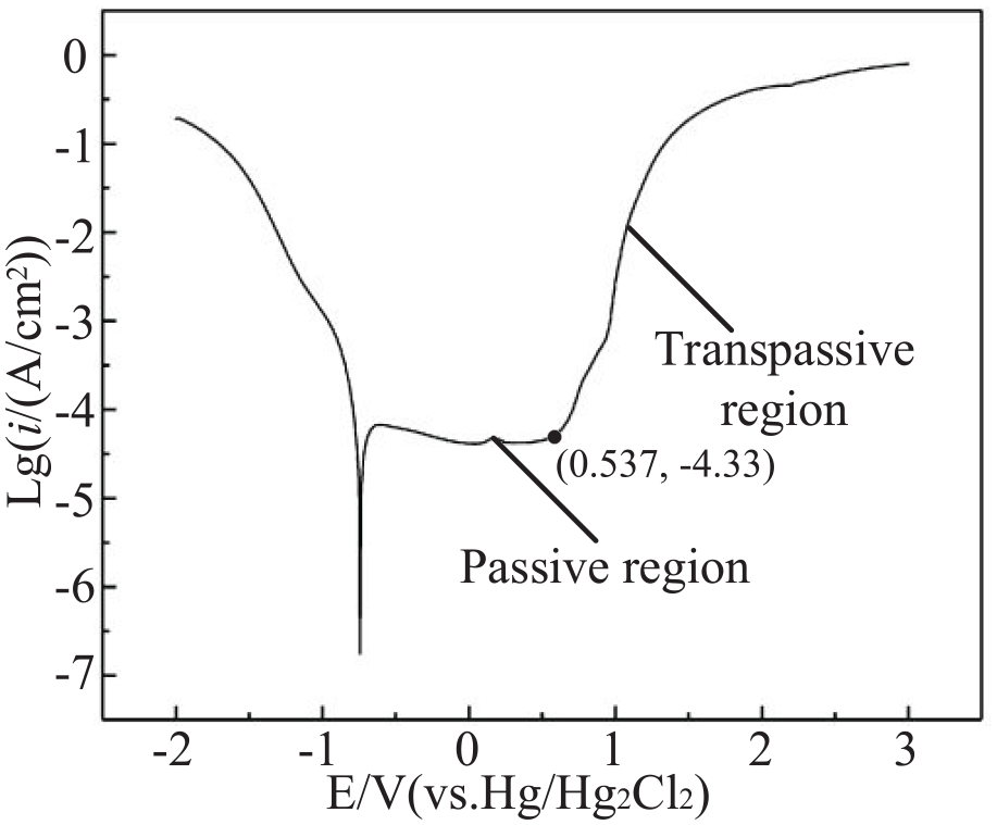
Anodic polarization curve of Inconel 625 in 20-wt% NaNO3 solution.
In ECM, the current efficiency curve (η–i curve) characterizes the relationship between the effective utilization efficiency of electricity and the current density during the machining process. According to Faraday’s law, the current efficiency of the material can be obtained as 22
Where η is the current efficiency, ω is the volumetric electrochemical equivalent of the material, V is the dissolved volume of anode material, Q is the amount of electricity passing between the electrodes, M is the quality of the material removed within the machining time t, ρ is the density of the material, i is the current density, and s is the machining surface area. Generally, the product of η and ω (ηω), known as the AVEE, is considered as providing process data.
For a given machining time (t) and machining surface area (s), the corresponding relationship between the AVEE and the current density (ηω–i) can be obtained by calculating the material removal quality. To measure the ηω–i curve of Inconel 625, a series of experiments was performed with the experimental parameters given in Table 1, from which the ηω–i curve of Inconel 625 was fitted (Figure 2).
Parameter values used to measure current efficiency curve of Inconel 625.
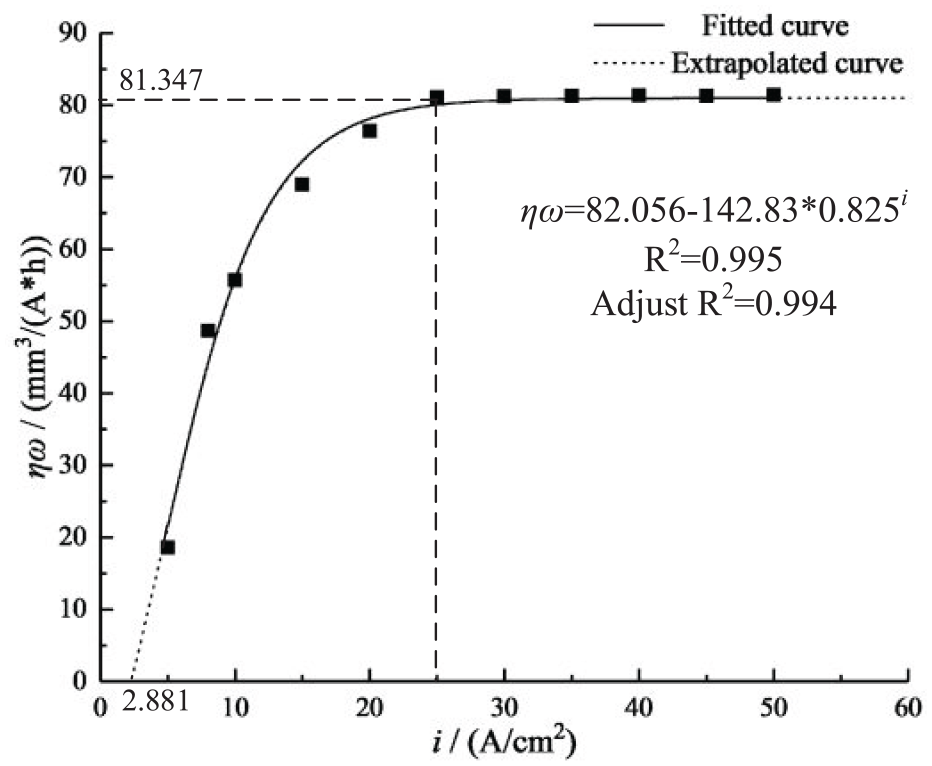
Current efficiency curve of Inconel 625 in 20-wt% NaNO3 solution.
From the ηω–i curve of Inconel 625, the following information was obtained. (1) When the current density was less than 25 A/cm2, the current efficiency of the material increased sharply with increasing current density. At that time, the value of ηω was 81.347 mm3/(Ah). (2) As the current density continued to increase, the current efficiency basically did not change. The stable value of ηω was 82.056 mm3/(Ah). (3) From the extrapolated fitted curve, when the current density was less than 2.881 A/cm2, the material was no longer dissolved. That was because the passivation film on the surface of the material was not broken. This section of the ηω–i curve corresponded to the passivation region in the AP curve.
Methods of simulation and experiment
Principle of blade in ECTr
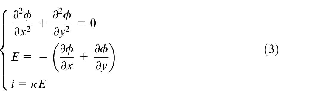
To study the formation of a blade from Inconel 625 using ECTr, two voltage modes were designed, that is, DV and PV. Under DV, the machining voltage was constant and material was removed continuously. Under PV, the voltage varied with a specific period. A blade in ECTr is shown schematically in Figure 3. In ECTr, a hollow metal sheet is used as the cathode, and as this moves toward the workpiece along the feeding trajectory, a blade with a contour slightly smaller than that of the cathode machining edge is formed (Figure 3(a)). As shown in Figure 3(b), the power supply provided a constant voltage, and a rectangular wave with controllable frequency and duty cycle was modulated via the pulse generator and applied to the electrodes. Electrolyte flowed at high speed in the machining gap, and material was removed intermittently during the whole process. Only when there was a voltage did the electrochemical reaction occur; in the absence of a voltage, the electrolyte removed the machining products quickly.
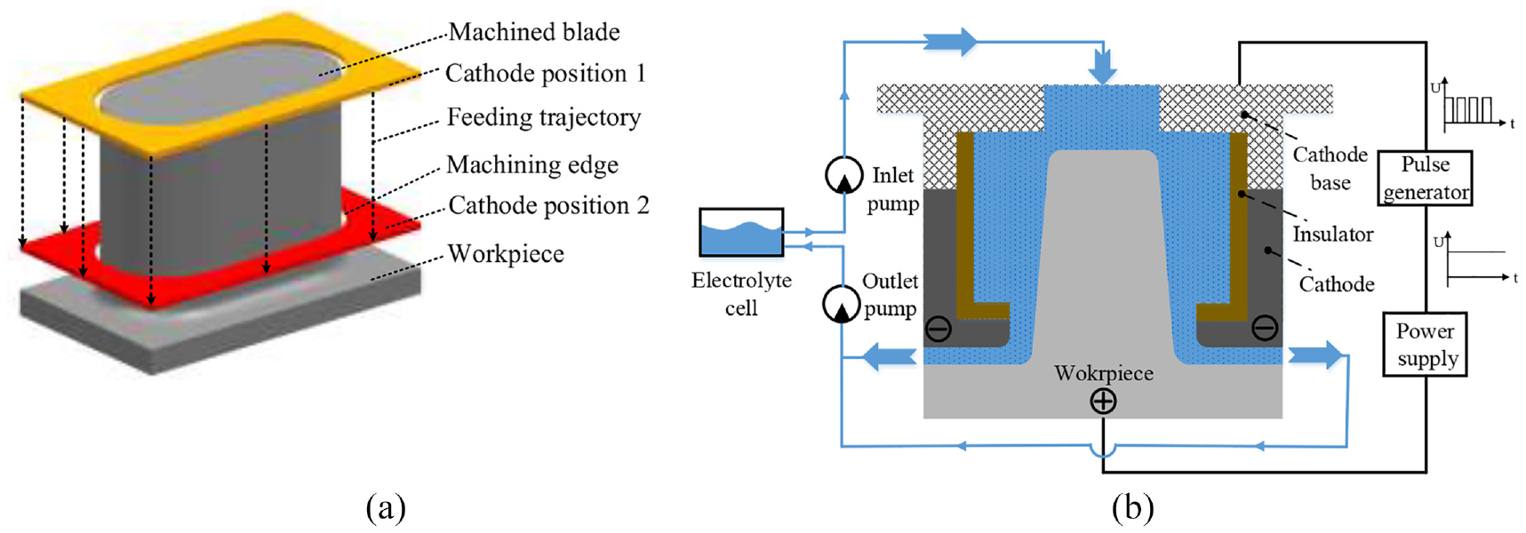
Schematics of blade in electrochemical trepanning (ECTr): (a) formation of blade and (b) machining process.
Simulation details of ECTr
To examine the process of forming a blade from Inconel 625 using ECTr, dynamic electric-field simulations were performed under different voltage modes. To simplify the simulation model, the gas bubbles generated on the electrodes and the Joule heat produced by the current heating effect were neglected because of the relatively short electrolyte flow path. First, a mathematical model was established.
ECTr is based on the principle of anodic dissolution. According to Faraday’s laws, the dissolution rate va of the anodic material is related to the AVEE (ηω) and the current density (i) as 23

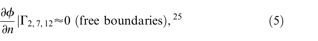
The potential distribution of the entire electric field in ECTr conforms to the Laplace equation. The current density during machining is related to the electric field strength and the conductivity of the electrolyte. In two dimensions, the distribution of electric field can be expressed as 24
Where ϕ is the electrical potential in the inter-electrode gap, E is the electric field strength, and κ is the conductivity of the electrolyte.
The two-dimensional geometrical model of ECTr is shown in Figure 4. In the model, the initial machining gap (Δ) is 0.5 mm, the thickness of the cathode sheet (a) is 1 mm, the widths of the cathode base (b) and the insulator (c) are 0.7 and 2.5 mm, respectively, the thickness of the insulator (d) is 0.2 mm, the height (e) and width (f) of the cathode cavity are 9 and 8.2 mm, respectively, the distance between the cathode edges (g) is 3.6 mm, the width of the workpiece (h) is 10 mm, and the radius of the fillet (r) is 0.8 mm. Based on the actual ECTr process, the boundary conditions are


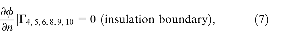
Where n is the unit normal vector of the surface.
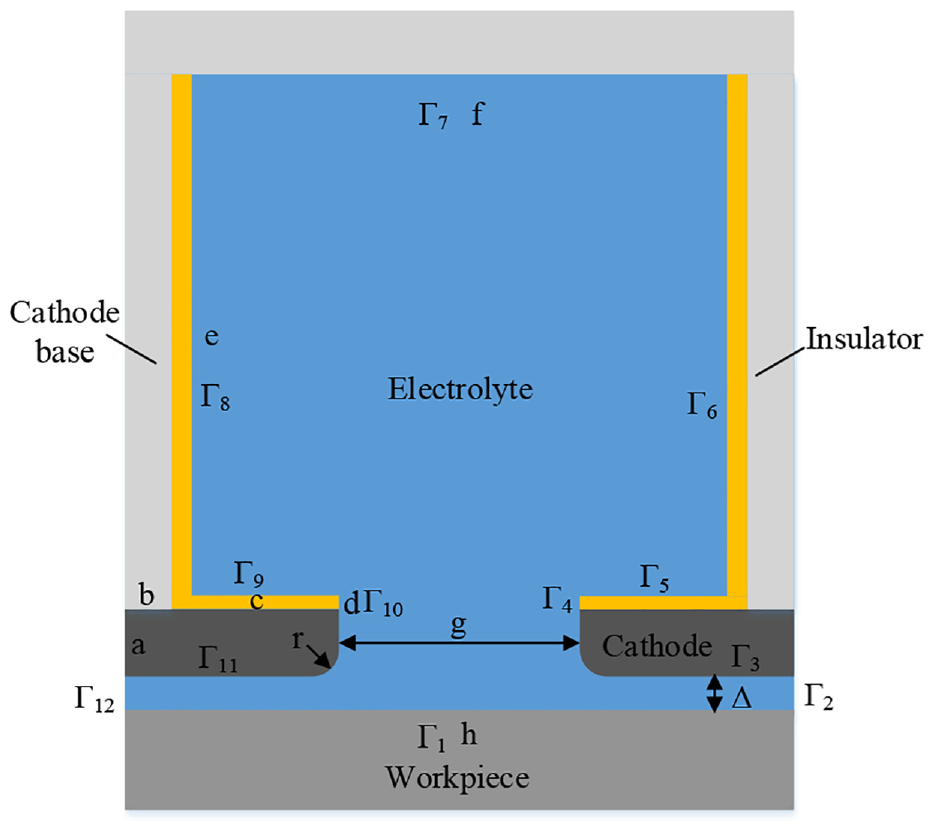
Geometrical model of ECTr.
When a voltage is applied to the geometrical model described above, according to Ohm’s law, the potential difference generates a certain current between the workpiece and the cathode in the electrolyte environment. Then, from equation (2), the anode material is dissolved according to the material characteristics and the current density. With the hollow cathode moving toward the workpiece at a constant speed, the anode material is dissolved continuously, and a blade with a shape smaller than the machining edges is formed gradually.
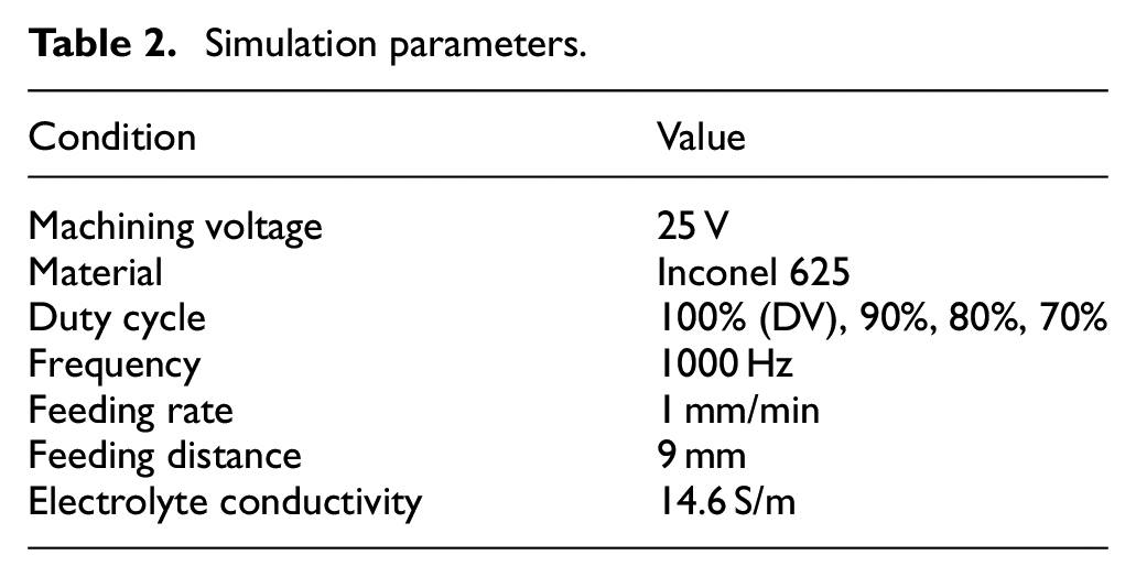
Using the above model, dynamic electric-field simulations were performed using the COMSOL Multiphysics software with the simulation parameters given in Table 2.
Simulation parameters.
Experimental details of ECTr
An experimental ECTr system was built, which included a power supply system, an electrolyte circulation system, and a machine-tool motion system (Figure 5). In the power supply system, the DV mode was achieved through a DC power supply and could be switched to the PV mode by means of a pulse generator and a controller; the frequency and duty cycle of the pulse waveform could also be adjusted. In the machine-tool motion system, the workpiece was placed on the worktable and the cathode was fixed on the spindle of the machine tool; during machining, relative movement between the workpiece and the cathode was realized through the movement in the Y direction, and the feed in the depth direction of the workpiece was completed. In the electrolyte circulation system, pure electrolyte entered the machining area under a constant electrolyte inlet pressure, and the temperature of the electrolyte was adjusted by using a heat exchanger after temperature feedback throughout the machining process.
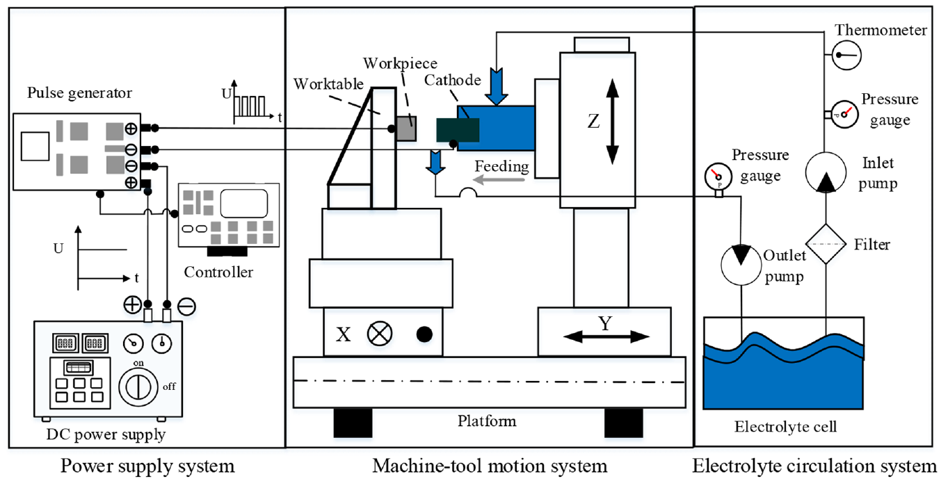
Schematic of experimental setup.
In the experiments, the inlet pressure was 0.8 MPa, the electrolyte temperature was 30°C, and the shape of the cathode was consistent with that in the simulation model. The workpiece material used in the experiments was Inconel 625, and the other conditions were the same as those in the simulations.
Results and analysis
Through the dynamic electric-field simulations and the ECTr experiments, results were obtained under different voltage modes, and the reasons for the changes in machining accuracy and surface quality of the machined blades under different voltage modes were analyzed.
Simulation results and analysis
Through the simulations, the contour shapes and current density distributions of blades machined under DV and PV were examined at different times.
Contours of machined blades
Under 70% duty cycle, the dynamic electric-field simulation could not continue beyond 88.3 s, at which time an error occurred, as shown in Figure 6. The cathode and anode boundaries intersected, that is, a short circuit may occur during the actual processing.
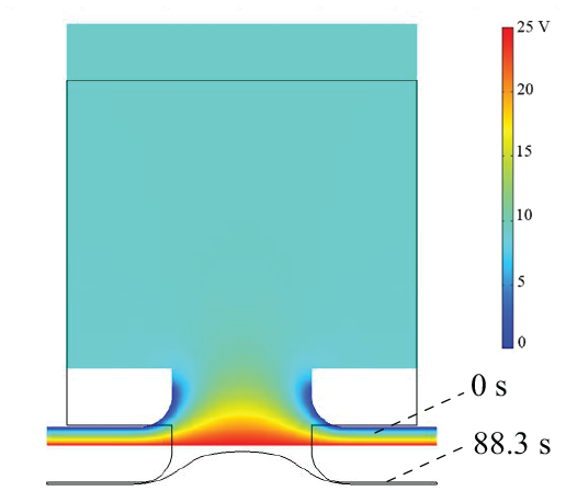
Simulation error under 70% duty cycle.
When the duty cycle was 80%, 90%, or 100% (DV), the simulation ran normally until the end of processing. By extracting the anode boundary at different times, the blade formation process was mapped under different voltage parameters (Figure 7), and the contours at different times were compared under different conditions (Figure 8).
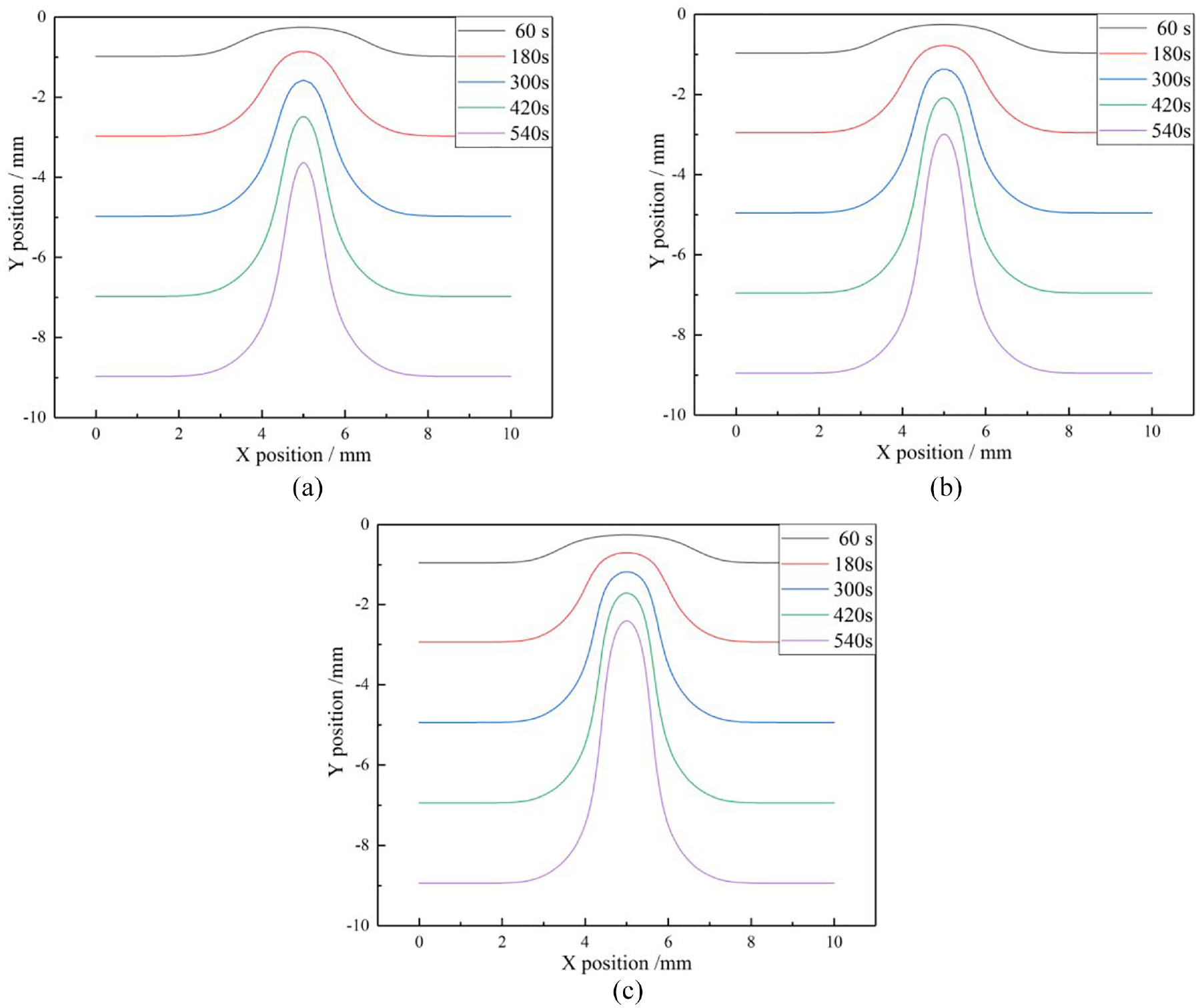
Blade formation process under different voltage parameters: (a) constant voltage, (b) 90% duty cycle, and (c) 80% duty cycle.
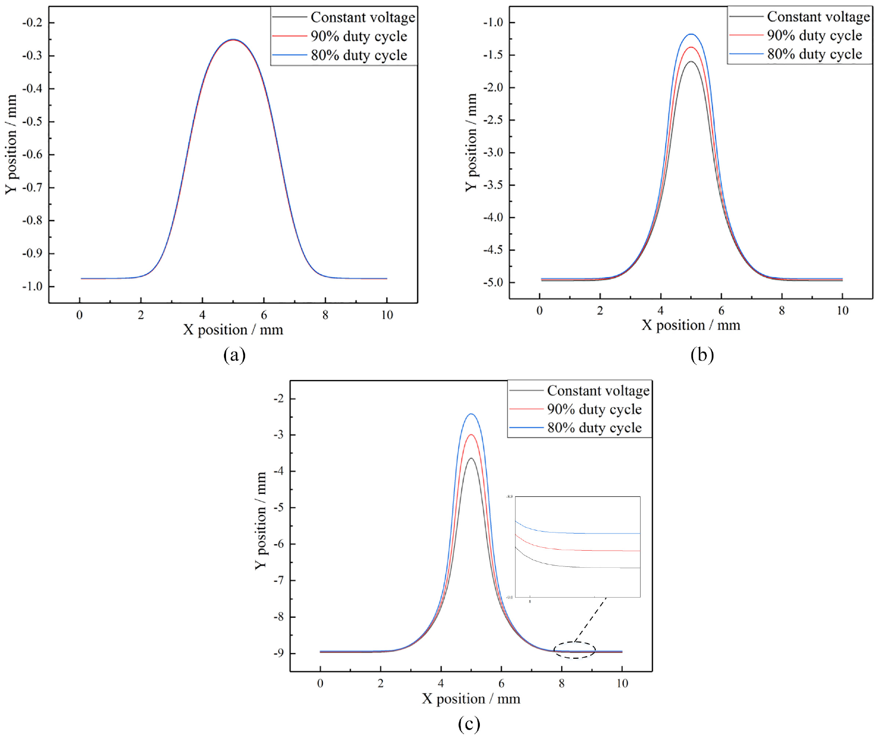
Blade contours at given times under different voltage conditions: (a) 60 s, (b) 300 s, and (c) 540 s.
To evaluate the blade machining accuracy, the taper angle (γ) is used here (Figure 9) and is calculated as 26

Where dB is the distance between the blade top and bottom, and L is the length of the detection line.
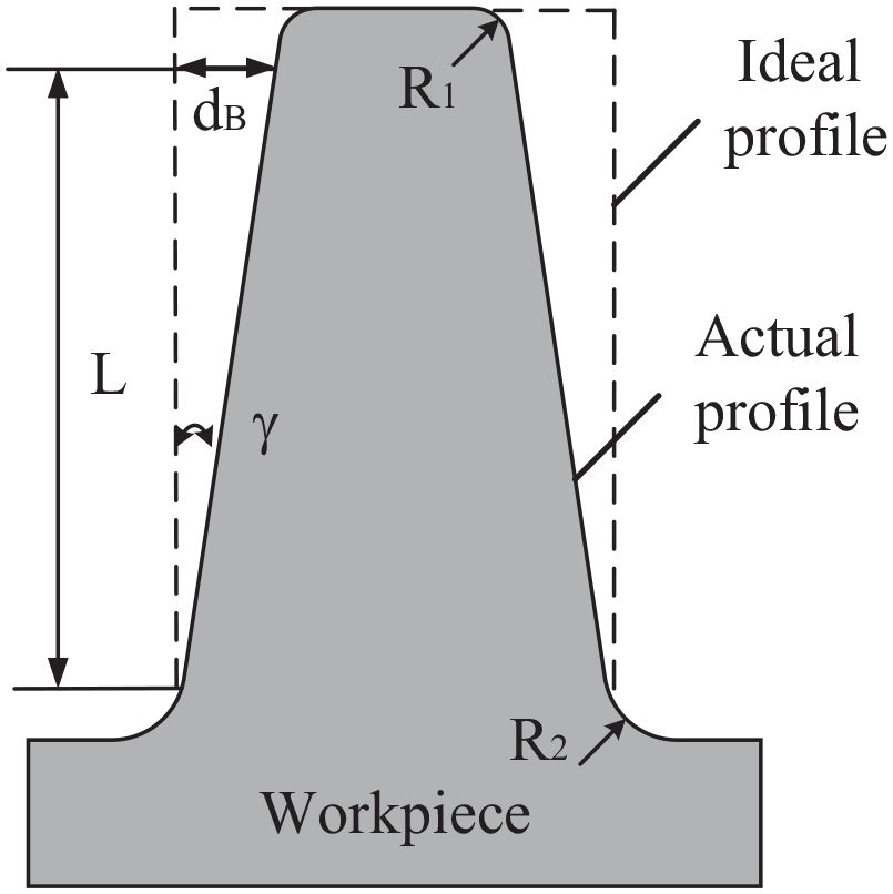
Definition of blade taper angle.
The following information is obtained from the simulations results regarding the contours. (1) To ensure normal processing, the duty cycle should exceed 70%. Also, as the feed depth increased during blade formation, the blade presented a certain taper because of stray corrosion in the machined blade area. (2) With decreasing duty cycle, the blade taper decreased and the forming accuracy improved. The front-face gap between the cathode and the anode was basically the same under different conditions but decreased slightly with decreasing duty cycle. (3) At a given time, the degree of stray corrosion suffered by the blade was different under different voltage parameters. After processing for 60 s, as shown in Figure 8(a), the predicted contours were basically coincident. This was because the feed speed of the cathode was 1 mm/min and the thickness of the cathode was 1 mm. At this time, the generated blade had not entered the cathode cavity and was unaffected by stray corrosion. (4) After processing for 300 s, the top region of the machined blade was completely in the cathode cavity. The machined blades presented corresponding tapers under the influence of stray corrosion, and the smaller the duty cycle, the smaller the taper. As time passed, the different degrees of stray corrosion caused different blade tapers. At the end of machining, the accuracy of the formed blade decreased with increasing duty cycle.
Current density distribution
The simulations also produced the current density distribution at different times. Taking an 80% duty cycle as an example, the distribution at different times is shown in Figure 10. To examine the difference under different voltage parameters, the current density distribution on the anode boundary at a given time is plotted in Figure 11, where the abscissa is the X coordinate of the processed blade and the ordinate is the current density at this position.
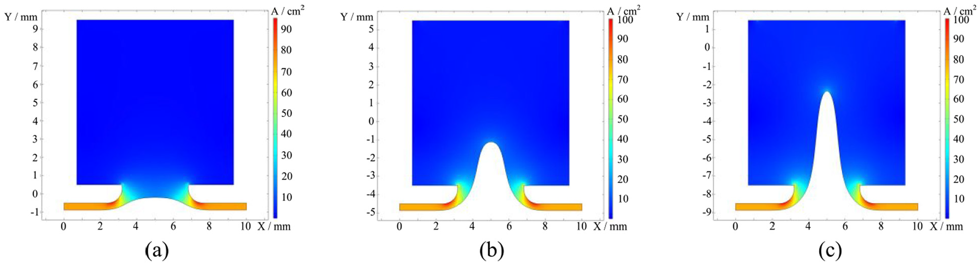
Current density distribution at given times under 80% duty cycle: (a) 60 s, (b) 300 s, and (c) 540 s.
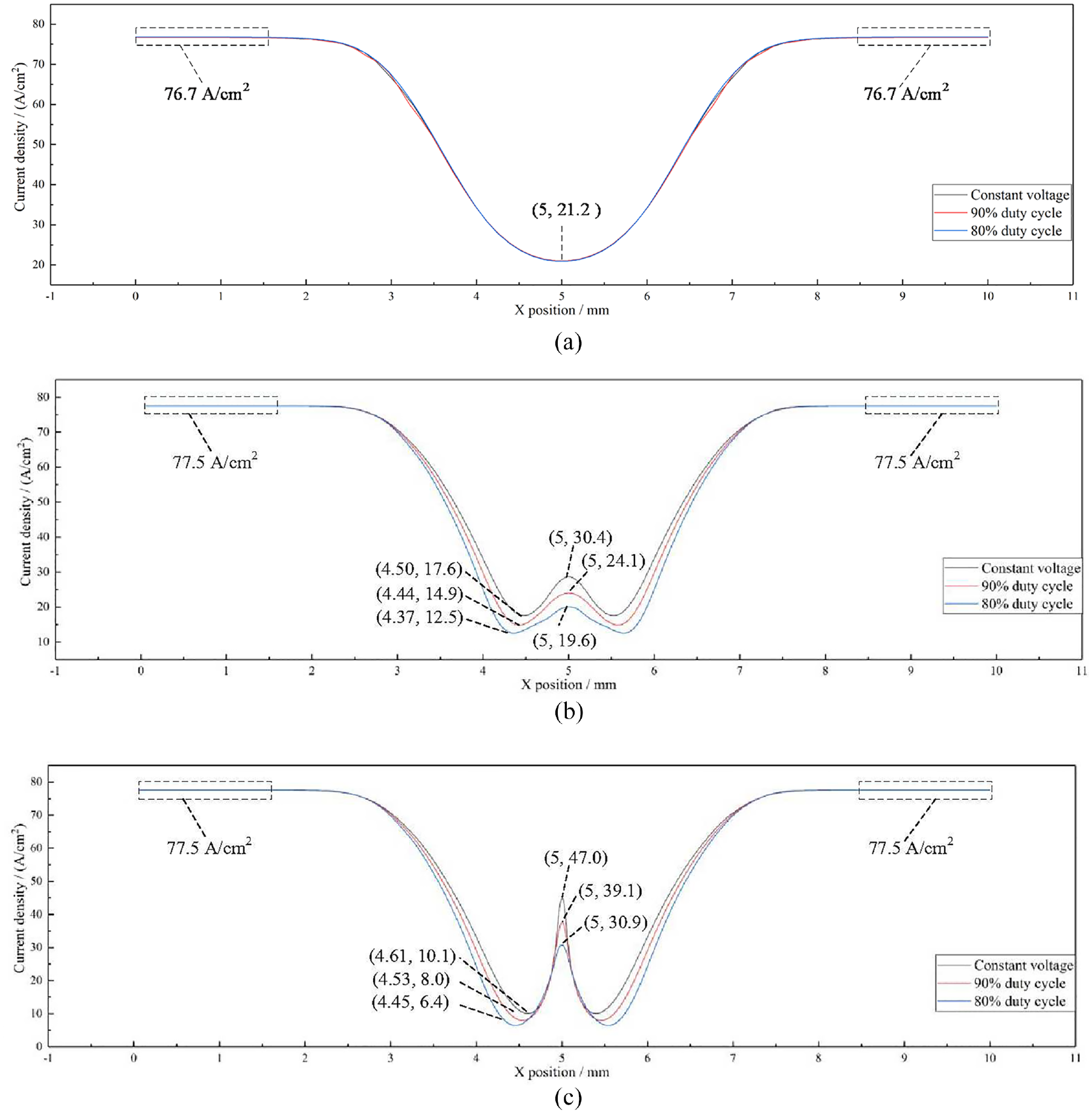
Current density distribution on anode boundary at given times: (a) 60 s, (b) 300 s, and (c) 540 s.
According to Figure 10, the current density distribution was symmetrical about the central axis. The current density of the machined area changed continuously as the processing progressed. The current density at the top of the blade changed significantly because of the tip effect, and the largest current density appeared at the chamfer of the cathode.
The following results are obtained from Figure 11. (1) Under different voltage conditions, the current density at the front face was basically the same. At 60 s, the current density was 76.7 A/cm2, slightly less than the 77.5 A/cm2 at 300 and 540 s. That was because at 60 s, the processing had not fully entered the relative equilibrium state. (2) With decreasing duty cycle, the current density of the machined area of the blade decreased gradually. At 300 and 540 s, the stray current in the tip region under DV was significantly greater than that under PV. (3) The greater the duty cycle, the greater the minimum current density on the anode profile, and the closer the position of minimum current density to the tip area.
Combining the material characteristics of Inconel 625, the machined profiles, and the distributions of current density, the following conclusions are drawn. (1) According to the ηω–i curve (Figure 2), ηω increased sharply with increasing current density when the current density was less than 25 A/cm2. At 300 s, as shown in Figure 11(b), the minimum current density under DV and 90% and 80% duty cycle was 17.6, 14.9, and 12.5 A/cm2, respectively. The larger current density under DV may cause more-serious stray corrosion in the machined area under DV, thereby resulting in a thinner blade. (2) At the tip region, the blade curvature increased because of stray-current corrosion, which caused the electric field to concentrate and the current density to increase sharply. Also, the peak current density under DV was greater than that under PV. Stray corrosion worsened the blade machining accuracy, and the stray corrosion under DV was more serious than that under PV because of the difference in current density; consequently, the taper of the final blade processed under DV was greater. In summary, the blade machining accuracy under PV was better than that under DV, and the smaller the duty cycle, the better the machining quality.
Experimental results
To verify the simulation results, ECTr experiments were carried out under different voltage conditions. The machining current was recorded during the machining, and the machining accuracy and surface quality of the machined blades were measured. Combined with the simulation results and the electrochemical characteristics of Inconel 625, the reasons for the changes in the experimental results for the machined blades were analyzed.
Machining process
The machining current under different voltage conditions is plotted in Figure 12. When the duty cycle was 70%, a short circuit occurred at 120 s when the feeding distance of the cathode was 2 mm, as shown in Figure 13. Under the other voltage conditions, the machining proceeded smoothly. The greater the duty cycle, the larger the machining current, which can be attributed to the fact that the greater the duty cycle, the larger the stray current experienced by the machined blade.
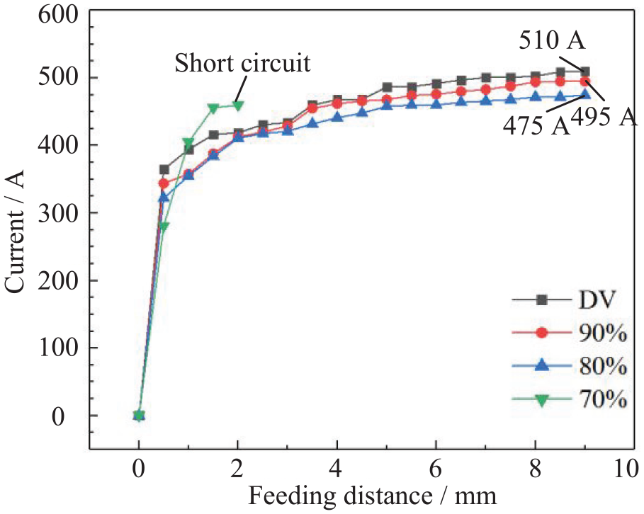
Machining current under different voltage conditions.
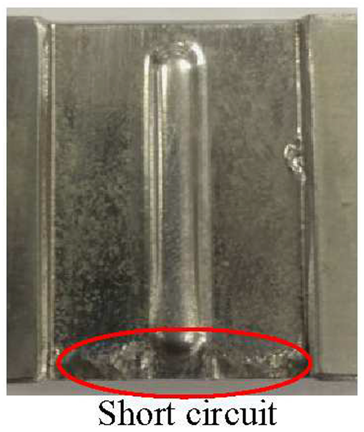
Blade machined under 70% duty cycle.
Machining accuracy
To evaluate the machining accuracy, the taper of the machined blades was measured. The middle section of a machined blade was used as the detection section, as shown in Figure 14, and cross-sectional photographs of blades machined under different voltage conditions were obtained (Figure 15). In Figures 14 and 15, samples I–III are blades machined under DV and 90% and 80% duty cycle, respectively.
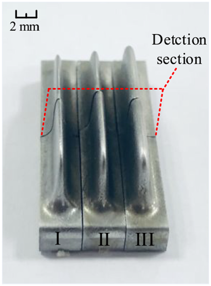
Detection section of machined blades.
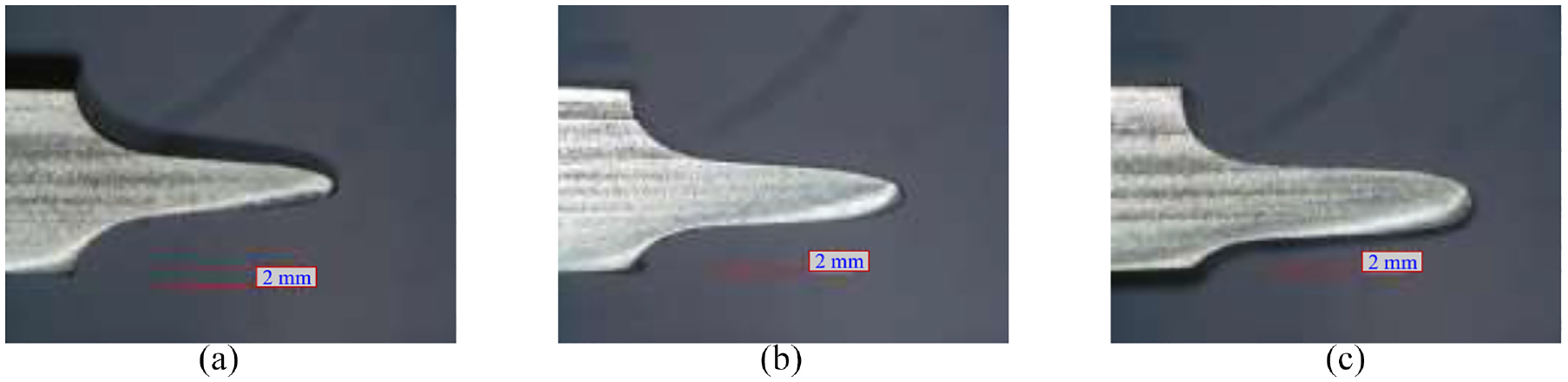
Photographs of blades machined under different voltage conditions: (a) sample I, (b) sample II, and (c) sample III.
The taper angles of the machined blades were measured using a coordinate measuring instrument (GLOBAL Advantage; Hexagon, Sweden), these being 7.784°, 6.278°, and 5.191° for samples I (DV), II (90% duty cycle), and III (80% duty cycle), respectively. Obviously, compared with the blade machining accuracy under DV, that under PV was much better, and the machining accuracy improved further with decreasing duty cycle.
The experimental results show the same trends as those of the simulation results. With decreasing duty cycle, the machined blade became higher and the machining accuracy improved. For the machined blades, less stray corrosion was suffered under a smaller duty cycle. Based on the ηω–i curve of Inconel 625 (Figure 2), at low current density, small fluctuations can cause a large change in current efficiency, resulting in a greater corrosion rate in the tip region under DV. Under the influence of various factors, the blade machining accuracy increased with decreasing duty cycle.
Surface quality
The three-dimensional surface-profile morphologies and surface roughness of machined blades (Figure 16) were measured using a three-dimensional optical profiler (S-NEOX; Sensofar, Spain), and the microscopic morphologies of the machined blade surfaces were observed using a scanning electron microscope (S-3400N; Hitachi, Japan). Also obtained were the surface morphologies of the blade tip regions (Figure 17).
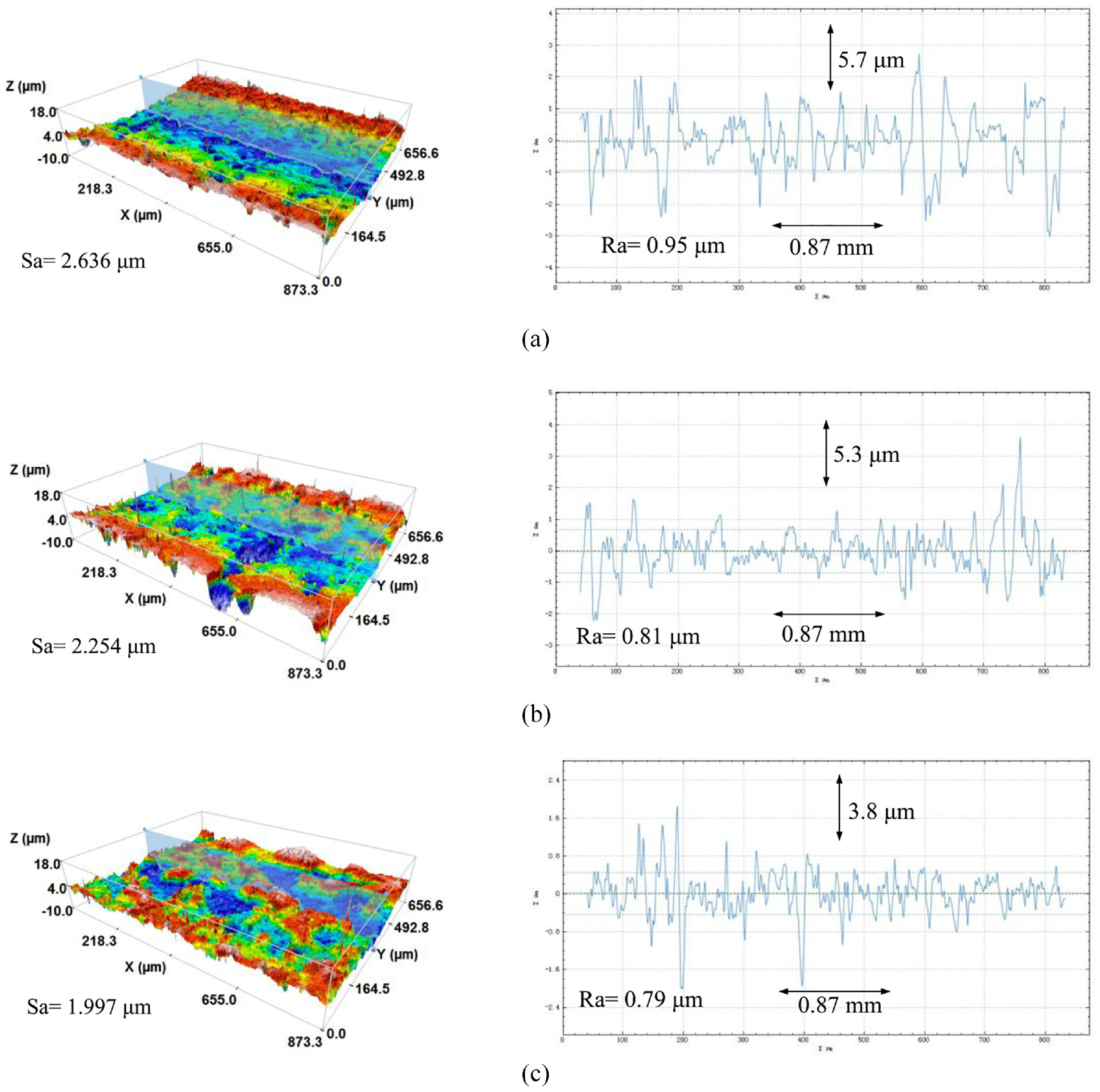
Surface morphologies and roughness curves of blades machined under different voltage conditions: (a) DV, (b) 90% duty cycle, and (c) 80% duty cycle.
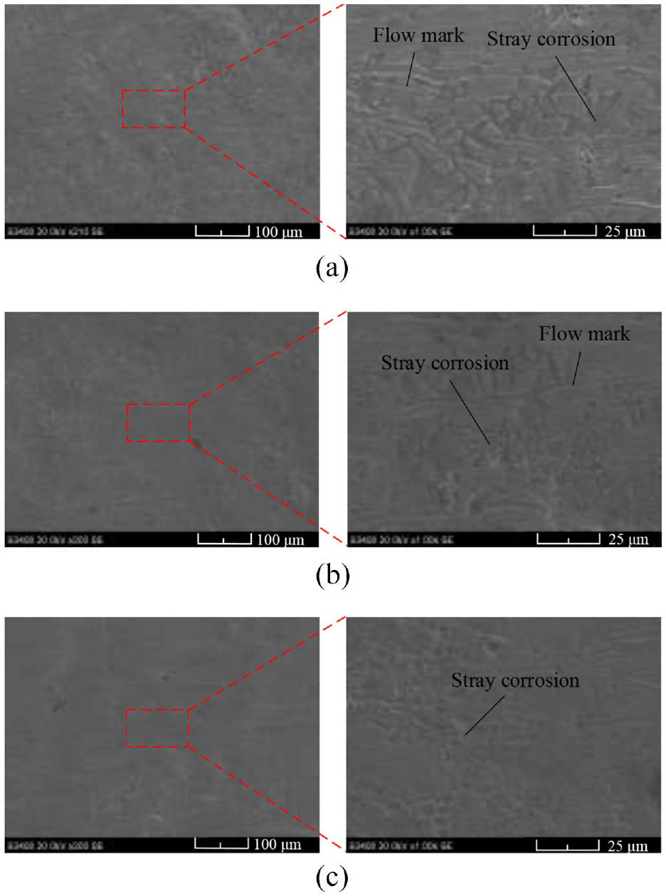
Surface microscopic morphologies of tip region for blades machined under different voltage conditions: (a) DV,(b) 90% duty cycle, and (c) 80% duty cycle.
From Figure 16, the surfaces of the machined blades were flatter under PV than under DV. The blade machined under 80% duty cycle had the best surface morphology. The surface roughness (Ra) values were 0.95, 0.81, and 0.72 µm under DV and 90% and 80% duty cycle, respectively.
From Figure 17, under DV, the machined surface showed obvious flow marks and severe stray corrosion, resulting in obvious gullies on the microscopic surface. Under 90% duty cycle, the surface became smoother and the flow marks thereon were reduced; also the degree of stray corrosion was reduced significantly. Under 80% duty cycle, there was basically no flow pattern on the surface; also, the degree of stray corrosion was very low, and only corresponding pits were formed on the surface.
With decreasing duty cycle, the surface quality improved gradually. The reduction in flow marks shows that using a pulsed voltage can improve the state of the flow field in machining. Under DV, the material corroded continuously, and bubbles and other processing by-products were generated constantly. Although the electrolyte flowed at high speed in the machining gap, the machined by-products still adhered to the blade surface. That may have caused the electrolyte in the machining area to not be updated effectively, thereby forming the observed flow pattern. Under PV, the material was removed intermittently. In the low-level phase (0 V), the high-speed flowing electrolyte could remove the products in the processing area effectively, and the electrolyte was renewed in time. So, the flow state under PV was better than that under DV. Under the combined effects of poor flow state and severe stray corrosion, the gullies shown in Figure 17(a) formed at the grain boundaries. Under PV, the intermittent corrosion of the material meant that the state of the flow field and the stray corrosion were improved compared to those under DV. Also, with decreasing duty cycle, there was less stray corrosion and a better flow state. Thus, the surfaces shown in Figure 17(b) and (c) were formed.
Conclusions
The electrochemical characteristics and the ECTr of Inconel 625 were studied through simulations and experiments, and the results obtained under different voltage conditions were presented. The experiments verified the simulation results effectively. From the contributions in this paper, the following conclusions are drawn.
For Inconel 625, its electrochemical characteristics were measured, specifically the AP and AVEE curves. The electrochemical characteristics of Inconel 625 under 20-wt% NaNO3 solution were analyzed at 30°C.
Two-dimensional electric-field simulations of ECTr were performed under DV and PV. Through the simulations, the blade forming processes under different voltage conditions were examined, and the blade profiles and distributions of current density at different times were obtained. With decreasing duty cycle, the forming accuracy improved gradually and the machined area of the blade suffered less stray corrosion.
ECTr experiments on Inconel 625 were carried out under different voltage conditions. According to the experimental results, the taper angles of blades machined under DV and 90% and 80% duty cycle were 7.784°, 6.278°, and 5.191°, respectively, and the surface roughness (Ra) values were 0.95, 0.81, and 0.72 µm, respectively. Under DV, there were obvious flow patterns and gullies on the microscopic surface. Also, with decreasing duty cycle, the stray corrosion was reduced effectively and the state of the flow field was improved. The simulation results were verified effectively. For Inconel 625, using PV can effectively reduce the stray corrosion and enhance the surface quality of blades in ECTr.
Footnotes
Declaration of conflicting interests
The author(s) declared no potential conflicts of interest with respect to the research, authorship, and/or publication of this article.
Funding
The author(s) disclosed receipt of the following financial support for the research, authorship, and/or publication of this article: This work was supported by the National Nature Science Foundation of China (91860135), the National Natural Science Foundation of China for Creative Research Groups [grant number 51921003], and the National Science and Technology Major Project [grant number 2017-VII-0004-0097].