
Abstract
Rapid tool wear is one of the major machinability aspects of nickel-based super alloys. In this article, the effect of cutting parameters on material removal rate and tool wear of a whisker ceramic insert in turning of Inconel 625 was examined. Optical microscope and scanning electron microscope were applied to measure and study tool wear mechanism. Response surface method was used to develop a mathematical model which confirmed by experimental tests. The statistical analysis done by analysis of variance showed that depth of cut is the most effective factor on the tool wear. Experiments showed that increment of feed rate had an insignificant effect on the progress of flank wear, and it is an important controlling factor when material removal rate is considered as a desired output. Finally, optimized cutting condition is presented in this work.
Introduction
Nickel-based super alloys known as difficult-to-cut materials are widely used in heat-resistant mechanical components. Having some considerable characteristics, namely, creep, fatigue and oxidation resistance, caused that these alloys to be applicable in aerospace field. 1 However, temperature in machining of these alloys exceeds over 540 °C. 2 Moreover, machining of them commonly followed by some difficulties due to their rapid strain hardening, high strength as well as poor thermal conductivity which results a faster tool wear progress.3,4 In the common way to avoid rapid tool wear during machining of nickel-based alloys such as Inconel materials, lower cutting speed is chosen to reduce the temperature in the cutting zone. It could be a right way but it is in contradiction with the aims of advanced manufacturing technology. Thus, the ceramic tool which has the qualities such as high wear resistance and low thermal expansion in high temperatures is generally used. 5 Regarding this matter, a number of attempts have been made to analyze various aspects of machinability in turning of Inconel alloys when using ceramic tools.
Li et al. 6 tried to optimize the operation with regard to tool wear mechanism during turning of Inconel 718 in high-speed method. To perform their experimental tests, they utilized three ceramic tools with various geometries. At the end, it was reported that round type of ceramic tool has the best performance in high-speed machining of Inconel 718. Another work based on the analysis of tool wear mechanism was studied by Altin et al. 7 The workpiece material was Inconel 718. Moreover, the silicon nitrite–based and whisker reinforced ceramic inserts with two different types of geometries were used. As a result, it was noted that flank and crater wear for RNGN type and flank and notch wear for SNMG type of inserts showed the most domination in the wear of ceramic tools. Narutaki et al. 8 investigated on the performance of SiC whisker reinforced alumina and TiC added alumina ceramic tools in high-speed turning of Inconel 718. After running the experiments, they stated that the SiC whisker alumina tool had the least notch wear at the cutting speed under 300 m/min, while in the higher range of cutting speed the second tool indicated better performance considering the selected wear criterion. Ezugwu et al. 9 investigated the effect of various coolant supply pressures on notch wear, cutting force and surface roughness. They used a round shape of ceramic tool in turning of Inconel 718. As a result of this process, it was reported that 15 MPa coolant supply pressure prevented the tool against the excessive notch wear, while 20.3 MPa and more than this value did not show any improvement. In addition, the increase of this parameter resulted in the reduction of cutting force.
In addition to the works studied on Inconel 718, the few available studies on Inconel 625 in all aspects of machinability are reviewed. Venkatesan et al. 10 optimized cutting parameters to achieve high quality of surface finish together with the lower cutting force (under dry cutting conditions) using coated carbide inserts (PVD AlTiN). For this purpose, the analysis of variance (ANOVA), and regression analysis were utilized based on Taguchi’s L9 orthogonal array. Finally, they found that the aspects selected for determination of machinability are mostly affected by feed rate compared to other ones. In another research, Marimuthu and Baskaran 11 developed a model to obtain high quality of surface finish and high material removal rate (MRR) by implementing ANOVA. They used TiAlN-coated carbide tool for turning of Inconel 625 under dry cutting conditions.
As it was reviewed in some recent attempts focusing on the machining of Inconel super alloys, no studies are reported on the tool wear (specially the ceramic tools) in turning of Inconel 625. Therefore, the aim of this work is to investigate the effective cutting parameters on the MRR and tool wear during turning of Inconel 625 using ANOVA. Besides, the optimized parameters are also presented.
Response surface method and experimental design
Response surface method is an empirical modeling on the basis of polynomial and linear equation which is established by a relationship between input value of variables and response values measured in experiments. 12 The developed model is useful to respond other range of input values. However, the local validation is generally observed for the response of developed model.13,14
In this study, RSM was used to detect and model the effect of cutting parameters on the tool wear and MRR. Cutting speed (Vc), feed rate (f) and depth of cut (ap) were chosen as the independent variables, and the desired response was the minimum flank wear and maximum MRR. The general equation of polynomial response is given as follows
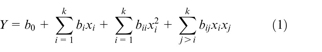
where xi and xj are independent variables (depth of cut, cutting speed and feed rate), and b0 is constant, bi, bii and bij represent the coefficients of linear, quadratic and cross-product terms, respectively. The number of variables is indicated by k and Y is the desired response.
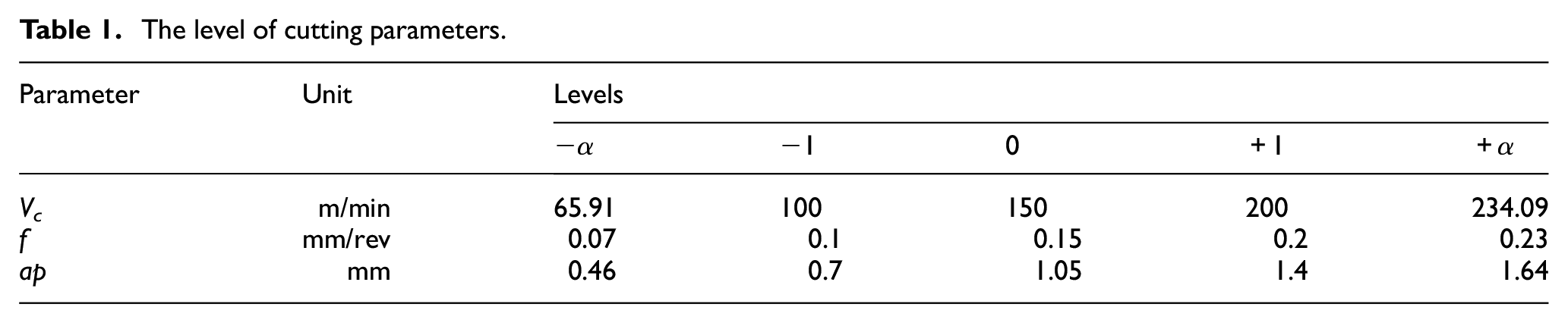
Development and fitting of second-order model require at least three different levels for each variable. Central composite design (CCD) which is a fractional factorial design with five-level facilitates the utilization of RSM for further analysis and modeling the effect of variable parameters on the flank wear and MRR. 15 Generally, a CCD comprises a 2 k factorial, 2k axial points and three to five center points. For this work, a CCD design was utilized including eight factorial points, four central points (coded level 0) and six axial points. In Table 1, ±1 is low and high levels of selected design and ±α is low and high levels of axial points. Also to obtain a rotatable design, α which is a function of k has been selected as 1.41 in coded form. Table 1 shows the cutting parameters and their values in five levels.
The level of cutting parameters.
Experimental procedure
To run the experiments, Inconel 625 super-alloy was selected as the workpiece material which widely used in the aerospace field. The finishing operation was applied on the workpiece in every level of test due to the equalization of cutting conditions. In addition, whisker reinforced alumina oxide–based ceramic insert with the round geometry and chamfer honing edge (RNGN19-CC 670) was selected from Sandvik Coromant catalogue to achieve high speeds in dry cutting condition. It should be noted that new insert was used for each cutting condition where it was used once. Repetition is carried out at the central point only to find the experiment error and how reliable it is.
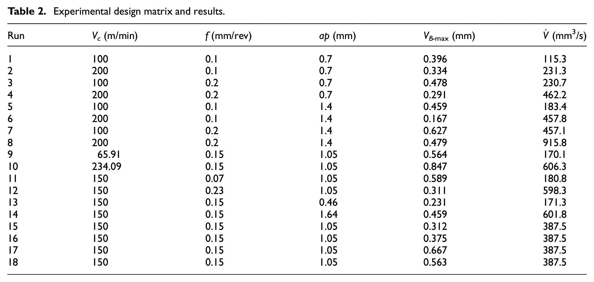
Here, the maximum flank wear in the constant cutting length of 50 mm was selected as the tool wear response. This length has been assigned by some trial and error test at the middle level of cutting conditions designed and shown in Table 2 so that value of maximum flank wear achieves VB-max = 0.6 mm considering the standard ISO 3685:1993. 16 Figure 1 shows the flank wear profile.
Experimental design matrix and results.
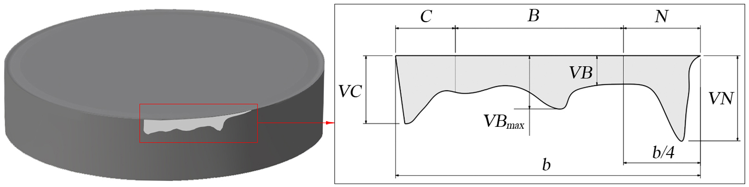
Flank wear profile.
For implementation of experimental tests, details of equipments employed and their application are given as follows:
TC35 CNC machine with transversal speed range from 1 to 3500 r/min;
LZ-8 optical microscope coupled with Win CE 5.0 used to measure flank wear after each particular test;
Ultrasonic cleaner device used to clean the tool surfaces;
XL30 scanning electron microscope (SEM) used to study wear mechanism. These instruments are shown in Figure 2.
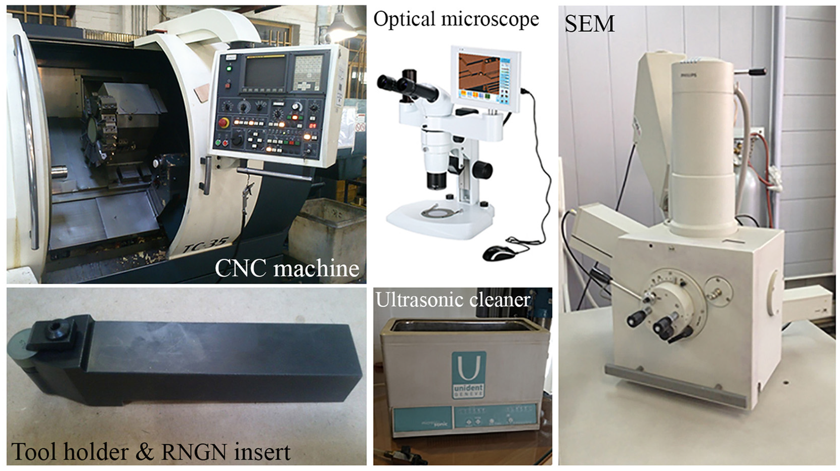
Applied instruments.
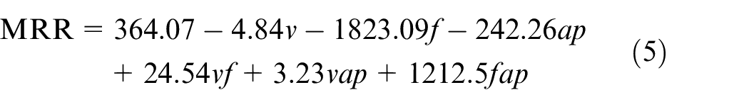
The various depth of cut, cutting speed and feed rate lead to different volume of removed material and cutting time, respectively. Hence, MRR should be considered as the second response of cutting variables, which can be calculated using equation (2), and it can be rewritten in the form of equation (3)
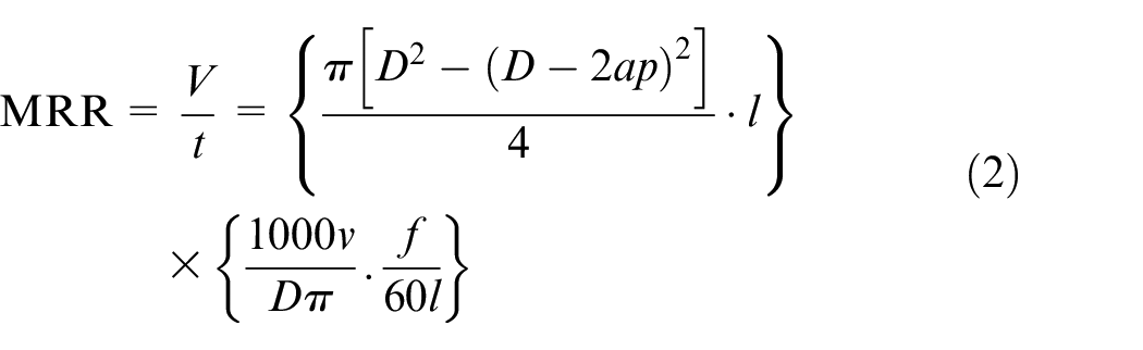
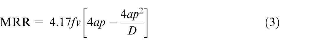
where v is the cutting speed, t is the machining time, f is the feed rate, ap is the depth of cut, l is cutting length and D is the diameter of workpiece used for each experiment, which was measured after a finishing cut in order to remove the adverse effects of previous roughing cut such as strain hardening.
Results and discussion
Developed model and analysis of adequacy
In this study, the mathematical model of flank wear is developed from obtained coefficients and independent variables (cutting parameters) using the Design Expert software. The model is given in equation (4)
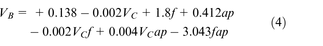
This method can also be used to generate a polynomial function to fit the MRR equation which is more compatible to the flank wear model for further optimization steps. For this purpose, the effect of workpiece diameter in equation (3) can be ignored since the value of the term
The adequacy of model developed from the responses is validated by statistical approaches such as ANOVA. Accordingly, F ratio test and ANOVA were performed to evaluate the statistical significances of the model. Table 3 clearly shows that a first-order model could be appropriate since its linear term with interaction is statistically significant. When value of “Prob. > F” for the flank wear model is less than 0.05 (i.e. p = 0.05 or 95% confidence), the obtained model is considered to be significant which is desirable. Moreover, there is no significant lack of fit for the first-order model, because its Prob > F value is higher than 0.05 and thus suggesting that this model adequately fit the data.
ANOVA table for the flank wear model
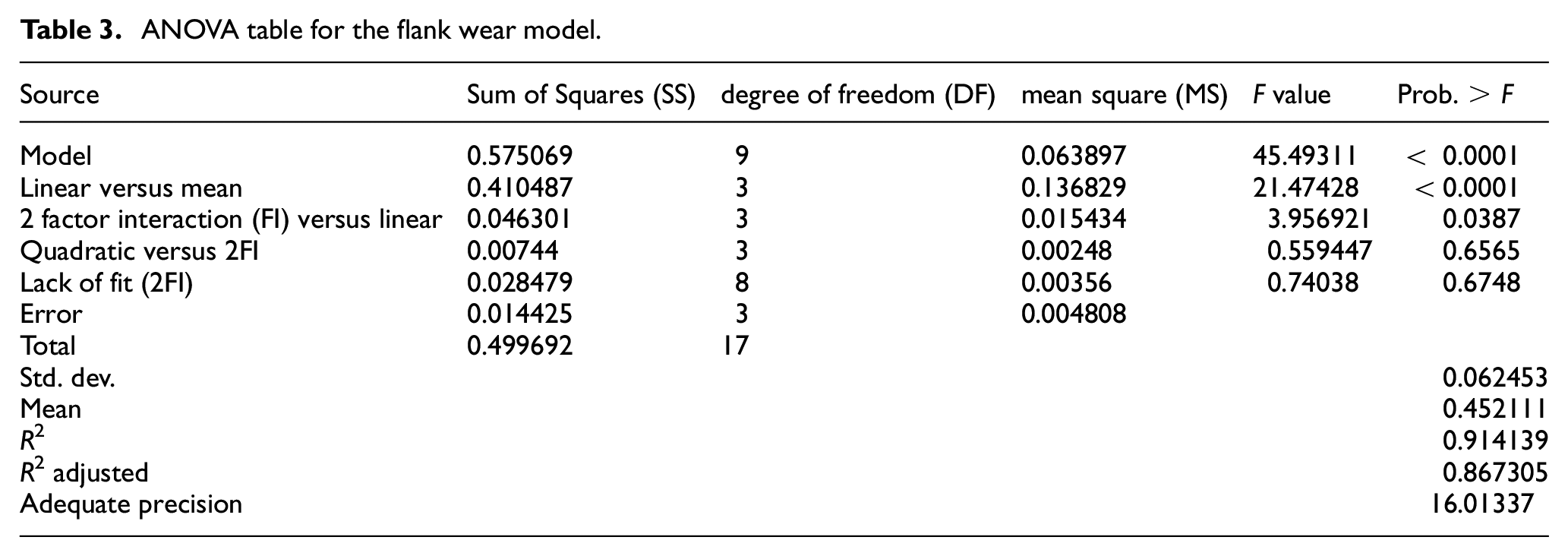
From the ANOVA table, some other performance evaluator can be observed such as R2 (the coefficient of correlation) and
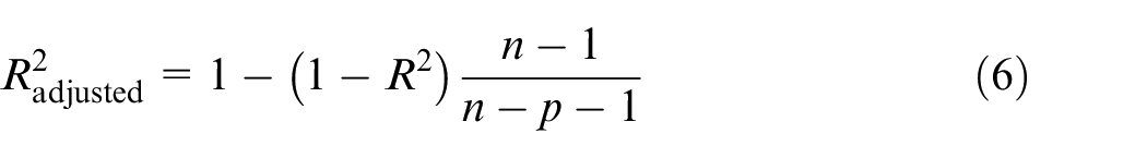
where p and n are the number of coefficients and the sample size, respectively.
In addition, the adequate precision is a measure of the contrast in predicted response about its associated error which should be above 0.06 or more. 17 Figure 3(a) and (b) depicts conformity and independency of residuals in normal probability and predicted plots, respectively. These distributions indicate the adequacy of the model.
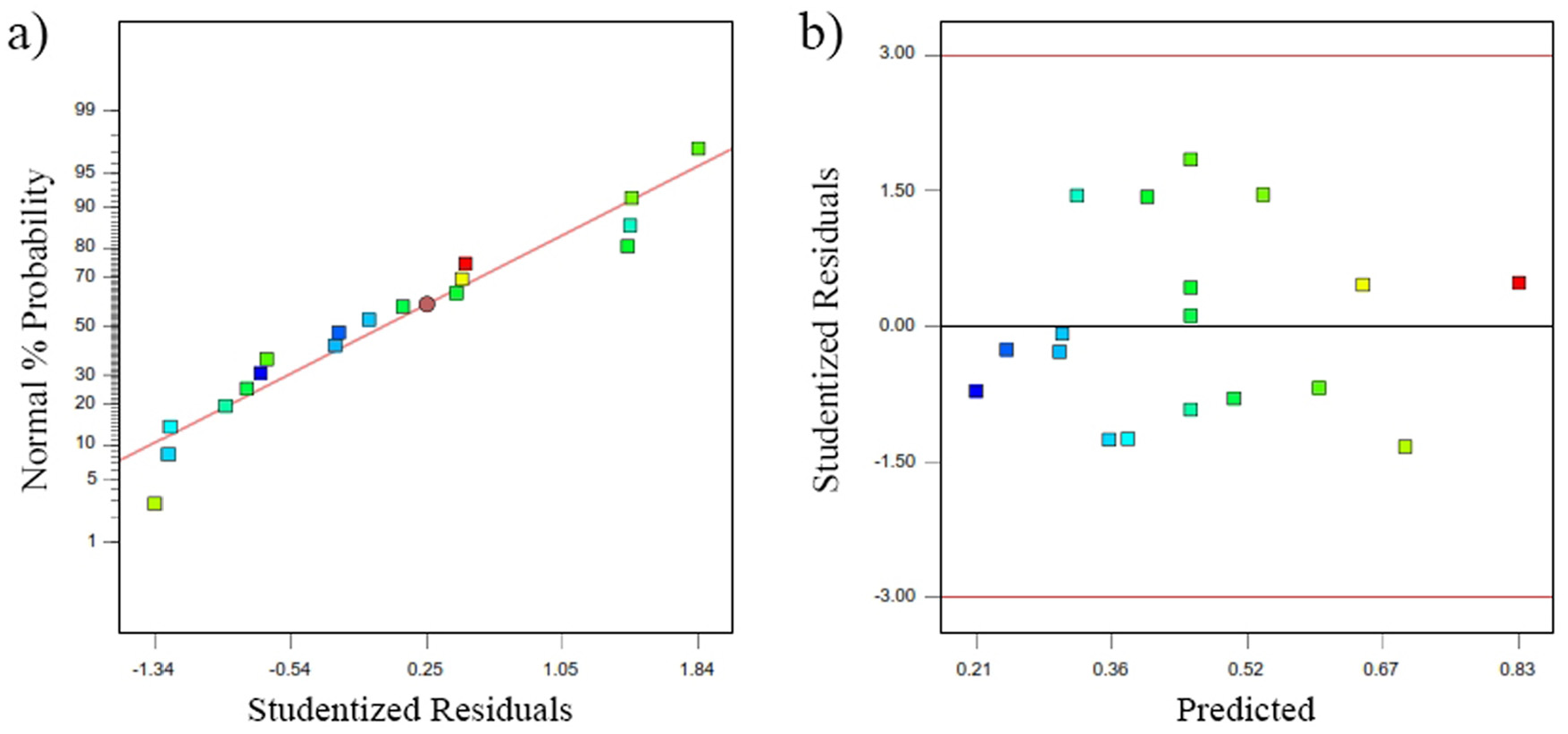
Residual diagnostic plots: (a) normal probability and (b) residuals versus predicted response.
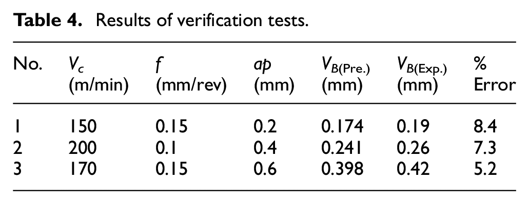
Finally, the accuracy of the developed model was verified practically by three additional experimental tests that were conducted and compared with predicted values. In respect of equation (7), the results show nearly good agreement between selected factors (Table 4)
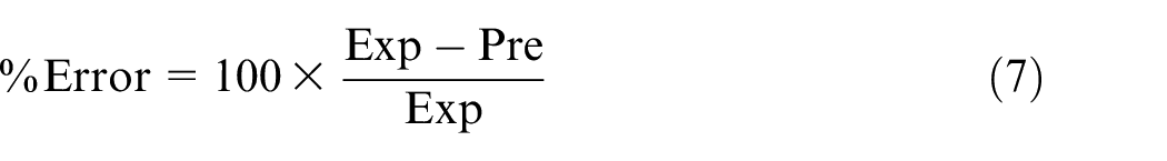
Results of verification tests.
Effect of machining parameters on the tool wear
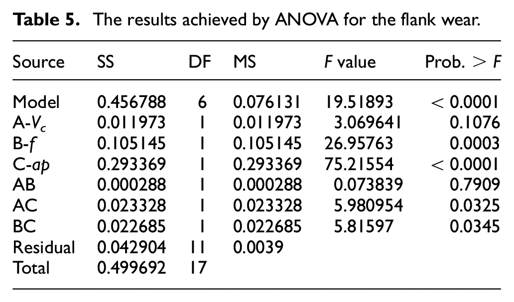
The results of ANOVA achieved from the experimental outcomes have been used to clarify the relevant effects of cutting parameters with the flank wear. Regarding the analysis, the results should be considered when the value of Prob. > F is less than 0.05. As specified, aside from the interaction of cutting speed and depth of cut, the linear value of feed rate and depth of cut with their interaction is significant (Table 5), since these interactions can describe the main influence of cutting parameters on the tool wear. Although the Prob. > F value of cutting speed is higher than 0.05, an increase in the cutting speed leads to higher flank wear due to increase in cutting temperature. However, high resistance of ceramic tools in elevated temperatures resulted into the insignificancy of cutting speed when compared to other parameters.
The results achieved by ANOVA for the flank wear.
Accordingly, Figure 4 shows that the size of flank wear decreases with increment of feed rate in both high and low levels of depth of cut. However, the interaction effect of cutting speed and feed rate is insignificant suggesting that increment of feed rate could not make a significant change on the temperature of cutting system in the selected feed rate since the cutting temperature is very high at the current cutting speed, much higher than the temperature called optimum temperature by Astakhov. 18 Based on the research carried out by Silin, 19 optimum cutting temperature in nickel-based alloys obtain at a cutting speed around 24 m/min using carbide tools, while much higher speeds were utilized in this work using ceramic tool which is able to take elevated temperatures. Therefore, small change of temperature by increment of feed rate could not be an effective factor to accelerate the flank wear. However, cold working which is very active phenomena in machining of nickel-based alloys could play a very important role in the flank wear propagation.20,21 By utilization of high levels of feed rates, the effect of hard transient surface formed on the previous tool pass and hardened by cold working can be reduced. This means that uncut chip thickness (t1) is greater than the depth of cold working (dcw), and major cutting edge cuts the original material (Figure 5) where its hardness is less than the work hardening layer. 22
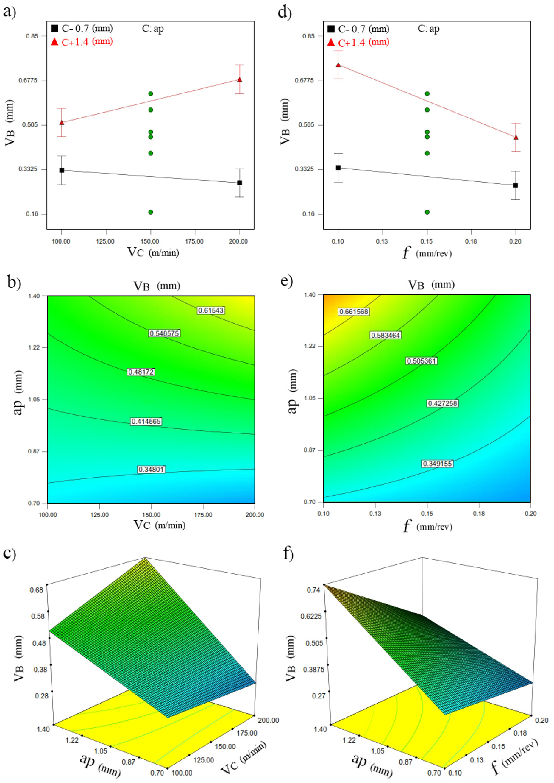
The variations in size of the flank wear in different interaction of cutting parameters: (a), (b) and (c) are related to Vc versus ap, and (d), (e) and (f) are related to f versus ap.
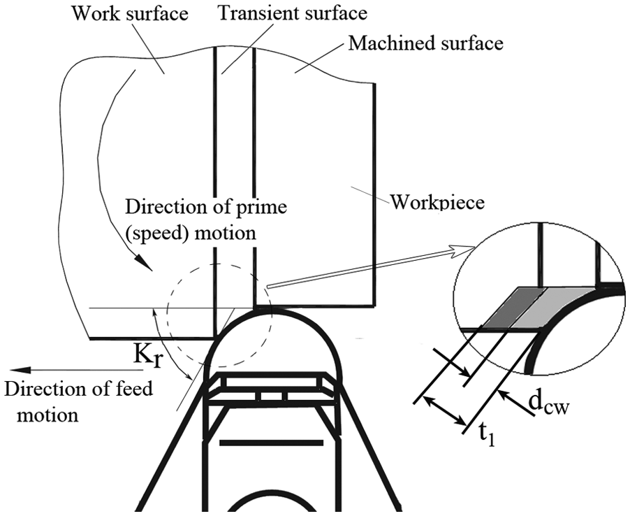
Entering angle and transient surface: t1: uncut chip thickness and dcw: depth of cold working.
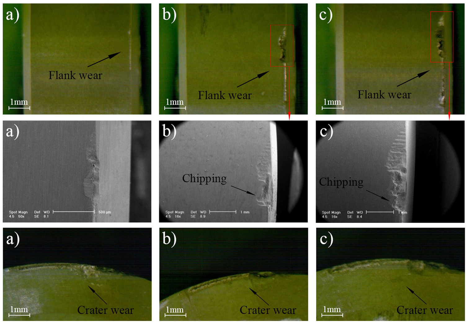
As it can be seen in Figures 6 and 7, flank and crater wear are illustrated by optical and SEM images at different depth of cuts and feed rates, respectively. Accordingly, the both flank and crater wear increase with the increase in depth of cut in such a condition that other cutting parameters are constant. Furthermore, the chipping happened, gradually, with the increase in depth of cut. Chipping and consequently notching at the severe cutting condition is a very common wear mechanism in machining of hard materials, at the high depth of cut particularly. However, this can be moderated using small entering angle. In inserts with round geometry, entering angle is a function of cutting depth and insert diameter (iC) (see equation (8)). Therefore, the gentle entrance of insert to the work material at the small entering angles tends to become an impact entrance by increasing the depth of cut which causes to chipping in the brittle material of ceramic inserts.
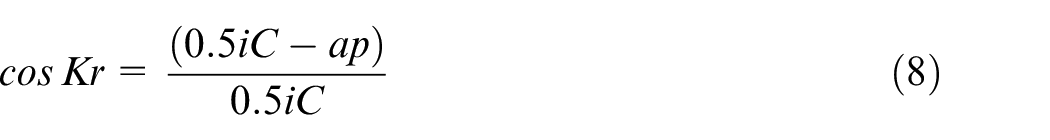
SEM and optical microscope images of flank and crater wear at different depth of cuts (mm): (a) ap = 0.46, (b) ap = 1.05 and (c) ap = 1.64 (f = 0.15 mm/rev, Vc = 150 m/min).
SEM and optical microscope images of flank and crater wear at different feed rates (mm/rev): (a) f = 0.07, (b) f = 0.23 (ap = 1.05 mm, VC = 150 m/min).
Optimization of cutting parameters
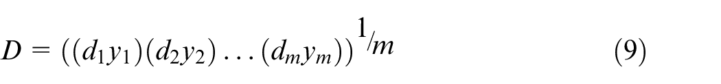
In this study to optimize cutting parameters, Design Expert software was employed which is established based on the popular desirability approach represented by Derringer and Suich. 23 This method is exerted to optimize a process with consideration of selected criteria that is defined with respect to the desired objective. In accordance with equation (9), to reach the most desirable response value (yi), the desirability function (di(yi)) should be closer to 1 which is completed response value, where value of 0 is inverse. Furthermore, by combination of every individual desirability, the overall desirability (D) can be computed. The number of responses is shown with m
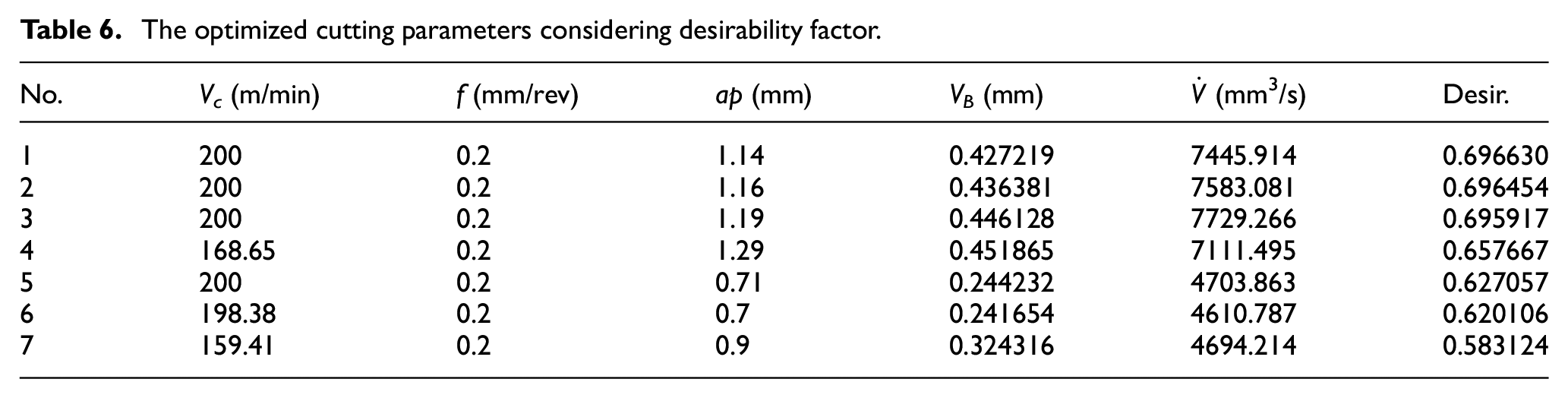
With these observations, optimal cutting parameters have been achieved when minimum flank wear with maximum MRR in equal weights was taken into account as desired condition (Table 6). Meanwhile, the point with the highest desirability is also shown in Figure 8(a) and (b) which has following cutting condition: Vc = 200 m/min, f = 0.2 mm/rev and ap = 1.14 mm.
The optimized cutting parameters considering desirability factor.
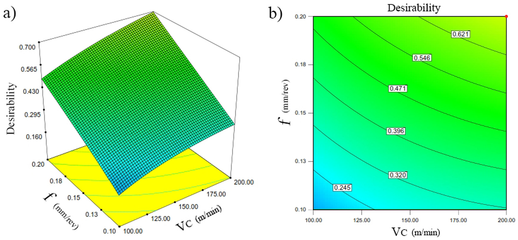
Result of overall desirability function: (a) 3D surface graph and (b) contour plot.
Conclusion
In this study, optimization of cutting parameters considering minimum flank wear and maximum MRR was carried out using ceramic tool in turning of Inconel 625. Also, the ANOVA was performed to evaluate the adequacy of predictor model developed in this article and to identify the effect of cutting parameters on tool wear. In order to study tool wear mechanism and measuring the size of flank wear, SEM and optical microscope were applied. With regard to the statistical analysis achieved by ANOVA and experimental observations, it was revealed that the size of flank wear decreases with the increase in feed rate, while the increase in depth of cut intensifies flank wear, especially, when it is associated with the increase in cutting speed. Eventually, chipping is the main wear mechanism contributing into the tool wear of ceramic tools in machining of Inconel 625 where it becomes dominant at the depth of cut. The flank wear propagation could be moderated by the increase in feed rate and decrease in depth of cut. However, the depth of cut at the middle range should be used to satisfy the MRR when equal weight is given to the tool wear.
Footnotes
Declaration of conflicting interests
The author(s) declared no potential conflicts of interest with respect to the research, authorship and/or publication of this article.
Funding
The author(s) received the following financial support for the research, authorship, and/or publication of this article: This work was supported by the Multimedia University under Mini-fund scheme (MMUI/160043) and the Production Lab of IAUN.