
Abstract
The elevated heat generation in grinding can develop high temperatures at the contact zone, which can adversely affect the surface integrity of the workpiece, especially when grinding hardened steels with conventional abrasives. Thus, the correct selection of cooling-lubrication condition is essential to avoid or attenuate any possible negative effect to workpiece surface integrity. However, the literature lacks work comparing different cutting fluid application technique (e.g. flood and minimum quantity lubrication – MQL) using the same fluid on both techniques. In this context, this work aims to contribute to the selection of cutting fluid type and its application technique for the grinding of bearing steel. Experimental trials were conducted comparing the use of semisynthetic and synthetic cutting fluids, both applied via conventional (flood) and MQL techniques. Different cutting conditions were also tested. A 24 full factorial design of experiment (DOE) was carried out with the following factors: fluid application technique, type of fluid, workspeed, and radial depth of cut. An analysis of main effects and interactions was performed for surface finish (Ra parameter) results, including a prediction model based on the analysis of variance (ANOVA). The morphology of ground surface and microhardness below machined surface were also analyzed. The results showed that the ground surface finish was strongly dependent on the cutting fluid type and its application technique combination: superior finishing was observed with the combination of semisynthetic fluid delivered via flood technique and with synthetic fluid delivered via MQL technique. From the surface morphology analysis, it was observed that the inferior lubrication capacity of synthetic fluid applied via flood condition deteriorated the surface finish and morphology. The surfaces ground with semisynthetic fluid provided, in general, lower values of Ra and lower microhardness variation. The prediction model for Ra showed a maximum error of 14% in comparison to the measured values.
Introduction
A peculiar characteristic of the grinding process is its high specific energy in comparison to other conventional machining processes, such as milling and turning. This elevated required energy for material removal is due to the great amount of plastic deformation and friction in the chip formation mechanism, which is inherent to the process and is negligible for material removal stage. 1
According to Klocke, 2 the main partition of the energy inserted into to the grinding process is transformed to heat at the grinding wheel-workpiece interface. The most part of this heat is then conducted to workpiece, especially when grinding with conventional abrasives like alumina (Al2O3), which presents low thermal conductivity at high temperatures compared to steels.3,4 Due to the low values of depth cut employed in grinding, chips with micrometer dimensions are generated, that in combination with the high wheel speeds contribute to an increase of the energy partition conducted to the workpiece, thereby increasing its temperature near the cutting interface.
Considering the grinding of hardened steels, the development of high temperatures at the contact zone due to the elevated heat generation can induce thermal damages to the workpiece, such as phase transformations, micro-cracks, tempering, re-hardened, and tensile residual stresses.5,6 According to Seidel et al., 5 the local overheat in the workpiece during mechanical processing of hardened steel can lead to a tempered zone of the martensite microstructure, which results in hardness reduction. According to Malkin and Guo, 6 the hardness reduction near machined surface is a phenomenon typically found in hardened steel subjected to grinding with conventional abrasive wheels such as alumina. It is associated to an excessive tempering of the material due to the high cutting region temperatures, and it can lead to a rejection of the ground component, even though no visible burning marks is observed. Such microhardness reduction was observed by Sridharan et al. 7 in the grinding of hardened SAE 52100 steel with alumina wheel and Ben Fathallah et al. 8 in the grinding of AISI D2 steel with CBN wheel. In this context, the use of cutting fluid in grinding of hardened steels is crucial to avoid or attenuate any negative temperature effects on the workpiece.
The cutting fluid in grinding has two main functions: directly cooling through heat dissipation at the contact zone, and lubrication by reducing friction between abrasive grits and the workpiece material, which contributes to reduce heat generation. 9 As a secondary function, the cutting fluid also contributes to removing chips from the contact zone and grinding wheel pores. 2 Nowadays, many types of cutting fluids for grinding are commercially available and their different performances regarding cooling and lubrication effects have been reported. Apart from the alternative types of cutting fluid such as gas-based coolant-lubricants (e.g. compressed air, CO2, and liquid nitrogen), the literature2,10 classifies the grinding fluids as non-water-based (or oil-based) and water-based cutting fluids. Based on ASTM E2523-1311 and ASTM D2881-19, 12 the main types of cutting fluids can be classified as straight or neat oils, emulsions, semisynthetic fluids, and synthetic fluids. According to Parthasarathy and Malkin, 13 the cutting fluids usually applied on grinding operations are emulsions and straight oils.
Straight oils, or neat oils, provide excellent lubrication capacity and corrosion resistance, but poor cooling capability. 14 Emulsions, also known as soluble oils, 15 are oil droplets (mineral or vegetable based) suspended in water containing emulsifier agents, which are responsible to increase the kinematic stability of the oil-water dispersion. Other additives such as biocides, fungicides, and extreme pressure (EP) additives are commonly used. Emulsions present a better cooling capability in comparison to neat oils, with little drawbacks regarding lubrication. However, the main disadvantage of emulsions is associated to environment and health hazards due to the chemical additives to control bacterial growth. 16 Synthetic fluids, on the other hand, consists of chemical additives with no presence of oil in their composition 17 and form a single phase mixture when dispersed in water.
Some tribological considerations of cutting fluid application in machining processes have been found in the literature. Anand et al. 18 explained that synthetic fluids present low lubricant capacity, which is the major reason that makes it not preferrable when lubrication action is crucial. The authors also point out that this characteristic encouraged the development of semisynthetic fluids, which are chemical emulsions with less oil in comparison to conventional emulsions (2%–30% – 16 ), and with some additives to reduce oil particles size. 14 Semisynthetic fluids can provide a good combination of both lubricant and cooling capacities due to the presence of oil and water. 19
In addition to the type of cutting fluid, the application technique to direct the fluid to the contact zone plays an important role in grinding. The method usually used in grinding is the conventional one, also known as flood technique, in which the cutting fluid is applied at low pressures (near atmospheric one) and flow rates higher than 5 L/min. However, due to current trends the use of techniques to reduce the consumption of cutting fluids has been increased and the minimum quantity lubrication (MQL) technique stands out. This technique consists in the application of a small quantity of cutting fluid, usually a straight oil, which is directed to contact zone with aid of compressed air, which aerosolizes the fluid providing a fine mist, a small volume, and a large surface area. Typically flow rates and compressed air pressure employed are in the range of 50–500 mL/h and 0.3–0.6 MPa, respectively.20,21
Many works have reported improvements in terms of surface finish (lower values of roughness) when grinding hardened steels with the MQL technique.22–26 According to Wang et al., 27 such improvements are attributed to the better effectiveness of MQL in delivering the cutting fluid to contact zone. It is known that an air barrier is formed around the grinding wheel due to its rotation, which difficulties the cutting fluid penetration at the contact zone.28–30 This issue is even more critical in ultra-high speed grinding (UHSG, >120 m/s). 31 The compressed air action of MQL technique contributes to overcome this barrier, thereby improving cutting fluid penetration at the grinding zone, which improves lubrication and reduce surface roughness. 27 However, it is important to mention that the type of fluid applied in the MQL technique plays an important role in its efficiency as observed by Tawakoli et al. 24 The authors evaluated several types of cutting fluid applied via MQL technique in the grinding of SAE 52100 hardened steel, including different neat oils and water-based cutting fluids. They concluded that the grindability of this material substantially increased by using straight oil. However, the authors pointed out that the use of high viscosity oils may increase cutting efforts due to the increase in the required energy in chip formation. Additionally, the MQL technique tends to favor the grinding wheel clogging.32,33
De Souza Ruzzi et al. 30 tested the use of MQL with water (1:1, 1:3, and 1:5 parts of oil per parts of water) in grinding of hardened AISI 4340 steel with CBN wheels. The trials were conducted with and without a grinding wheel cleaning system by compressed air to avoid clogging of grinding wheel pores. The authors observed that increasing the water content in MQL technique improved surface finish of ground surface (lower values of Ra), regardless to the use of the cleaning system. According to them, the dilution of the MQL oil with water decreases the viscosity of the cutting fluid, thereby improving its penetrability at the contact zone, increasing lubrication, and lowering surface roughness. Additionally, De Souza Ruzzi et al. 30 pointed out that high viscosity cutting fluids contributes to grinding wheel clogged. This consequently reduces the empty spaces of wheel pores, changing their size, shape, and distribution, which are important factors regarding cooling and lubrication conditions. 34 Furthermore, it is worth to mention that the cutting fluid capacity in removing chips from the grinding zone reduces with viscosity increase. The chips retained on grinding zone and the material adhered to abrasive grits then can lead to surface defects (smeared material). 35
Awale et al. 36 analyzed the surface finish (Ra and Rz parameters) of the hardened H13 hot die steel after grinding with white alumina wheel under different cooling-lubrication conditions, including MQL with deionized water, MQL with vegetable oil (castor oil – CO), and conventional technique (flood) with synthetic water-based cutting fluid (5%–8% concentration). The authors observed that the use of MQL with CO outperformed the flood application technique in terms of surface finish, resulting lower values of Ra and Rz, which was attributed to better lubrication property of castor oil. The MQL with deionized water resulted in higher values of Ra and Rz in comparison to flood technique.
The hardened SAE 52100 steel is the main type of material applied to the bearing industry and, as many other high-strength steel grades, it is widely submitted to grinding after heat treatment to reach the required finishing. 37 However, this class of steel is highly susceptible to thermal damages, thus the cooling-lubrication condition during grinding process is fundamental to guarantee the component’s surface integrity. According to Da Silva et al., 38 the key factors to cooling-lubrication condition selection are the cutting fluid type and its application technique. Most works that have evaluated different cutting fluid application techniques usually employ different fluids for each technique. In this context, this work sought to contribute to the selection of cutting fluid type and its application technique in grinding of hardened SAE 52100 steel with alumina (Al2O3) grinding wheel. Two different types of cutting fluid (semisynthetic and synthetic) were used for both conventional and MQL techniques, diluted and undiluted, respectively. Different cutting conditions were tested by varying workspeed (vw) and radial depth of cut (ae). The output parameters analyzed were surface finish (Ra parameter), morphology of ground surface, and microhardness below machined surface. Based on the work of Singh and Das, 39 an analysis of variance (ANOVA) was carried out based on the full factorial design of experiment (DOE) to better evaluate the effect of each factor (application technique, type of cutting fluid, vw, and ae) and their interactions on surface finish results, as well as to determine a prediction model. In general, prediction models play an important role as reference for selecting grinding conditions, and they are usually determined considering different cutting conditions (e.g. vs, vw, and ae) for a given cooling-lubrication condition, as presented by De Paiva et al., 40 De Souza Ruzzi et al., 32 and Li et al. 41 The grinding literature lacks prediction models that combine both cutting and cooling-lubrication conditions. In this sense, the present work aims to establish a mathematic model based on ANOVA analysis to predict surface roughness (Ra) from the cutting and cooling-lubrication conditions.
Experimental procedure
The grinding experiments were performed in a MELLO P-36 peripherical grinding machine, with 2.25 kW of nominal power and constant speed of 2400 rpm. A 250 mm conventional white alumina grinding wheel (38A60K6V) was used in all experiments. The workpiece material tested was SAE 52100 hardened steel (60 ± 2 HRC), with diameter of 16 mm in the grinding surface and 17 mm height.
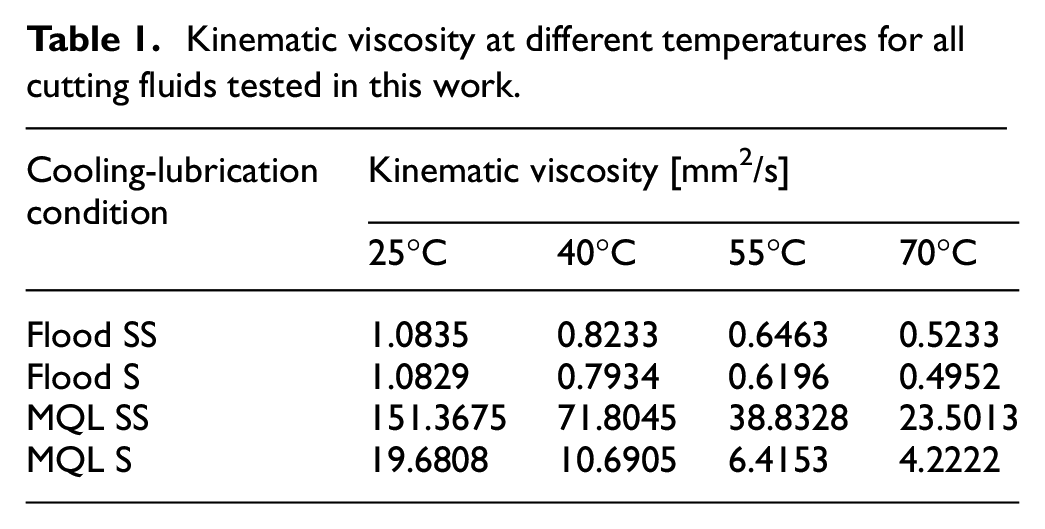
Two different types of cutting fluids were evaluated: the semisynthetic (SS) vegetable-based VASCO 7000, and the synthetic (S) GRINDEX 10, both manufactured by Blaser Swisslube. Both cutting fluids were tested using two application techniques: conventional (Flood) and minimum quantity lubrication (MQL). For the flood technique, the cutting fluids were diluted in water in 1:20 proportion (oil in water) and applied at a flow rate of 9 L/min. The refractometer index for both cutting fluid at this concentration, according to the respective manufacturer, was BRIX of 3%, which was verified before each experiment. The volume of cutting fluid prepared for flood technique trials was 50 L. For the MQL technique, the fluids were employed as received (with no dilution) and delivered at a flow rate of 150 mL/h and compressed air pressure of 0.3 MPa. Thus, four different cooling-lubrication conditions were tested, and the following terminology was adopted: Flood SS and Flood S for semisynthetic and synthetic fluid applied with conventional technique; MQL SS and MQL S for semisynthetic and synthetic fluid applied with MQL technique. For all cooling-lubrication conditions, the nozzle for cutting fluid application and its positioning were used as shown in Figure 1, chosen based on the work carried out by De Mello et al. 42 The machine, nozzle, and pump, as well as the cutting fluid reservoir were meticulously cleaned before using each different cutting fluid. The kinematic viscosity of the cutting fluids used for each cooling-lubrication condition were measured with an Anton Paar SVM 3000 viscometer, and the measurement results are shown in Table 1. As the temperature at the grinding zone can reaches high values (hundreds of degrees), the cutting fluid exposure time at these high temperature levels is quite short. Thus, the measurements of fluid viscosity from 25°C to 70°C are useful to corroborates with the process analysis.
Kinematic viscosity at different temperatures for all cutting fluids tested in this work.
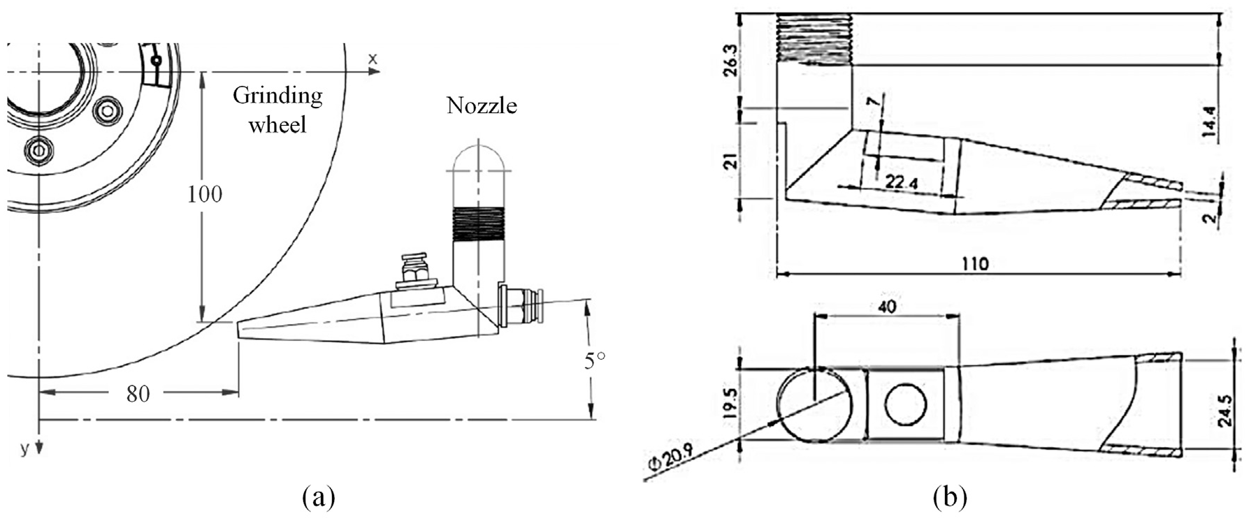
Schematic illustration detailing nozzle positioning (a) and its geometry (b).
Four different cutting conditions (C1, C2, C3, and C4) were tested by varying table speed (workspeed –vw) and radial depth of cut (ae), as shown in Table 2. These conditions were chosen based on previously work carried out on grinding of SAE 52100 hardened steel with alumina wheel.23–25,43
Cutting conditions.
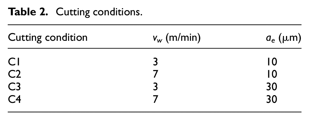
The wheel rotation was kept constant (2400 rpm) for all grinding experiments and the wheel speed (vs) was approximately 31 m/s. The grinding wheel was dressed prior each experiment with a single diamond dresser by using a dressing speed (vd) of 150 mm/min, a dressing width (bd) of 0.31 mm, and a total dressing depth of 75 μm (three passes of 25 μm). A 24 full factorial design of experiments was conducted, with one replication for the mildest and severest cutting conditions, C1 and C4, respectively. Thus, a total of twenty-four (24) trials were conducted, including eight (8) tests replications.
The output parameters analyzed were surface finish (Ra parameter) and morphology of ground surface and microhardness below machined surface. The surface finish was measured with a portable surface roughness tester Surtronic S128, manufactured by Taylor Hobson. Five measurements of Ra parameter were taken, perpendicular to grinding direction: the average and standard deviation were considered for analysis. A cut-off of 0.8 mm, five sample lengths, and Gaussian filter were used in accordance to ISO 4288. 44
The morphology of ground surfaces from the mildest (C1) and severest (C4) cutting conditions were analyzed using the scanning electron microscope (SEM) HITACHI TM 3000, with 1500 times magnification and electron voltage of 5 kV. These conditions were selected to better demonstrate the influence of the cutting condition for each cooling-lubrication condition. The microhardness below the machined surface was measured according to the hardness profile shown in Figure 2, after metallographic preparation. The microhardness measurements as shown in Figure 2(b) were replicated twice for each grinding condition, and the mean values and standard deviation were considered for analysis. The measurements taken at 3000 µm below the ground surface were considered the materials’ microhardness without the influence of grinding process. A microhardness tester SHIMADZU HMV-2 was used, with Vickers indenter and load of 980.7 mN (HV 0.1), applied for 10 s.
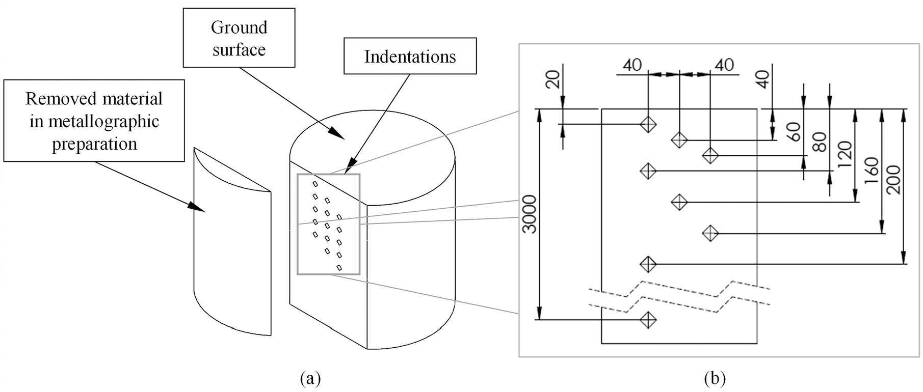
Schematic illustration of the region chosen for microhardness measurements (a), detail of microhardness profile used
Results and discussions
Surface finish
The average values of surface roughness (Ra parameter) of ground surface are shown in Figure 3 as a function of cooling-lubrication condition, for all different cutting conditions tested in this work. The best result in terms of surface finish (Ra = 0.32 µm) was observed after grinding with cutting condition C1 and cooling-lubrication condition MQL S. The grinding under the severest cutting condition (C4) and Flood S lead to the worst result in terms of surface finish (Ra = 0.62 µm). Additionally, from Figure 3, on average, the MQL technique outperformed the Flood one. To the cutting fluid type, for the Flood technique the SS outperformed the S one, while an opposite trend was observed for MQL technique.
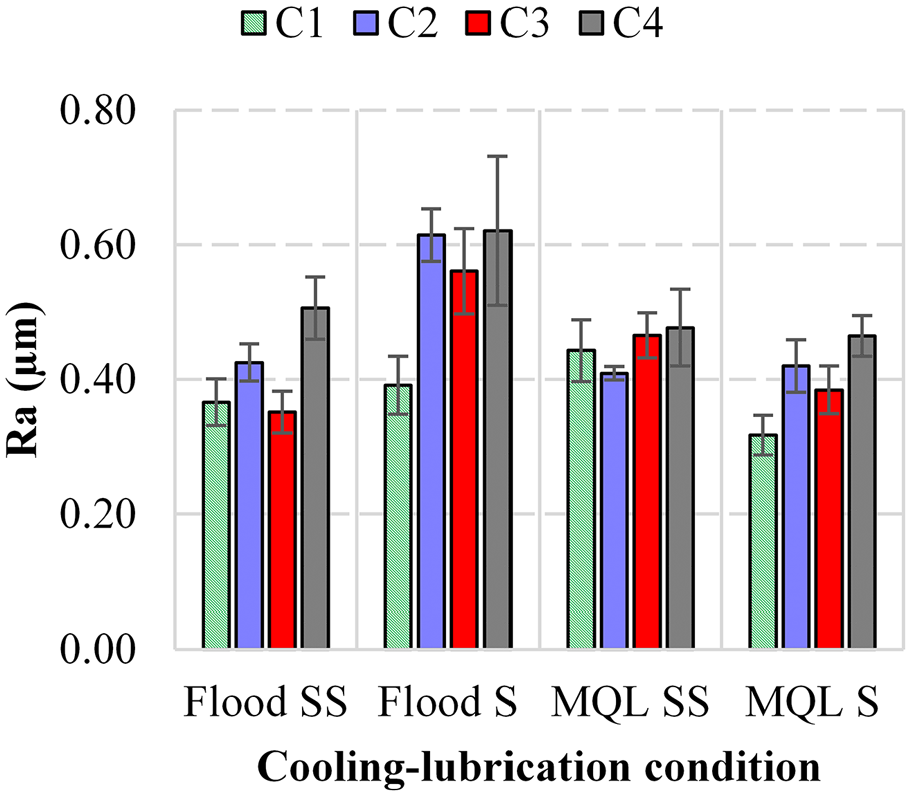
Roughness Ra versus cooling-lubrication condition.
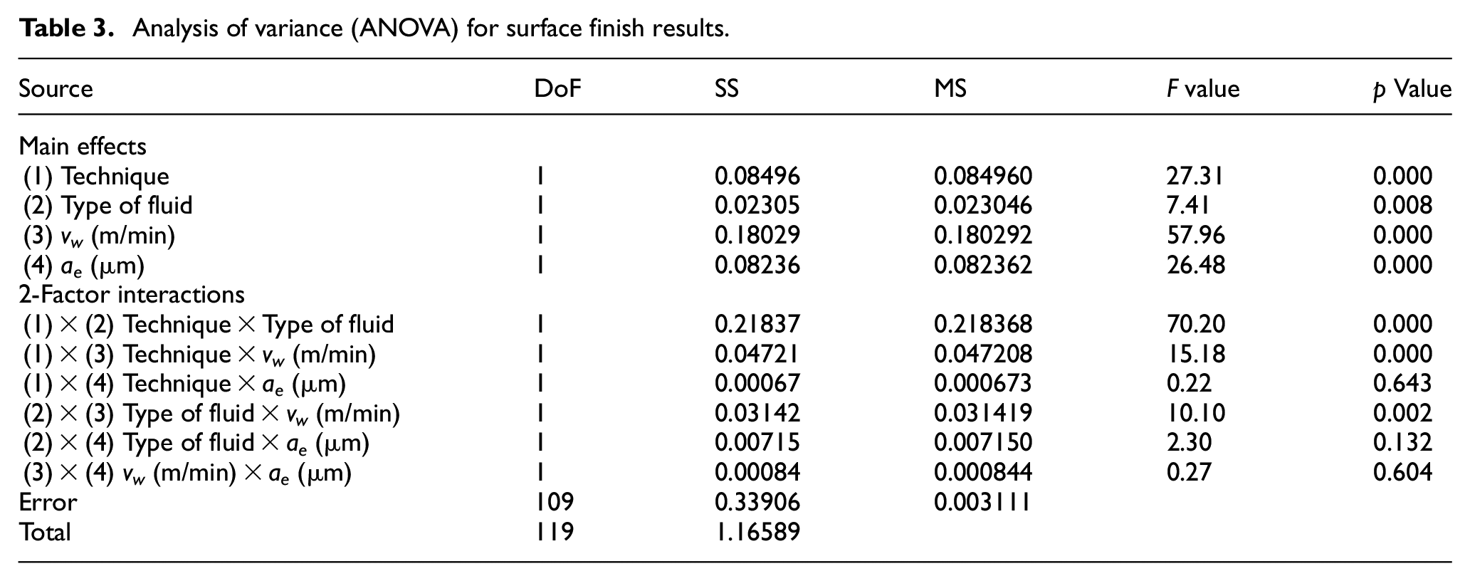
The results of the analysis of variance (ANOVA) for surface finish are presented in Table 3. From these results, it can be verified whether the factors analyzed in this work (application technique, type of fluid, vw, and ae), including their two-factor interactions, are statistically significant. Considering a confident interval of 95%, according to Table 3, the following factors and interactions were statistically significant (p values below 0.05):
Analysis of variance (ANOVA) for surface finish results.
Technique.
Type of fluid.
vw.
ae.
Technique with type of fluid.
Technique with vw.
Type of fluid with vw.
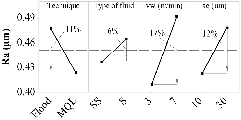
The interaction between Technique and ae, Type of fluid and ae, and vw and ae did not presented significant effect for surface finish results once their p values are higher than 0.05. The main effects for each factor are shown in Figure 4, where the values of Ra for each factor correspond to the mean value (average) of all trials carried out with the respective factor level, regardless the other factors. The percent values were calculated considering the variation between the highest and lowest value of Ra for each factor.
Main effects of several grinding factors on the surface finish results.
One notes from Figure 4 that the use of MQL technique contributed to reduce the value of Ra parameter in 11% in comparison to the grinding with Flood technique, suggesting an improvement in lubrication capacity. This is usually attributed to the higher effectiveness of MQL in delivering the cutting fluid at contact zone due to the aid of the compressed air, 27 which, compared to Flood, better overcome the air barrier that difficulties the access of the cutting fluid to the cutting zone.28–30 Similar results of lower surface roughness when grinding with MQL in comparison to Flood were also reported by Hadad et al., 25 Tawakoli et al., 24 and Awale et al. 36
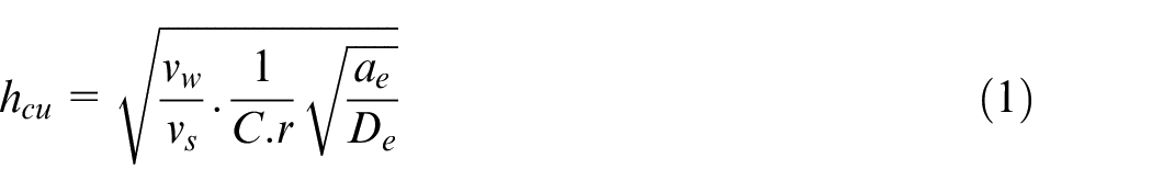
With respect to the type of cutting fluid, from Figure 4 the grinding with SS cutting fluid promoted a Ra roughness value about 6% lower in comparison to the synthetic one (S). This improvement in Ra is attributed to the difference between the properties of these cutting fluids. As presented in Table 1, the SS has higher kinematic viscosity in comparison to S, and thus a higher lubrication capacity. From Figure 4 it can also be noticed that the effect of cutting conditions on surface finish of ground surface is in accordance with the specific literature. Increasing both vw and ae result in an increase in surface roughness (Ra parameter) due to the increase in undeformed chip thickness, which adversely affects the finishing of ground surface.2,6,36 The undeformed chip thickness (hcu) can be calculated according to equation (1), where C, r, and De are the active grit density, grit point shape factor, and equivalent wheel diameter, respectively.
10
One notes from equation (1) that hcu is proportional to
The interaction graphs for the results of surface finish are shown in Figure 5. The interaction between the application technique and type of fluid (Figure 5(a)) presents curves with opposite trends, which explains the statistical significance of this interaction. This result shows that, for the conditions used in this work, the efficiency of the application technique of cutting fluid in improving surface finish of ground surface depends on the type of fluid: the semisynthetic presented better results when applied via conventional technique (flood), while the synthetic presented better results when applied via MQL technique.
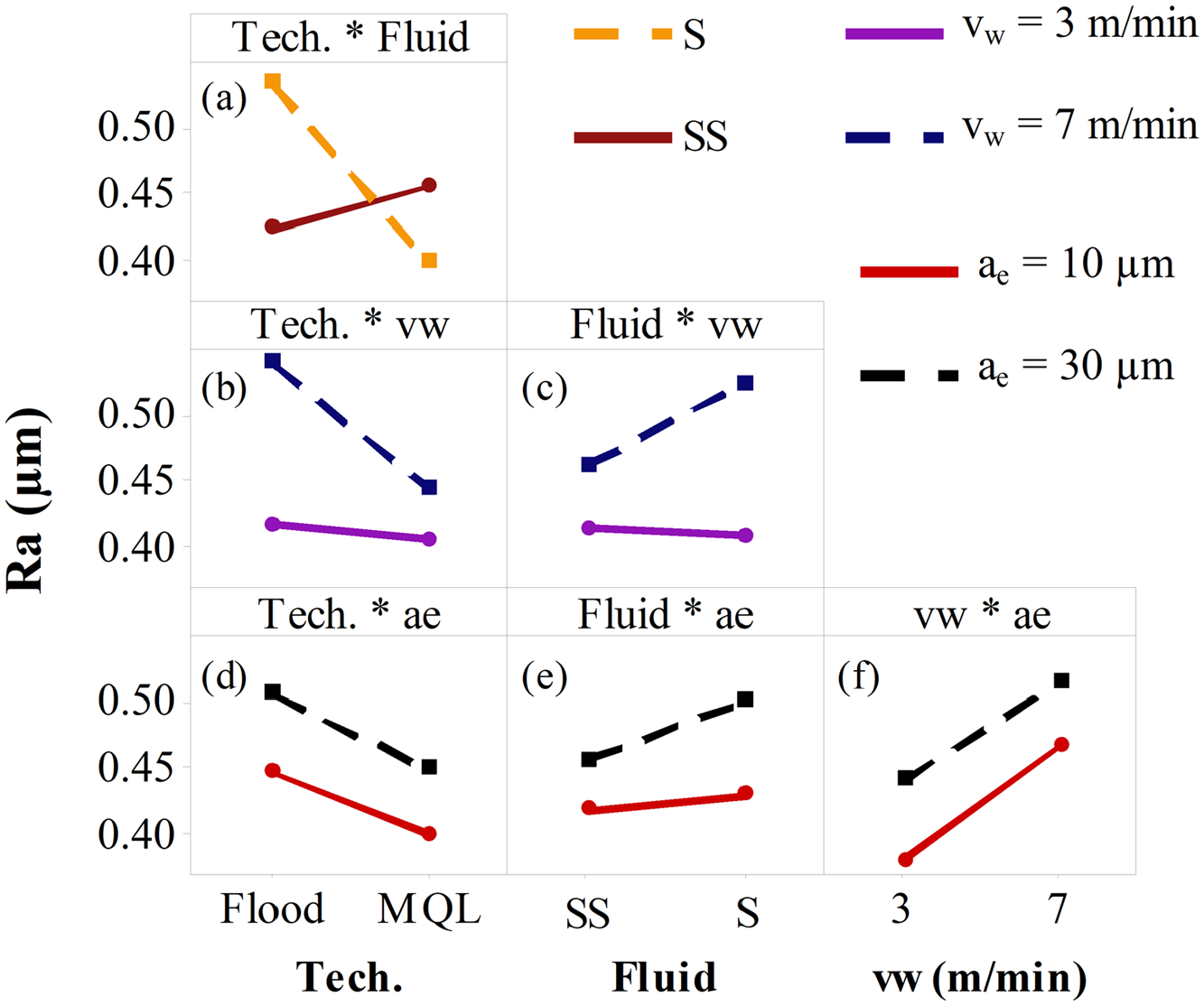
Interaction graphs for several grinding factors on the surface finish results. Significant interactions: (a–c). Not significant: (d–f).
The better performance of the synthetic fluid in comparison to the semisynthetic when using the MQL technique can be explained by the difference in their properties in terms of viscosity (10.6905 mm 2 /s and 71.8045 mm 2 /s for the synthetic and semisynthetic fluids, respectively –Table 1). According to De Souza Ruzzi et al., 30 grinding with MQL technique using high viscosity cutting fluids reduces fluid’s efficiency in removing the chips from the contact zone and grinding wheel pores, instead, it leads to grinding wheel clogging, thereby negatively affecting surface finish of ground surface. Grinding with conventional technique (flood) promotes better flushing capability when using both cutting fluids, since water was added in both for this technique, thereby resulting in much lower viscosity in compared to the undiluted oils. In this case, the higher viscosity of Flood SS in comparison to Flood S at high temperatures (over 5% for 70°C –Table 1) contributes to increase lubrication at the contact zone, improving tribological conditions that favors chip formation and reducing surface roughness (Ra parameter).
From Figure 5, in general, grinding with MQL technique and SS fluid contributed to reduce Ra especially when using vw = 7 m/min (Figure 5(b) and (c)). This explains the statistical significance of these interactions and indicates that, when high values of vw are used, the lubrication capacity of the cooling-lubrication condition is the major factor to improve surface quality in grinding of SAE 52100 hardened steel.
The regression equation of ANOVA’s model for Ra values is shown in equation (2), where the values of the factors must be inputted in coding form as shown in Table 4. The predicted values of Ra are compared to the measured values in Figure 6, where it can be noticed that the model fitted well considering the conditions of this work, presenting a maximum error of 14% for the grinding condition Flood SS C3.
Factors and coding form for application of equation (2).
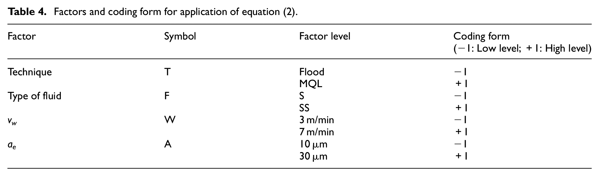
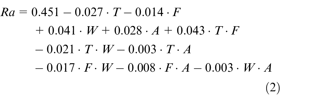
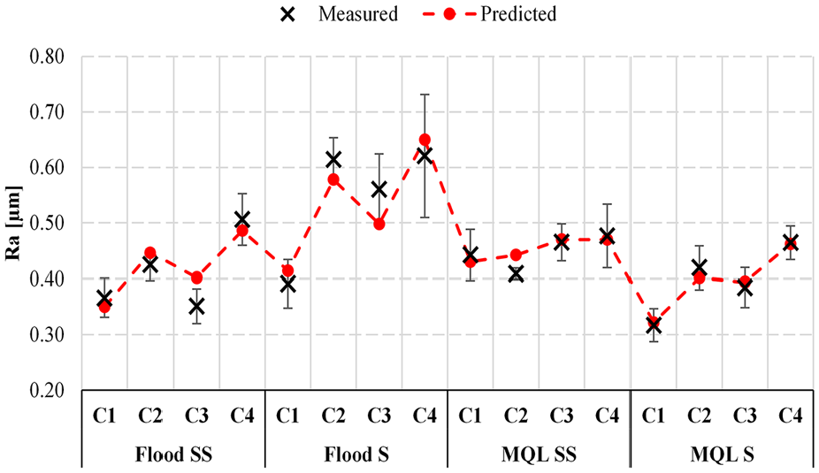
Comparison between predicted and measured Ra values.
Surface morphology
The morphology of machined surfaces after grinding with the mildest and severest cutting conditions, C1 and C4, respectively, are shown in Figure 7, for all the cooling-lubrication conditions tested in this work. The values of Ra roughness are also shown according to Figure 3; the best result is for condition MQL S – C1 [Figure 7(g) – Ra = 0.32 μm].
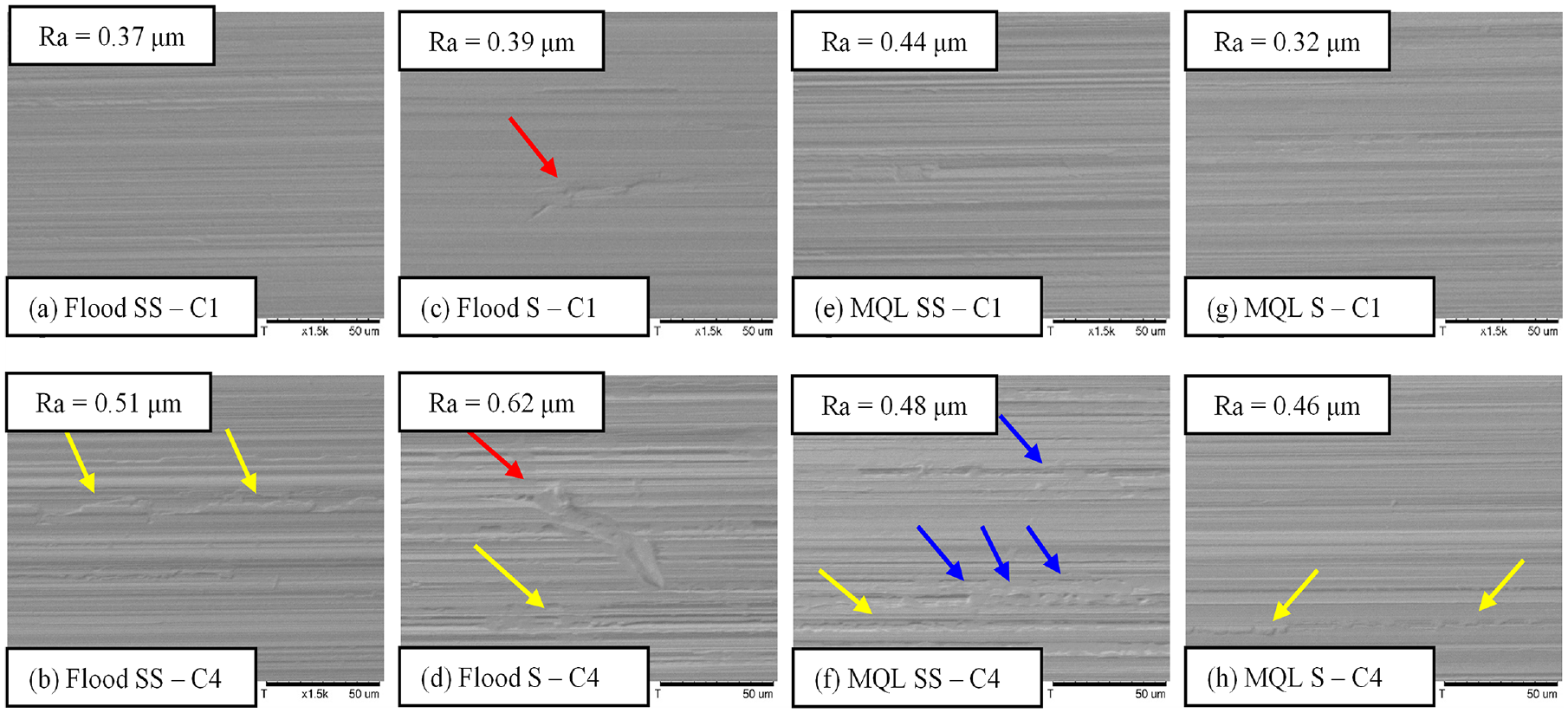
Surface morphology of ground surfaces: (a) Flood SS - C1, (b) Flood SS - C4, (c) Flood S - C1, (d) Flood S - C4, (e) MQL SS - C1, (f) MQL SS - C4, (g) MQL S - C1, (h) MQL S - C4..
One notes from Figure 7 that more evidence of intense plastic deformation was present on the surfaces ground with the cutting conditions C4 as highlighted by the yellow arrows in Figure 7(b), (d) and (h). Similar results were found by De Souza Ruzzi et al. 45 in the grinding of AISI 4340 hardened steel with Al2O3 wheel. According to the authors, the higher the undeformed chip thickness, the higher the contact area between the abrasive grits and the workpiece, which will lead to a lower shearing stress. This favors micro-ploughing wear mechanism, thereby increasing the amount of material that experienced plastic deformation only, without chip formation.
With respect to the cooling-lubrication conditions, one notes from Figure 7 that the surfaces ground using Flood S, Figure 7(c) and (d), exhibited some discontinuities on the grooves formed by the abrasive grits action, as indicated by the red arrows. This surface defect suggests an insufficient lubrication at contact zone, which corroborates with surface finish results.
Comparing the morphology of machined surfaces when grinding with MQL technique (Figure 7(e)–(h)) with those ground with Flood (Figure 7(a)–(d)), it can be noticed that the application technique played influence on the surface quality of workpiece when grinding under the severest cutting condition only. The use of Flood technique had severe surface defects for both SS and S fluids, while MQL technique showed defects for SS fluid only (indicated by the blue arrows). Thus, it can be inferred that the MQL technique presented, in general, better results in terms of surface morphology in comparison to Flood. Furthermore, surface defects observed when grinding with MQL SS indicate that this cooling-lubrication condition in fact contributed to grinding wheel clogging as discussed in surface finish results. The presence of chips at contact zone and/or at wheel pores diminishes material removal efficiency, 32 thereby contributing for micro-ploughing and material being welded or smeared onto the workpiece surface (material adhesion), deteriorating surface morphology as observed in Figure 7(f).
Microhardness below machined surface
The microhardness below machined surface for all the conditions tested in this work are shown in Figure 8. The dotted line represents the bulk microhardness at 3000 µm below machined surface (801 HV 0.1). From Figure 8 can be noticed that the grinding using the semisynthetic fluid (Figure 8(a) and (c)) did not promote significant alterations on the microhardness below the machined surface, irrespective to application technique and cutting conditions employed. In contrast, the use of the synthetic fluid resulted in significant reduction in microhardness below the machined surface, as it can be seen in Figure 8(b) and (d), especially for cutting condition C4.
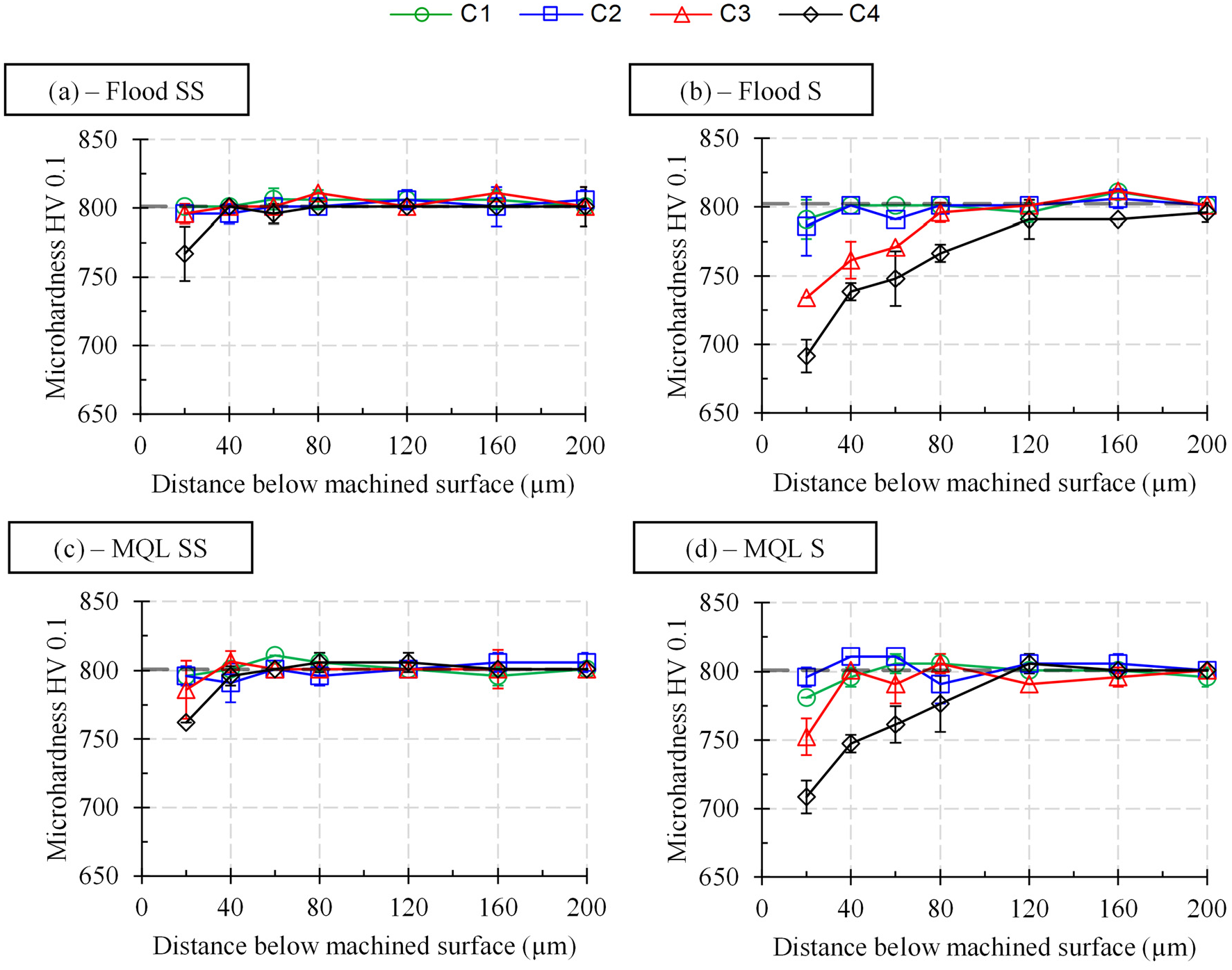
Microhardness below machined surface for the conditions tested in this work: (a) Flood SS, (b) Flood S, (c) MQL SS, (d) MQL S..
As previously mentioned, the hardness reduction near ground surface is a phenomenon typically found in hardened steels subjected to grinding, which is associated to an excessive tempering of the material in regions near abrasive grits-workpiece interface, as a consequence of the development of high cutting temperatures.6–8 In this context, the microhardness results shown in Figure 8 suggest that the heat generation at contact zone was lower when grinding with semisynthetic fluid in comparison to synthetic one, thereby attenuating negative temperature effects on workpiece (e.g. hardness reduction below machined surface). This result can be attributed to the better lubrication capacity (higher viscosity) of SS in comparison to S, which reduces the friction between the abrasive grits and workpiece at contact zone, resulting in less heat generation. 9
Regarding the cutting fluid application technique, from Figure 8 one notes that grinding with SS fluid delivered with both Flood and MQL techniques provided similar results. For the grinding using the S fluid, the MQL slight outperformed Flood technique (lower microhardness reduction). This result is another evidence of the poorer lubrication capacity of the cooling-lubrication condition Flood S, which corroborates previous discussions. Furthermore, it also shows that the MQL technique is in fact a viable environmentally friendly alternative to Flood technique, since it presented similar/better results in terms of surface integrity, even though using a flow rate of cutting fluid 3600 times lower.
With respect to the influence of the cutting conditions on the microhardness results, it can be noticed from Figure 8 that only the grinding using the severest cutting conditions (C3 and C4) promoted some hardness reduction below the machined surface. Higher material removal rates increase heat generation, thereby leading to the development of higher temperatures at contact zone. This contributes to increase the negative temperature effects on workpiece, either by increasing the heat affected zone or the hardness reduction below machined surface.2,6–8
Conclusions
Considering the results found after grinding with semisynthetic and synthetic fluids, both applied via conventional (flood) and MQL techniques under different cutting conditions, the following conclusions can be drawn:
The combination between cutting fluid type and application technique strongly affected surface roughness. Best results (lower values of Ra) when using semisynthetic fluid were observed for conventional technique (flood). When using synthetic fluid, best results were found for MQL technique.
The prediction model for Ra roughness presented a maximum error of 14% in comparison to measured values of Ra, showing therefore a good fit considering the grinding conditions employed in this work.
The ground surfaces morphology indicated an insufficient lubrication capacity of the synthetic fluid applied via conventional technique (Flood S), and material from the wheel adhering to the work surface for grinding with the semisynthetic fluid applied via MQL technique (MQL SS), which corroborates with surface finish results.
Grinding with the semisynthetic fluid promoted better results in terms of microhardness below machined surface (lower microhardness reduction), indicating less heat generation in comparison to the grinding with synthetic fluid.
Grinding with the semisynthetic cutting fluid applied by the conventional technique and also by the MQL technique were the cooling lubrication conditions that resulted, overall, in better surface finish and lower microhardness reduction close to machined surface.
Footnotes
Appendix
Acknowledgements
The authors are grateful to the Conselho Nacional de Desenvolvimento Científico e Tecnológico (CNPq), the Fundação de Amparo à Pesquisa do Estado de Minas Gerais (FAPEMIG), and the Coordenação de Aperfeiçoamento de Pessoal de Nível Superior (CAPES Proex). The authors also acknowledge Blaser Swisslube and Saint-Gobain Abrasives by supplying the cutting fluids and abrasive grinding wheels, respectively.
Declaration of conflicting interests
The author(s) declared no potential conflicts of interest with respect to the research, authorship, and/or publication of this article.
Funding
The author(s) disclosed receipt of the following financial support for the research, authorship, and/or publication of this article: This work was supported by the Conselho Nacional de Desenvolvimento Científico e Tecnológico (CNPq) [grant numbers 311337/2016-3, 426018/2018-4, 140320/2016-4, 141472/2017-0]; the Fundação de Amparo à Pesquisa do Estado de Minas Gerais (FAPEMIG) [process number APQ-01119-16].