
Abstract
Selective laser melting (SLM) is an important method in additive manufacturing. SLM has obvious advantages for the fabrication of metal parts with complex structure that cannot be processed directly and are manufactured in relatively low amounts. However, the surfaces of the SLM-formed parts contain more adhesive particles and pores than those manufactured by traditional methods, leading to the poor corrosion resistance of the parts and preventing the widespread use of SLM. To solve these problems, jet electrochemical machining and jet electrodeposition combined processing techniques were investigated for the treatment of the substrate surface in this work. Jet electrochemical machining was used to remove the surface defects of the SLM-formed parts, and the results were compared with the traditional sandblasting and sandpaper grinding surface treatment methods. Then, the nickel coating was deposited on the surface of the SLM-formed parts using jet electrodeposition to protect the surface and extend the service life of the parts. The mechanisms of the different processing techniques were analyzed, and properties such as the substrate morphology, coating morphology, corrosion resistance of the coating, and adhesion of the coating were compared. The results show that holes, adhesive particles and other defects are still present on the substrate surface after sandpaper grinding and sandblasting and affect the quality of the nickel coating. After electrochemical machining, the SLM surface defects were almost completely removed, forming a uniform microporous structure that interlocked with the nickel coating. The coating was smooth and dense and showed the best corrosion resistance and binding force. In 3.5 wt% NaCl solution, the corrosion potential reached −0.196 V, and the maximum binding force reached 35 N.
Keywords
Introduction
316L stainless steel is a typical austenitic stainless steel with good mechanical properties, high structural strength, and good corrosion resistance that is used in a wide range of applications in the aerospace and medical fields. 1 Metal powder additive manufacturing technology based on selective laser melting (SLM) provides a new approach for the integrated design and manufacturing of complex stainless steel structures. 2 The basic principle of this method is to use a laser beam to melt the metal powder layer by layer according to the predetermined scanning path and directly form the parts. Because SLM technology fabricates lightweight parts with high strength, it is applicable to many fields such as aerospace where low weight and high strength are the main objectives of equipment development. 3 In the medical field, SLM can customize the implant structure with any complex shape according to the requirements of the individual patient. 4 Therefore, SLM technology also has great prospects for use in the medical field. However, due to the quality of metal powder, process parameters, and other factors, the surfaces of the stainless steel parts formed by the SLM technology contain adhesion particles, pores, microcracks, and other defects that give rise to poor surface corrosion resistance, severely restricting the development and application of SLM technology. 5
To solve the above problems and expand the range of SLM application, it is necessary to treat the surface of the SLM-formed parts. Generally, the surfaces of SLM substrates are treated by sandpaper grinding, sandblasting, and mechanical processing. 6 In recent years, some non-traditional machining methods such as laser cleaning, EDM, and electrochemical machining have also been applied for the surface treatment of the SLM-formed parts. Ma et al. studied the improvement of surface roughness of Ti alloy after additive manufacturing by laser polishing. The results showed that the surface roughness of the samples was decreased from 5 to 1 μm by laser polishing, and the mechanical and microstructure properties are not affected. 7 Rosa et al. reduced the surface roughness of additive manufacturing samples from Ra 21 to 0.79 μm by optimizing the laser polishing process strategy. 8 K. Zakaria et al. used EDM to finish the surface of FeCuSn mixed metal materials after additive manufacturing. By adjusting the discharge time, discharge gap and voltage, the surface roughness of the sample was reduced to 2.41 μm. 9 Liu et al. used abrasive-assisted jet electrochemical machining to repair the surface of substrate obtained by laser melting deposition, reducing the roughness from 2.5 to about 0.5 μm. 10 Alrbaey et al. studied the influence of electropolishing on the surface morphology of 316L stainless steel parts after additive manufacturing, and used statistical methods to optimize the process parameters. The results show that the surface roughness of the sample is reduced to 0.5 μm after electropolishing. 11
After the surface treatment of the SLM components is completed, under some special conditions, the structural components must bear surface friction for a long time, such as when the SLM technology is used for structural topology optimization design in the interior of aircraft engines. In another example, for the use of SLM structures in marine machinery, it is necessary to ensure that they have good corrosion resistance. Therefore, to improve the service life of the SLM-formed parts, a nickel coating is usually deposited on the treated surface of the part by jet electrodeposition (JED) to protect the surface of the SLM-formed parts. 12 Since mechanical interlocking in the process of jet electrodeposition is the main bonding mechanism between the coating and the substrate, 13 the treatment of surface defects of the substrate has strongly affected the corrosion resistance, bonding strength, and other properties of the nickel coating.
Therefore, aiming at the surface defects of SLM samples and the problem of poor corrosion resistance, this paper hopes to deposit nickel coating on the surface of SLM parts after removing the surface defects through an electrochemical-electrodeposition jet combined machining method, so as to isolate the external moisture and corrosion environment and improve the service life of SLM formed parts.
Experimental
Experimental material
316L stainless steel powder with an average particle size of 30 μm was used as the experimental material, as shown in Figure 1(a). Its composition is 68.37% Fe, 17.17% Cr, 10.45% Ni, 2.22% Mo, 1.2% Mn, and 0.52% Si. The SLM process parameters were as follows: laser scanning rate of 840 mm/s, laser power of 220 W, and slice thickness of 0.2 mm. The specific forming method is: First, the 3D-CAD volume model is broken down into layers and transferred to the Selective Laser Melting machine. Subsequently, the powder material is deposited as a defined thin layer on a substrate. The geometric information of the individual layers is transmitted by laser beam to the powder bed where in the regions to contain solid material are scanned under an inert atmosphere, leaving a solid layer of the piece to be produced. After lowering the substrate by one layer thickness, the process steps are repeated until the part is finished. The formed sample is shown in Figure 1(b). After the workpiece was naturally cooled, it was cut into several pieces with the dimensions of 20 × 20 × 3 mm3 using an EDM wire-cutting machine. All of the prepared substrates were cleaned by ultrasonication and dried.
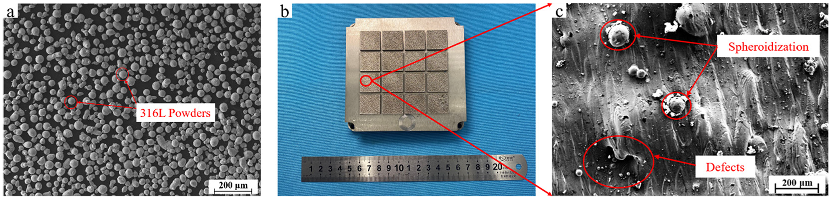
Preparation of SLM sample (a) SLM stainless steel powder (b) SLM formed sample (c) magnification of surface defects.
Experimental procedure
The experimental process is shown in Figure 2. The SLM substrate was processed by three different surface treatment methods, namely sandpaper grinding, sandblasting, and jet electrochemical machining. After that, the surface was plated with nickel coating to protect the processed surface of the SLM substrate.
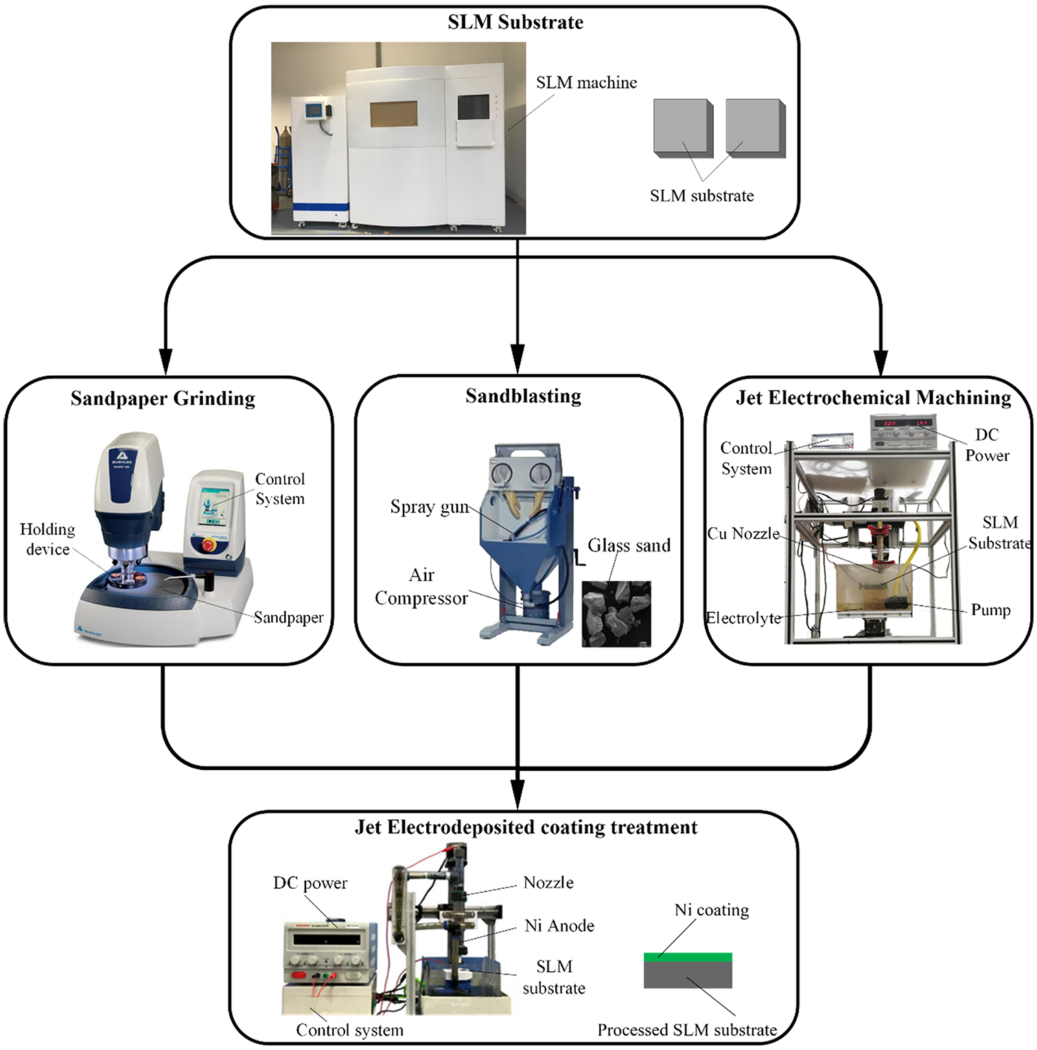
Schematic diagram of experimental process.
Sandpaper grinding
The sandpaper grinding process is carried out by contacting the substrate with sandpaper and reciprocating on the surface of sandpaper. This process can be thought of as many tiny “tools” cutting simultaneously, so that the contact pressure between the substrate and sandpaper determines the amount of the grinding on the surface of the substrate. In the experiment, 400# sandpaper was selected and placed on an automatic polishing machine. Samples with the same specifications were ground with different contact pressures of 10, 15, and 20 N, and each sample was processed for the same grinding time.
Sandblasting
In the sandblasting process, when a large amount of high-speed abrasive collides with the surface of the material, its velocity changes instantaneously and the surface of the material absorbs the kinetic energy of the abrasive. When the yield limit of the material is exceeded, the surface layer will undergo plastic deformation and form microscopic pits, leading to the changes in the shape and direction of the crystalline particles. 14
Figure 3 shows a schematic illustration of the working principle of the sandblasting used in this work. A sand blasting machine was used in the experiments. Glass sand was used as the abrasive and an air compressor was used to create negative pressure in the spray gun. To achieve the surface treatment effect, the glass sand was sucked into the gun under the action of the pressure, and then was sprayed onto the SLM substrate surface to be processed with the airflow through the nozzle. Therefore, the degree of plastic deformation of the SLM substrate is determined by the working pressure used in sand blasting. In this experiment, sandblasting pressures of 1, 2, and 3 bar were selected to conduct the sandblasting treatment on the SLM substrate samples with the same size, and using the same processing time.
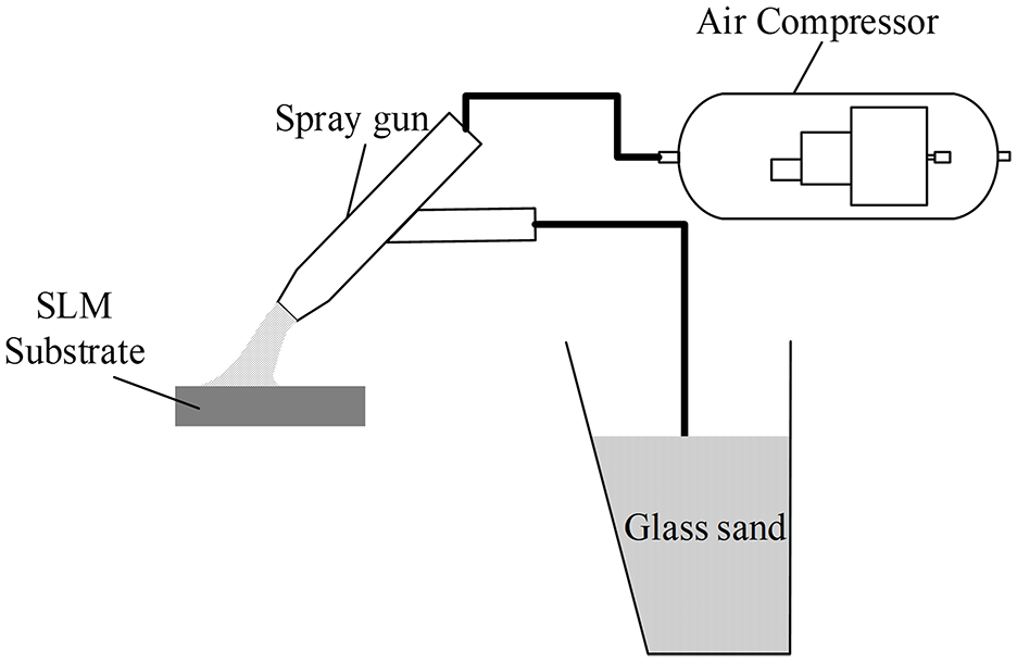
Schematic illustration of the sandblasting.
Jet electrochemical machining
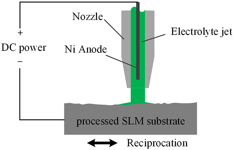
Jet electrochemical machining is an improved form of electrochemical machining in which the substrate is only machined in the area impacted by the electrolyte jet. Figure 4 shows a schematic diagram of the jet electrochemical machining process. During jet electrochemical machining, the SLM stainless steel acting as the anode will oxidize and dissolve to some extent. The high-speed electrolyte flows out of the nozzle and removes the anodic corrosion products and other impurities. This process flattens the adhesion particles and other defects on the surface of the SLM parts.15-17
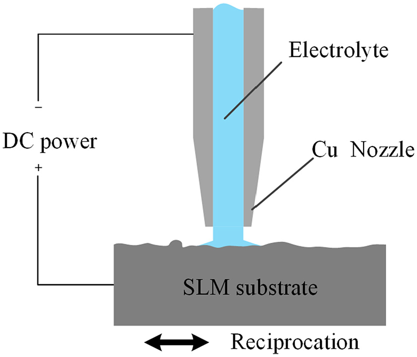
Schematic illustration of the jet electrochemical machining.
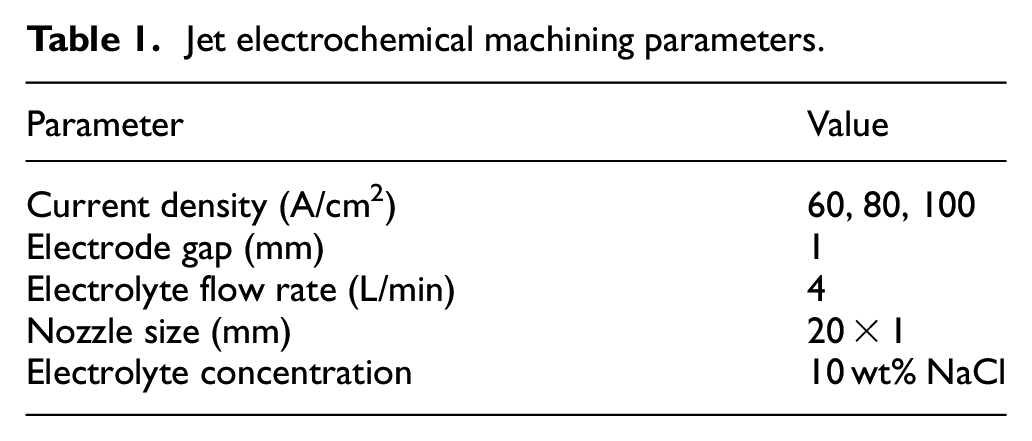
In this experiment, a self-developed jet electrochemical machine was used, and the jet electrochemical machining parameters are shown in Table 1. According to Faraday’s law, the metal mass dissolved at the anode is positively correlated with the current density. Therefore, the current density parameters of 60, 80, and 100 A/cm2 were selected as the variables in the experiment. SLM substrates are processed by jet electrochemical machining for the same time.
Jet electrochemical machining parameters.
Surface nickel coating by jet electrodeposition
After the SLM substrate was treated using the three above-described methods, a nickel coating was deposited on the surface of the substrate by jet electrodeposition. In jet electrodeposition, the metal ions in the electrolyte are reduced to neutral atoms at the cathode under applied voltage to form precipitates. A schematic diagram of this process is shown in Figure 5. Under the action of the positive electrode potential supplied by the DC power, the nickel atoms on the surface lose electrons and become nickel ions in the electrolyte. Then, under the action of the potential difference of the solution, the nickel ions gradually move toward the cathode SLM substrate. On the cathode surface, nickel ions capture electrons and undergo a reduction reaction, so that nickel atoms are deposited on the surface of the SLM substrate. 18
Schematic illustration of jet electrodeposition.
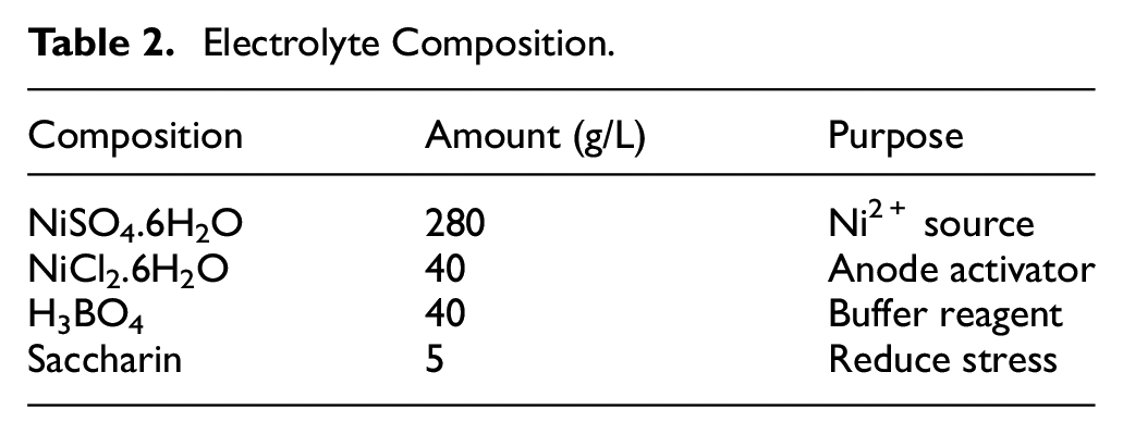
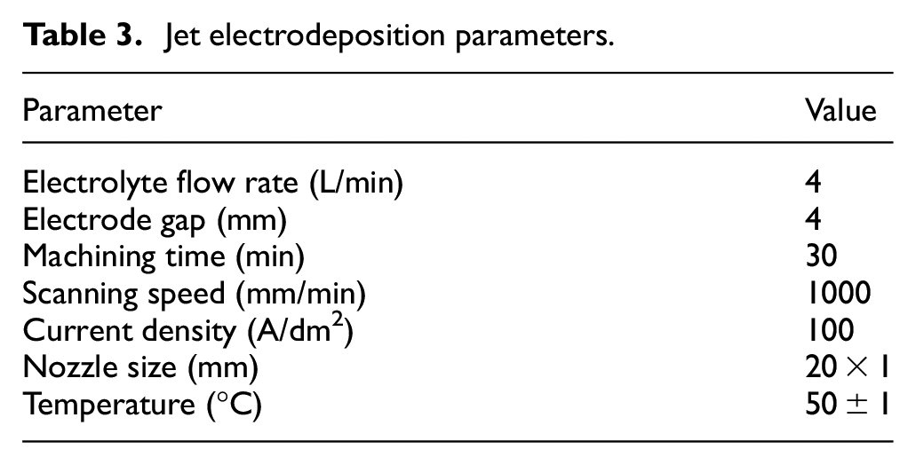
A self-developed jet electrodeposition machine was used in this experiment. The system includes a mechanical transmission system, control system and solution circulation system. The mechanical transmission system can control the machining position, scanning range and scanning speed. The control system can adjust the mode of the constant voltage or constant current power supply, the machining time, and control the parameters of the solution and the mechanical parts in an integrated way. The solution circulation system controls the injection velocity, nozzle shape, and solution temperature. The composition of the electrolyte selected in this experiment is shown in Table 2, and the parameters of the jet electrodeposition are shown in Table 3.
Electrolyte Composition.
Jet electrodeposition parameters.
Characterization of experimental results
An S-4800 cold field emission scanning electron microscope (Hitachi, Japan) was used to measure the surface microstructure of the processed substrate and the surface nickel coating. The corrosion resistance of the coating was tested at room temperature using a CHI660 three-electrode electrochemical workstation (Shanghai Huachen Co., Ltd., China). The sample was immersed in 3.5 wt% NaCl solution for approximately 30 min to obtain the open circuit potential (Eocp). The reference electrode was a saturated calomel electrode, and the reference electrode was a platinum electrode. The range of the dynamic potential scanning was ±500 mV, and the scanning rate was 1 mV/s. Coating adhesion was tested using a WS-2005 automatic coating adhesion scratcher (Lanzhou Zhongke Kaihua, China). The load was 40 N, the scratch length was 3 mm, the static load length was 2 mm, the reciprocating frequency was 1 Hz, and the static pressure time was 30 s. The scratch morphology of the coating was observed using an CX33 optical microscope (Olympus, Japan).
Results and discussion
Surface morphology
Figure 10(a) shows the original appearance of the untreated SLM substrate surface. It is observed from the figure that a large number of adhesive particles are present on the surface of the SLM substrate. This is due to the insufficient laser power used in the SLM processing and an excessively high speed of the laser motion so that the metal powder was not fully melted prior to solidification.19,20 In addition, since the SLM part is formed by stacking layer by layer, the lack of full melting can easily lead to high surface roughness of the surface and defects such as gullies. Figure 10(b) shows the surface morphology of the nickel coating on the SLM substrate without treatment. Due to the adhesive particles on the surface of the substrate, the nickel coating formed a large bulge, and the size of the crystal cells on the surface of the coating was not uniform, with gully stripes, and holes appeared on the surface of some areas. Figure 6 shows a diagram of the processing of the untreated SLM matrix and its surface coating.
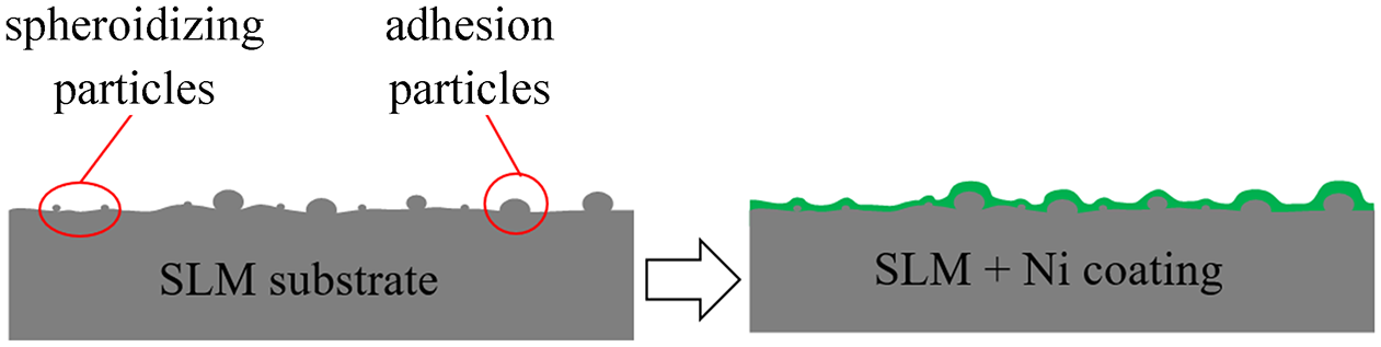
Schematic diagram of the untreated SLM substrate with Ni coating.
Figure 10(c) shows the surface of the substrate after grinding under a pressure of 20 N. As the grinding progresses, most of the defects are ground away, and only some tiny spheroidized particles are present while the entire surface is smooth. However, some large adhesive particles exist on the surface of the initial substrate, and these adhesive particles fall off from the surface under the action of external forces during grinding, forming pits on the surfaces of the parts. Figure 10(d) shows the surface morphology of the nickel coating after sandpaper grinding. Due to the large number of scratches on the surface of sandpaper after grinding, the nickel coating also presents the same striation morphology as the substrate during the formation process, and tiny crystal cells caused by spheroidized particles are present in the coating. However, in certain areas, the coating ruptures in the pit caused by adhesive particles fall off from the surface. Figure 7 shows a schematic diagram of the sandpaper grinding and surface coating processing.
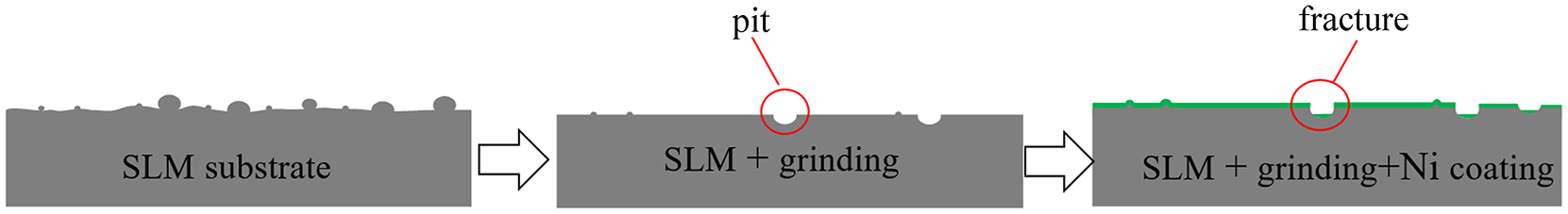
Schematic diagram of sandpaper grinding with Ni coating.
Figure 10(e) shows the substrate surface after sandblasting at a pressure of 3 bar. It is observed from the figure that some tiny spheroidized particles “disappear” due to plastic deformation. However, the plastic deformation of some large adhesive particles is limited and does not “disappear” completely even after the impact of sand particles. This will lead to the appearance of obvious undulation of the surface of the substrate. Figure 10(f) shows the morphology of the nickel coating on the surface of the substrate after the sand blasting treatment. Obvious height variation similar to those of the substrate are observed for the coating. This is due to the characteristic “tip discharge” effect of jet electrodeposition that will make the nickel ions tend to reduce to atoms at the peak where the discharge is easier, resulting in a thicker coating at the peak and thinner coating at the trough. 21 The uneven thickness of the coating is very harmful to the coating structure and adhesion when the internal stress is released, and leads to the easy generation of micro-cracks and can even lead to the rupture of the coating. Figure 8 shows a schematic illustration of the sand blasting and surface coating processing.
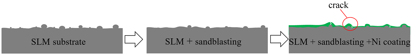
Schematic diagram of sandblasting with Ni coating.
Figure 10(g) shows the surface treated by jet electrochemical machining with a current density of 100 A/cm2. It is observed from the figure that the adhesive particles have been completely removed, and the surface is smooth without any undulations, obvious spheroidization particles, gullies, and other defects. The surface of the substrate shows a complex microporous structure formed by electrochemical dissolution.22-24 Figure 10(h) shows the surface of the nickel coating after the jet electrochemical machining treatment. Due to the above-discussed “tip discharge” effect, the electric field lines are denser at the tiny bulge and facilitate the formation of tiny cells. These tiny cells grow gradually and collide with each other, greatly improving the densification and flatness of the coating, while a good mechanical interlocking structure is formed between the coating and the substrate, improving the adhesion of the coating. Figure 9 shows a schematic diagram of the JECM and surface coating processing.
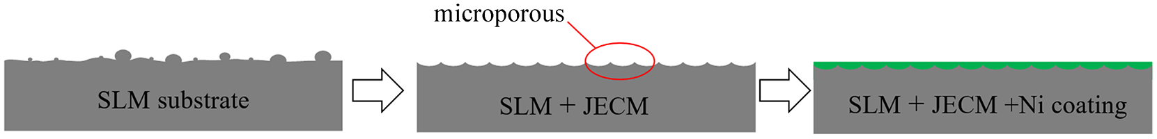
Schematic diagram of JECM with Ni coating.
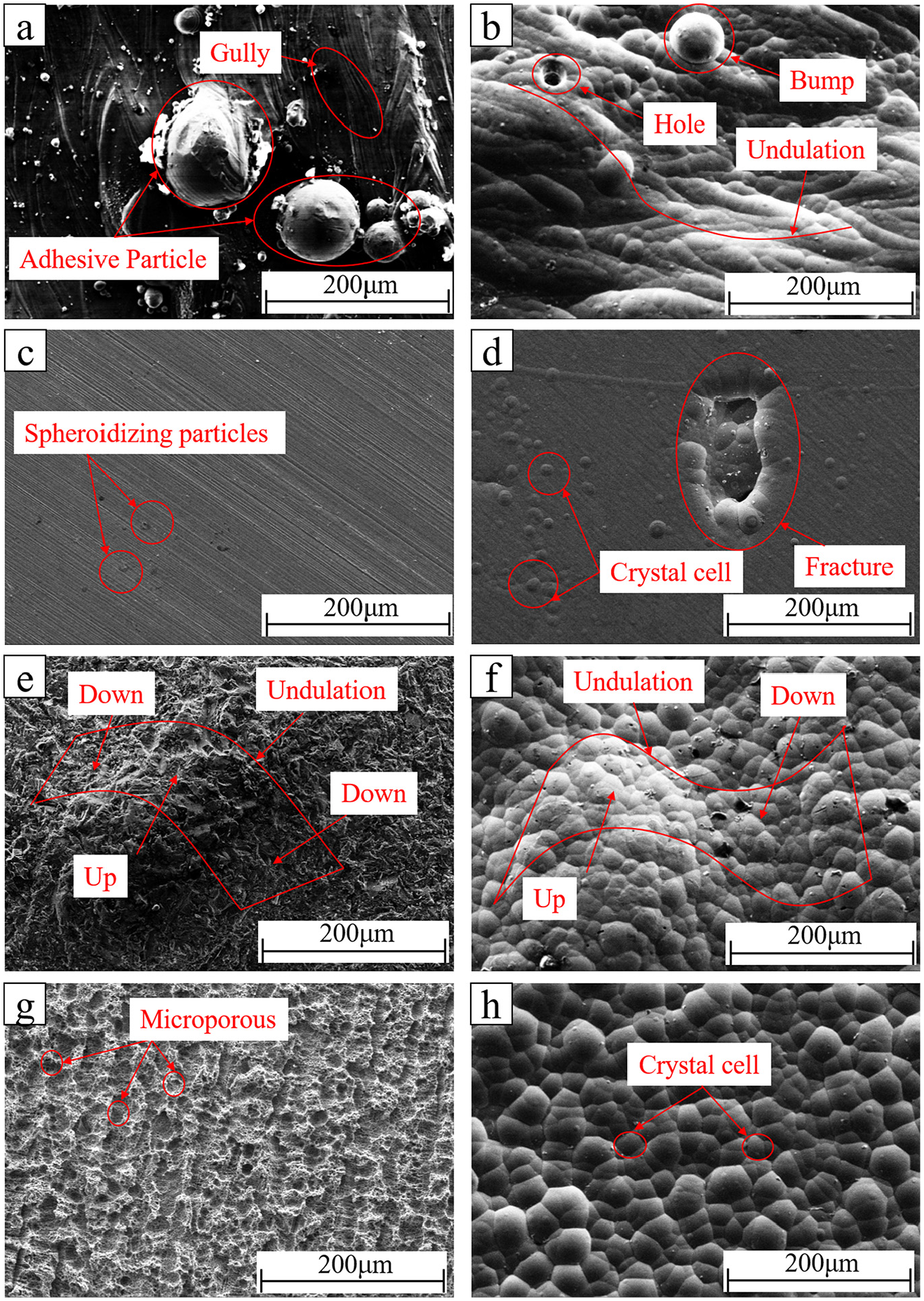
Morphology of the SLM substrates and nickel coatings treated by different methods (a) SLM substrate without treatment (b) Morphology of Ni coating deposited on untreated substrate (c) SLM substrate after sandpaper processing at 20 N (d) Morphology of Ni coating deposited on the substrate after sandpaper processing at 20 N (e) SLM substrate after sandblasting processing at 3 bar (f) Morphology of Ni coating deposited on the substrate after sandblasting processing at 3 bar (g) SLM substrate after electrochemical jet machining with 100 A/cm2 (h) Morphology of Ni coating deposited on the substrate after electrochemical jet machining with 100 A/cm2.
Compared with the reference 25 , due to the extremely high thermal effect of laser, the substrate surface is easy to oxidize after laser treatment. With the increase of laser power, the color of the sample surface gradually turns black. When the laser energy density reaches 3 J/cm2, the oxygen content on the substrate surface increases by 2.6%. However, the SLM substrate treated by jet electrochemical machining has no heat affected zone and the surface quality is better.
Corrosion resistance
Figure 11 shows the polarization curve of nickel coating in a 3.5 wt% NaCl solution after the SLM substrate was treated by different treatment methods. Table 4 shows the corrosion potential (Ecorr) and corrosion current density (Icorr) values obtained from the polarization curves. The corrosion potential (Ecorr) and corrosion current (Icorr) are the corresponding potentials and currents when the metal material reaches a stable corrosion state without applied current. Corrosion potential corresponds to the corrosion tendency under thermodynamic theory, reflecting the degree of difficulty of metal corrosion. The higher the corrosion potential of metal is, the smaller the corrosion tendency is, and the more difficult the corrosion is. The corrosion current corresponds to the corrosion rate, which reflects the speed of reaction rate when the metal is corroded. The smaller the corrosion current is, the slower the corrosion reaction rate is and the slower the corrosion diffusion is. 26
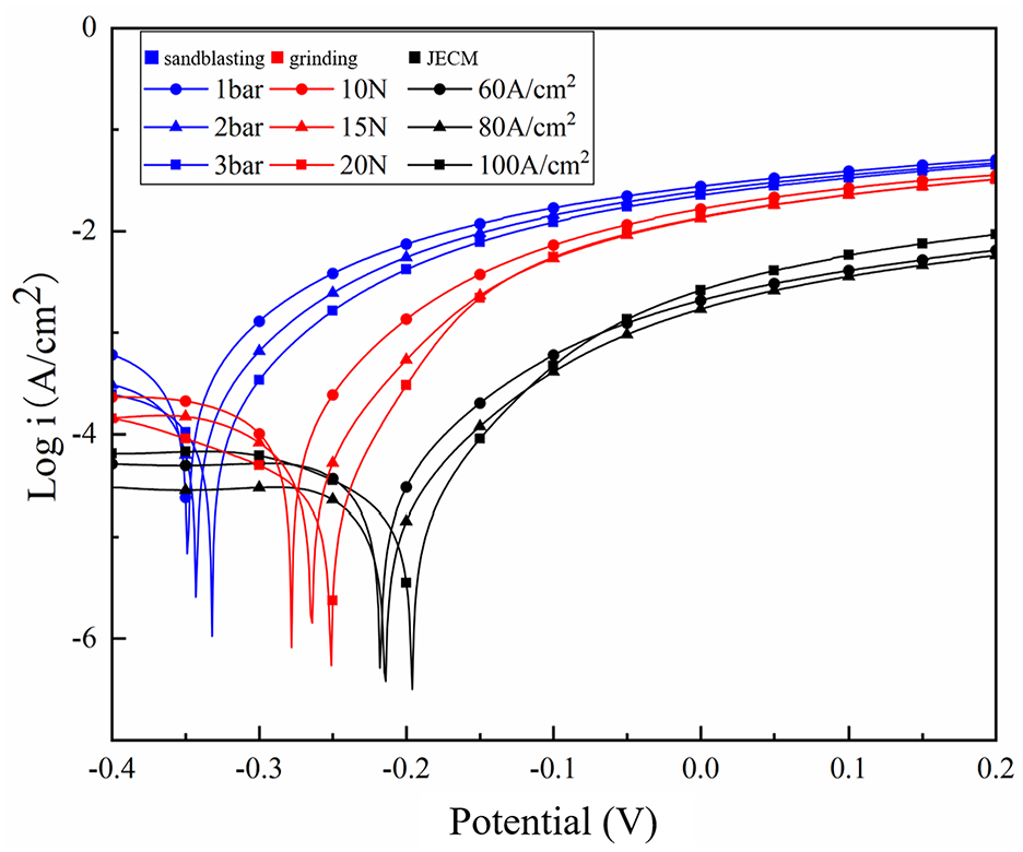
Polarization curves of nickel coatings on SLM surfaces after using different processing methods.
Corrosion potential and corrosion current density of nickel coating.
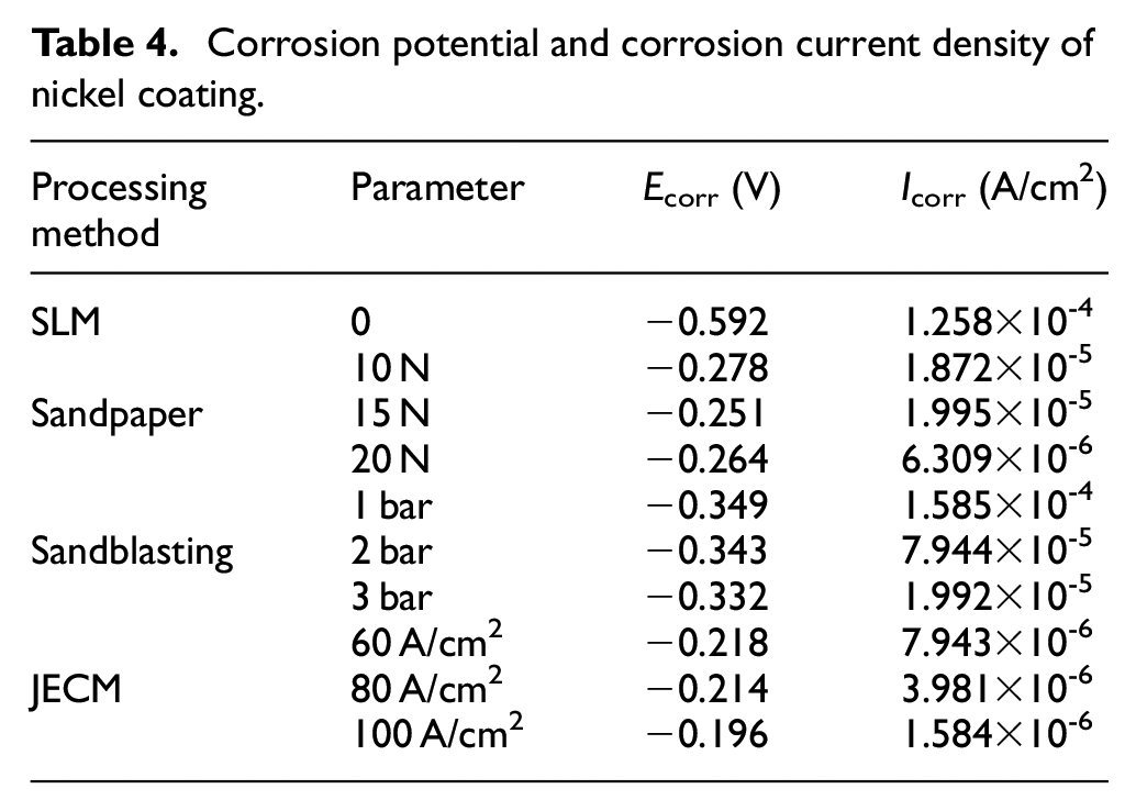
Corrosion of materials generally begins at the surface, particularly at the defects such as microcracks and pores. As shown in Table 4, the surface of the untreated SLM substrate contains more adhesive particles, pores and other defects. After jet electrodeposition treatment, many holes are present in the coating, and this coating shows the worst corrosion resistance due to the micro-cracks caused by the adhesion particles, the maximum corrosion potential of the coating is −0.592 V, and the minimum corrosion current density is 1.258 × 10⁻⁴ A/cm2.
The surface of the substrate treated with sandblasting is rough. Although some smaller spheroidized particles have “disappeared,” the larger adhesive particles in the sandblasting process are impacted by glass sand, but the plastic deformation is limited and does not “disappear” completely, leading to the undulations of the surface. Due to the “tip discharge” effect of jet electrodeposition, the coating is thicker in the relatively higher area and thinner in the relatively lower area. With the release of internal stress, microcracks occur in the coating. It is observed from Figure 11 that the corrosion resistance of the nickel coatings is greatly reduced compared to the other two methods. The maximum corrosion potential of the coating is −0.332 V, and the minimum corrosion current density is 1.992 × 10⁻⁵ A/cm2.
The surface roughness of the SLM substrate after sandpaper grinding is better, and its surface roughness is clearly improved. However, as discussed in section 3.1, in the process of sandpaper grinding, some adhesive particles fall off the surface of the substrate, leaving some pits on the surface. This will result in surface nickel coating rupture, and reduced corrosion resistance. The maximum corrosion potential of the coating is −0.251 V, and the minimum corrosion current density is 6.309 × 10⁻⁶ A/cm2.
However, when the surface is treated by electrochemical jet machining, the tool cathode has no contact with the surface of the substrate, and all spheroidized particles and adhesive particles on the surface of SLM parts are removed by chemical energy corrosion. After the electrochemical treatment, the surface uniformity is good and the coating surface is smooth and compact. The corrosion resistance of the coating is effectively improved. The maximum corrosion potential of the coating is −0.196 V, and the minimum corrosion current density is 1.584 × 10⁻⁶ A/cm2.
Based on the above analysis, it is concluded that when a nickel coating is deposited on the SLM substrate surface after sandblasting, the corrosion potential of the coating is the most negative and the corrosion current density is the highest. The corrosion resistance of nickel coating deposited on the substrate surface after sandpaper grinding is improved to some extent. The nickel coating displays the best corrosion resistance after the treatment of the surface of the substrate by electrochemical jet machining. Therefore, different surface treatments of SLM substrates have important effects on the corrosion resistance of nickel coatings.
Coating adhesion
A large number of theoretical models have proved the relationship between scratch and coating adhesion. Detection of adhesion is based on the application of a vertical load and probe to rub the coating surface in the horizontal direction. Upon the rupture of the coating in the vicinity of the probe, the friction coefficient suddenly either increases or decreases, thus determining the critical value of the adhesion between the coating and the substrate. 27 The test results of the scratch method of the coating for the SLM substrate surfaces treated by different methods are shown in Figure 12.
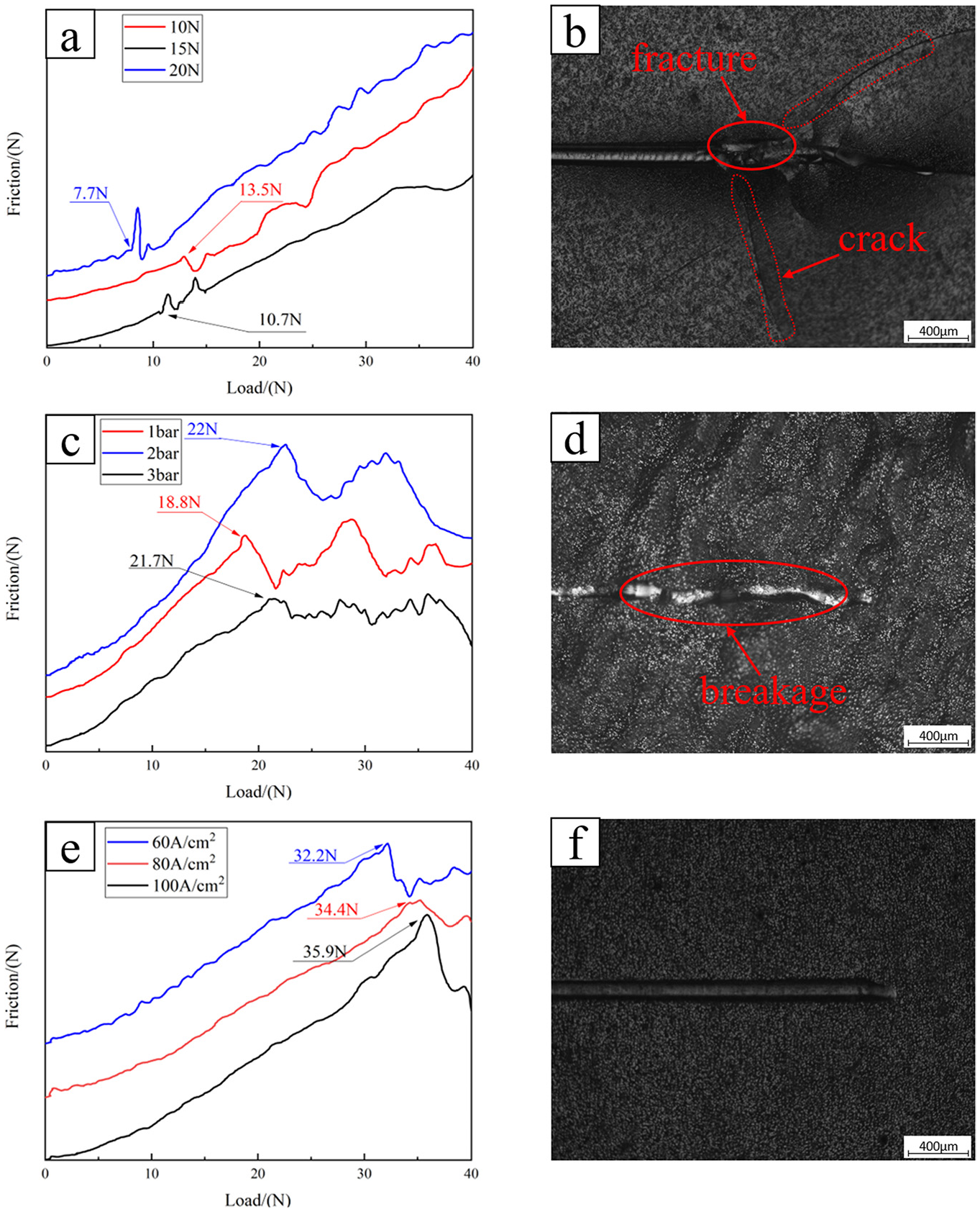
Adhesion curves and scratch morphology of nickel coating onto the SLM-formed substrate. (a) Adhesion curves for sandpaper processing with 10, 15, and 20 N (b) scratch morphology of nickel coating for sandpaper processing with 20 N. (c) Adhesion curves for sandblasting processing with 1, 2, and 3 bar (d) scratch morphology of nickel coating for sandblasting processing with 3 bar (e) Adhesion curves for jet electrochemical machining with 60, 80, and 100 A/cm2 (f) Scratch morphology of nickel coating for jet electrochemical machining with 100 A/cm2.
For the SLM base without any treatment, the corresponding coating scratch curve fluctuates greatly and the appropriate binding force value cannot be determined.
Figure 12(a) shows the adhesion curve of the nickel coating on the surface after sandpaper grinding. It is observed from the figure that with increasing grinding pressure, the adhesion force of the nickel coating decreases gradually. This is because with increasing grinding pressure, the corresponding grinding amount of the substrate increases, the surface of the substrate gradually becomes smooth, and the coating cannot be closely attached to the surface of the SLM parts leading to poor adhesion. Figure 12(b) shows the scratch morphology of the coating corresponding to the base treated with a grinding pressure of 10 N. It is observed that the coating soon bulges and then ruptures.
Figure 12(c) shows the adhesion curve of the nickel coating deposited on the SLM-formed part surface after sandblasting. It is observed from the figure that when sandblasting is used as a pre-treatment, the coating adhesion was enhanced with increasing sand blasting pressure. For the sandblasting working pressure of 1 bar, the glass sand hits the SLM surface at a low speed, and the adhesive particles on the surface form a small amount of plastic deformation and generate a high surface roughness. When the working pressure increases to 2 and 3 bar, the flatness of the substrate surface is significantly improved. However, due to the limited plastic deformation caused by some large adhesive particles, the surface still shows undulations. Comparison to Figure 12(a) shows that the binding force of the coating on the surface processed by the sandblasting treatment is improved to a certain extent compared with sandpaper grinding. Figure 12(d) shows the scratch morphology of the coating corresponding to the substrate after a sandblasting treatment at a pressure of 2 bar. It is observed that the nickel coating breaks in the middle part of the scratch due to the surface fluctuation.
Figure 12(e) shows the adhesion curve of the nickel coating on the surface obtained after jet electrochemical machining. The curve clearly shows the positive correlation between the current density and coating adhesion. With increasing current density, almost all of the spheroidized particles, gullies and other defects on SLM substrate were removed, and the surface showed a uniform and dense microporous structure. Comparison of Figures 12(a), (c) and (e) shows that the nickel coating displays the best adhesion force when electrochemical jet machining is used as the treatment for the SLM-formed part surface. Figure 12(f) shows the scratch morphology of the nickel coating corresponding to the substrate processed with a current density of 100 A/cm2. The scratch did not cause obvious damage to the coating, and the adhesion between the coating and the substrate was perfect.
To sum up, when the SLM substrate is treated by different treatment methods, the binding force of corresponding coating is very different. The maximum binding force of the SLM substrate corresponding to nickel coating after grinding with sandpaper is 13.5 N. In reference 20, Wang et al. prepared nickel coating on the surface of the substrate by jet electrodeposition after pretreatment with sandpaper. The adhesion of the coating was detected to be 17 N, 28 which was similar to the experimental results in this paper. The maximum binding force of nickel coating on SLM substrate after sandblasting treatment is 22 N. And, in other methods, such as laser processing, the maximum binding force of coating is 32.5 N. However, after using JECM treatment, the coating binding force reaches the maximum of 35 N, so JECM is a beneficial surface treatment, and further improvements in the effectiveness of this treatment may be obtained in future research on the optimization of processing parameters.
Conclusions
After jet electrochemical treatment, the surface of the SLM-formed stainless steel part has a uniform porous morphology and interlocking structure with the surface nickel coating. This demonstrates the advantages of the use of jet electrochemical machining in applications and this method is expected to be highly effective for the surface treatment of the SLM-formed complex structures.
The corrosion potentials of the coatings corresponding to untreated, sandblasting, grinding and JECM are −0.592, −0.332, −0.251, −0.196 V, respectively. Therefore, the corrosion resistance of the coating after the JECM treatment is improved by 66.8%, 40.9%, and 21.9%, respectively compared with other methods.
The jet electrochemical treatment effectively improves the adhesion between the coating and the substrate, with the maximum bonding force between the substrate and the nickel coating reaching 35 N. The improvements of the bonding force compared to the bonding force values obtained after sandpaper grinding and sandblasting treatment were 160% and 59%, respectively. Thus, the binding force is greatly improved.
The JECM-JED combined processing method can avoid the shortcomings of the traditional surface treatments of the SLM-formed parts. It is hoped that this combined processing method will be widely used in the field of metal additive manufacturing.
Footnotes
Declaration of conflicting interests
The author(s) declared no potential conflicts of interest with respect to the research, authorship, and/or publication of this article.
Funding
The author(s) disclosed receipt of the following financial support for the research, authorship, and/or publication of this article: This work was supported by the National Key Research and Development Program “Additive Manufacturing and Laser Manufacturing” (Nos. 2018YFB1105801, 2018YFB1105400), the National Natural Science Foundation of China (No. 51475238), the Key Research and Development Program of Jiangsu Provincial Department of Science and Technology of China (No. BE2019002) and the China Post Doctoral Fund (No. 2020M671475).