
Abstract
Fatigue performance is a major consideration for critical aerospace components. The influence of surface grinding and rough/finish wire electrical discharge machining (WEDM) on the high cycle fatigue performance of a binary Ti50.8-Ni49.2 shape memory alloy was assessed. The effect of machined workpiece surface integrity in terms of surface roughness and subsurface microhardness on the fatigue results was also evaluated, in addition to fractography analysis. Testing was performed using a tensile-tensile regime at an elevated temperature of 150°C with specimens in the austenitic phase. Ground samples showed the highest fatigue strength of 390 MPa at run-out of 1.2 × 10⁷ cycles, while finish and rough WEDM specimens were 21% and 57% lower respectively, despite the finish WEDM surfaces having significantly lower roughness. This was likely due to the presence of tensile residual stresses following WEDM. All of the S-N curves however exhibited a relatively flat response with no clear indication of endurance limits. This implies that the different machining processes/conditions affected the fatigue strength of the material, but not the overall trend/shape of the fatigue curves.
Keywords
Introduction
Shape memory alloys (SMAs) form a class or family of materials which are able to undergo a change in properties/shape due to a reversible crystallographic/microstructural phase transformation (either martensite to austenite or vice-versa), which can be induced by a temperature change or applied stress. Fundamental aspects of SMAs together with their development, manufacture, processing and characterisation are comprehensively outlined in a number of publications.1–3 Commercially significant SMAs relate to three alloy systems based on NiTi (nickel-titanium), Cu and Fe, with nickel and titanium intermetallic compounds the most important, not least because they show the largest shape memory effect (largest recoverable strain).4,5 In addition to metallic alloys, polymers can also be produced which exhibit the shape memory effect, as can composite structures. 5 Component applications broadly include automotive actuators/springs and couplings, a growing range of biomedical implants, stents, filters and dental orthopaedic items, while in the aerospace sector larger scale deployable structures and morphing wings are cited.2,5,6
As with more standard Ni-based superalloys and Ti-alloys of the type used in aeroengine applications which are classed as difficult to machine, the machinability of NiTi SMAs is similarly poor when using conventional shearing processes. This is due additionally to their high ductility and propensity to strain harden, producing elevated levels of tool wear, poor chip breaking together with workpiece adhesion and burrs.3,4,7–9 The use of non-traditional machining processes such as electrical discharge machining (EDM), laser beam and waterjet systems offer some benefits particularly with small/micro components,10,11 however the thermal nature of both EDM and laser operation, while subject to a degree of control depending on operating mode, have the potential to adversely affect workpiece integrity through the formation of recast layers and heat affected zones,12,13 which can consequently influence product performance and service life. Published research on the EDM of SMAs have largely focused on the wire-EDM (WEDM) configuration and have primarily involved investigating the effect of key operating parameters on resulting workpiece surface and subsurface characteristics together with material removal rate (MRR). 14 When evaluating the WEDM of a ternary TiNiCu (titanium-nickel-copper) based SMA, Narendranath et al. 15 reported that workpiece surface roughness generally increased with higher peak current (5 A) and pulse on time due to the greater discharge energy and spark intensity, although surface roughness was found to decrease with increasing pulse on time at lower peak current (3 A). Non-linear trends however were observed for MRR due to the interactions between the process parameter levels (peak current, pulse on time and pulse off time) employed, which led to variations in material melting and re-solidification rates in the spark gap as well as flushing efficiency. It was found that intermediate current levels together with lower pulse on time and higher pulse off time was preferred to maximise MRR as this led to better removal of the debris in the spark gap leading to more stable spark discharges. Soni et al. 16 investigated the effect of varying servo voltage, pulse on time, pulse off time, servo feed and wire feed rate when WEDM of a TiNiCo (titanium-nickel-cobalt) SMA. While both the servo and wire feed rate was found to have negligible influence, rising pulse on time led to higher MRR and workpiece surface roughness due to the increased spark intensity. In contrast, increasing pulse off time and servo voltage resulted in reduced MRR and surface roughness. This was because higher pulse off times reduced the spark frequency and increased the duration for flushing of the debris, while larger servo voltages produced wider spark gaps that decreased the spark intensity and improved flushing. Analysis of the recast layer (re-solidified molten material) revealed that the thickness increased from 5 µm up to ∼44 µm with higher pulse on time and lower servo voltage, due to the greater transfer of thermal energy and melting of the workpiece material. A X-ray diffraction (XRD) evaluation of the recast layer showed the presence of hard oxides such as TiO2, NiTiO3 and NiO, which was responsible for the elevated microhardness (50% higher on average compared to bulk material) observed up to ∼45 µm beneath the machined surface. Similar trends and effects of the operating parameters were reported by other researchers when WEDM of binary NiTi SMAs.17,18 The influence of WEDM operation on the shape memory or recovery performance of two different ternary Ti-Ni-X SMA materials were assessed by Hsieh et al. 19 Despite the presence of ∼50 µm thick hardened recast layers on the workpiece surface following WEDM, there was no major detriment on the shape recovery property of both SMAs at normal bending strains (5%), with only a marginal reduction in shape recovery ability at increased bending strains (8%) due to the recast layer constraining the matrix of the TiNiX alloys.
For safety critical applications such as in the aeroengine industry, the standards and tolerances for workpiece surface integrity and particularly fatigue performance, is crucial. Hornbogen and Eggeler 20 define two forms of fatigue in SMAs. These are functional fatigue involving the loss or decrease in shape memory effect as a result of factors causing degradation in reverse phase transformation, and classical or structural fatigue comparable with conventional materials subject to high cyclic loads/stress. Here microstructural features and the effects of component machining can compromise life through the nucleation and propagation of cracks. 21 Aspects such as heat treatments and grain size on functional fatigue and the improvement achieved by grain refinement are well-understood, 1 as is the influence of environmental factors and operational effects. 22 Less comprehensive are published data relating to SMA structural fatigue due to machining and particularly thermal processes such as EDM, which until relatively recently was regarded with caution in relation to aerospace parts subject to high operating stress. When WEDM bar and sheet Nitinol (Ni50.8–Ti49.2) SMA using rough (main cut) and finish (trim cut) modes, Liu et al. 23 reported that discontinuous non-uniform porous and cracked (induced by tensile residual stress) recast layers between 2 and 8 µm thick were observed in the former (rough cut mode), while much thinner (0–4 µm) predominantly crack free layers were produced by the trim cuts. Significantly however, cracks did not propagate into the heat affected zone below the recast. In subsequent work with the same alloy, Liu et al. 24 presented ‘snapshot’ average fatigue life results for workpiece samples following main cut and trim cut WEDM operation using a room temperature tensile-tensile fatigue test regime, with the main cut samples failing at ∼48,000 cycles and the trim cut samples at ∼71,000 cycles. Adverse workpiece integrity measured with respect to surface roughness, near surface nano-hardness and recast layer characteristics was cited as key, with fractography showing fatigue cracks initiating from micro-voids in the thick recast layer.
The present work aimed to establish the influence of surface conditions generated by rough (single pass cut) and finish (multi pass cuts) WEDM on the high cycle fatigue (HCF) performance of a NiTi shape memory alloy. The fatigue performance was also assessed against samples machined by reciprocating surface grinding (RSG), which was identified as an alternative process for generating low damage/high integrity surfaces in SMA. The research and results detailed in this paper provides a valuable insight into the relative feasibility of WEDM and RSG processes for finish machining NiTi SMAs in terms of resulting workpiece surface integrity and fatigue performance (key measures in safety critical applications), which have not been previously outlined.
Materials and methods
The workpiece material evaluated was a binary titanium-nickel (Ti50.8-Ni49.2) SMA produced by rolling followed by heat treatment at 400°C for 1 h. The material was supplied in the form of rectangular plates measuring approximately 800 × 65 mm (L × W) with thicknesses of 3 and 12 mm respectively. The fatigue trials were carried out in tensile-tensile mode using a 20 kN rated Amsler Vibrophore electromagnetic resonance test machine equipped with an electric furnace having thermostatic control, which was mounted on an adjustable bracket to allow specimens to be centred within the heating chamber, see Figure 1(a). A K-type thermocouple probe was also attached to monitor specimen temperature during the tests, with Figure 1(b) showing the typical setup inside the furnace.
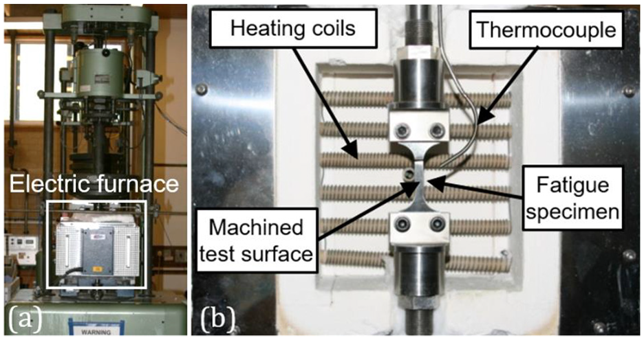
(a) Amsler Vibrophore machine and (b) fatigue test setup.
All tests were conducted at an elevated temperature of 150°C to ensure the material was in its austenitic phase as this was representative of service conditions for the envisaged application. The applied stress levels ranged between 170 and 460 MPa with a corresponding load ratio (R) of 0.1 and frequency of 80 Hz. The load ratio is the ratio of the minimum peak stress to the maximum peak stress for each loading cycle. Based on recommendations from Rolls-Royce, an S-N curve for each machining process was generated by testing at four different load levels where each run was repeated twice. Test run-out was set at 1.2 × 10⁷ cycles. As no fatigue performance data (S-N curves) under high cycle conditions for this particular alloy in the austenitic phase was known to exist, the applied load corresponding to the run-out stress for each process was first determined through preliminary trial runs commencing at ∼67% of the material’s yield strength (∼235 MPa at 140°C) and increased accordingly. Once run-out loads were established, the three remaining test levels were set by increasing the load in 20–30 MPa increments. Initial trials utilising conventional ‘bow tie’ shaped specimens however were unsuccessful, as failure repeatedly occurred at the clamped section of the sample instead of the gauge length. A finite element analysis revealed that this was due to the relatively low stiffness of the TiNi alloy (∼75 GPa against ∼205 GPa for Inconel 718) and clamping arrangement, which led to significant sample deflection at the specimen-grip interface during loading. This necessitated the development of a modified specimen design incorporating a ∼20% larger clamping area (maximum width increased from 19.05 to 30 mm) to reduce stress concentrations, held together using twin fasteners. The overall length of the modified test specimen was 80 mm together with a thickness of 2.25 mm, while the corresponding gauge length and width were 20 and 6.35 mm respectively. The machined test surfaces were the faces of the fatigue samples; see Figure 1(b).
The RSG fatigue test specimens were produced using the 3 mm thick material, which were initially cut into 100 mm long workpieces. Test surfaces were ground using a 180 mm diameter vitrified bonded SiC wheel (average grit size of 180 µm) on a Jones and Shipman 540AP surface grinder with the workpieces held on a vacuum chuck mounted on the magnetic worktable. The machine was also equipped with an Optidress attachment for periodic in situ dressing of the wheel as required. Equal amounts were ground from both sides of the plates to the final thickness of 2.25 mm. The operating parameters employed were cutting speed 30 m/s, table speed 0.15 m/s and down feed per stroke of 3 µm, which were established from results of prior RSG experiments also involving variation in grit size, with the 180 µm providing a balance between wheel life, grinding forces, productivity and workpiece quality. Grinding was performed with Trim C270 water miscible synthetic coolant (7%–10% concentration) delivered via two external nozzles at a flowrate of 3.5 l/min.
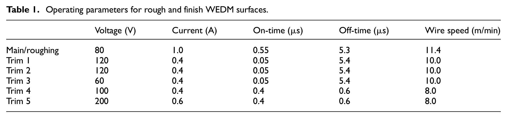
In contrast, the 12 mm thick workpieces (initially cut into 100 × 30 mm pieces) were utilised for fabricating the WEDM fatigue specimens as the thinner plates had insufficient material for accurate machining of both test surfaces. The rough and finish WEDM test surfaces were generated when cutting out fatigue specimen blanks measuring 83 × 30 × 2.25 mm (L × W × T) using 0.25 mm diameter uncoated brass wire on a Charmilles FI240CC machine installed with ‘CleanCut’ generator technology. Preliminary WEDM work was also carried out on an Agie Vertex showing comparable performance. The key FI240CC parameter levels are shown in Table 1, which were adapted and modified based on database technology developed for Ti-alloys in previous research.25,26 The rough WEDM surfaces involved only a single main/roughing cut while the finish WEDM surfaces comprised a roughing cut followed by a sequence of five finishing/trim passes. The fatigue specimen profile was then cut from the machined blanks using WEDM employing a five cut strategy (one roughing + four finishing passes). Finally, edges of the specimen profile were all hand polished using a range of SiC paper (P400, P600, P800, P1200 grades) to remove any residual damage from the WEDM operation and achieve the required corner radii, measured using a 0.43 mm radius gauge. The fractured surfaces of failed specimens were analysed using optical and scanning electron microscopes (SEM). Additionally, indicative workpiece surface roughness and microhardness data obtained from previous machinability testing (at similar parameters and conditions) involving the three machining processes, are outlined to support assessment of the fatigue results. The 2D surface roughness measurements were carried out using a Taylor Hobson Talysurf 120L at a cut-off length of 0.8 mm and corresponding evaluation length of 5 mm in accordance with ISO 4288. Microhardness depth profile evaluation was undertaken using a Mitutoyo HM-124 hardness tester equipped with a Knoop diamond indenter at a load of 25 g over a duration of 15 s for each indentation.
Operating parameters for rough and finish WEDM surfaces.
Results and discussion
Figure 2 details S-N curves showing the influence of surface grinding together with rough and finish WEDM on the HCF performance (>104 cycles) of Ti50.8-Ni49.2 SMA in the austenitic phase. Understandably, the fatigue strengths exhibited by the rough WEDM specimens were considerably inferior compared to their finish WEDM counterparts and up to ∼45% lower at run-out (∼170 against ∼310 MPa). This was attributed to poorer surface integrity in the former and a ∼10-fold higher workpiece surface roughness as detailed in Figure 3(a). The heavily cratered surface is indicated by the surface topography plot in Figure 3(b) and visualised in the SEM micrograph in Figure 3(c), which was attributed to the relatively higher discharge energies during the main/roughing cut. Understandably, in addition to the fall in roughness given by the significant change in operating parameter levels for the trim cuts (resulting in lower discharge energies), the texture produced by finish WEDM was also considerably more uniform, see Figure 3(d). Tensile residual stresses of up to 470 MPa extending to 150 µm beneath the machined surface was reported by Takale and Chougule 27 following single pass WEDM of a binary Ti49.4Ni50.6 SMA. The presence of tensile residual stresses typically reduces fatigue strength as it can exacerbate crack growth and propagation in the material.
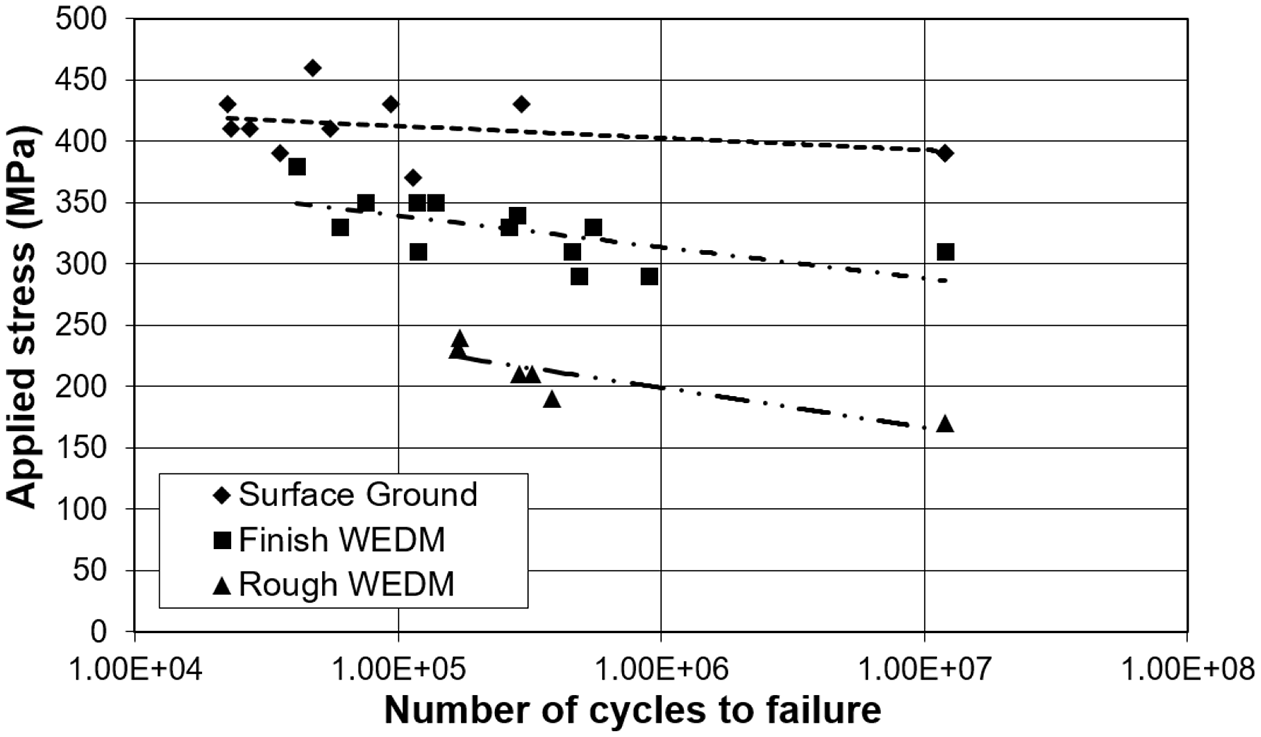
High cycle fatigue S-N curves of the three processes investigated.
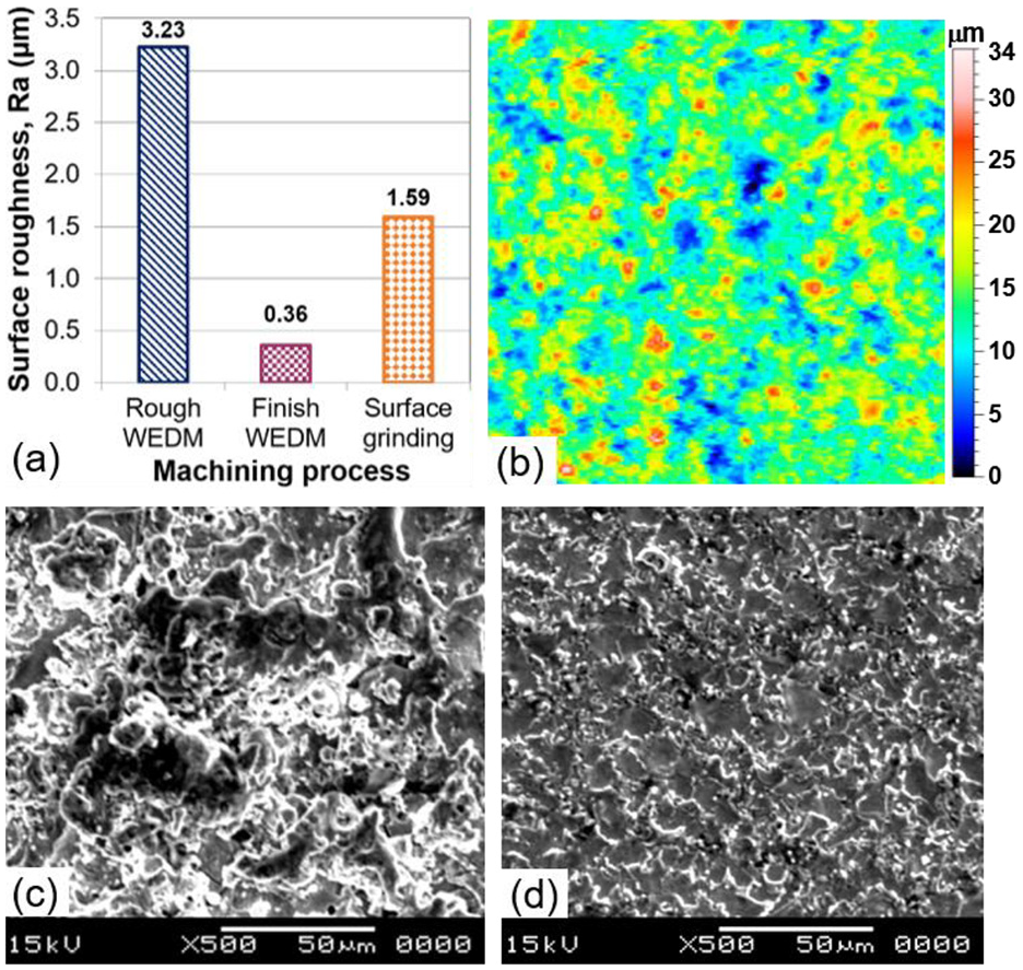
(a) Representative surface roughness levels of the three processes (b) 3D topography plot after rough WEDM and SEM micrographs of (c) rough and (d) finish WEDM TiNi surfaces.
The cross-sectional etched micrograph of a rough WEDM surface in Figure 4(a) details a semi-continuous recast layer up to ∼15 µm thick containing cracks, in contrast to the WEDM finish specimen in Figure 4(b), where there was little or no discernible trace of re-solidified material. There were no signs of cracking in the bulk material for WEDM operations, although microstructural flaws/artefacts are evident in Figure 4(a) and (b), possibly because of over-etching. Due to the thermal nature of the WEDM process, it is expected that a tensile residual stress regime will be induced in the surface/subsurface of the workpieces.
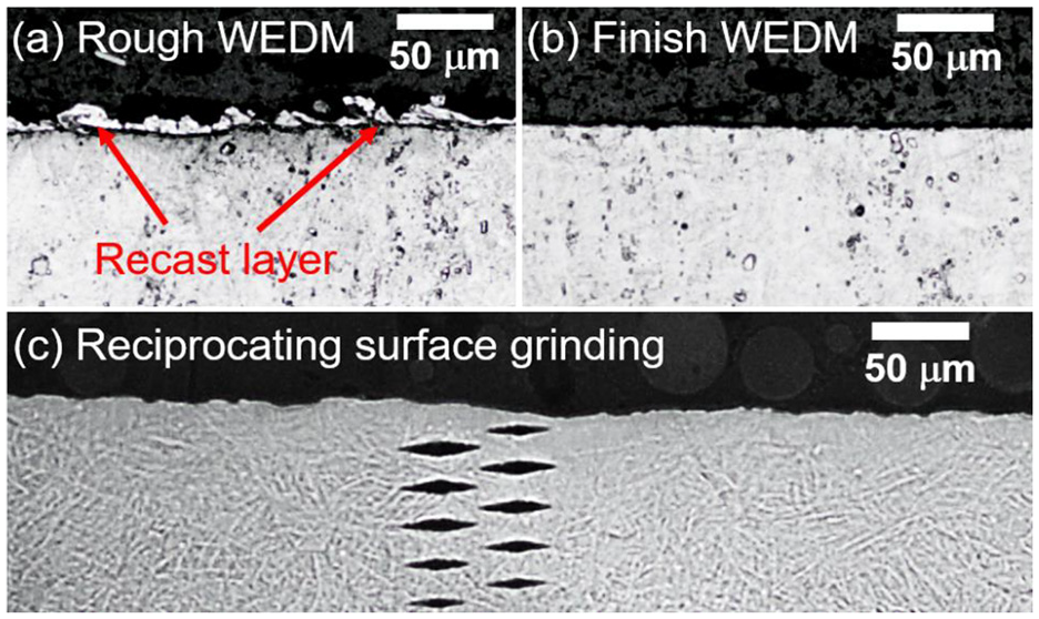
Representative cross-sectioned micrographs of TiNi workpieces following: (a) rough WEDM, (b) finish WEDM and (c) RSG.
Evaluation of microhardness depth profiles in Figure 5 showed workpiece softening down to ∼200 HK0.025 following both rough and finish WEDM. In the latter case, microhardness recovered to the bulk value (∼340 HK0.025) after ∼40 µm whereas the softened region on rough machined samples extended to a depth of ∼80 µm. This suggested the presence of a heat-affected zone (HAZ) even after finish WEDM. Although not directly measured in the present work due to time restrictions and equipment availability, it is reasonable to expect significantly greater tensile residual stresses in the rough WEDM samples compared to the finish surfaces, not least based on the evidence of the cracked recast and previous work on nickel and titanium alloys.26,28,29
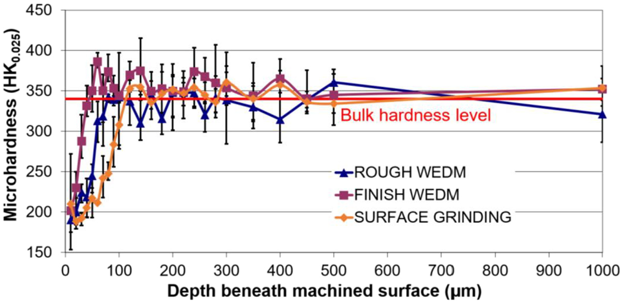
Representative microhardness depth profiles of TiNi workpieces following surface grinding, rough and finish WEDM.
The fatigue life of the RSG specimens with a run-out strength of 390 MPa outperformed the finish and rough WEDM samples by 26% and 129% respectively, see Figure 2. This was despite the average transverse roughness of RSG samples (1.59 µm Ra) falling between that of the WEDM surfaces. The measured normal grinding force during RSG of the SMA was approximately 100 N, causing plastic deformation and straining of the machined surface. This possibly induced compressive residual stresses in the surface, which can inhibit and delay crack initiation/propagation in the material and is a possible reason for the superior fatigue strength shown by the RSG specimens. The un-etched cross-sectional micrograph in Figure 4(c) shows the uneven topography of a RSG workpiece, which was due to the relatively coarse size (∼180 µm) of the grinding wheel grits and their propensity to regularly fracture during operation. Additionally, a partially visible intermittent recast layer measuring up to ∼3 µm thick is apparent, together with microhardness indentations extending into the bulk material. The measurements showed that RSG surfaces also exhibited a softened layer similar to that produced after WEDM but extended deeper up to ∼110 µm beneath the machined surface; see Figure 5. This would suggest some degree of thermal damage however, the samples showed no obvious discolouration or burn marks.
All of the TiNi S-N curves displayed a near flat and linear response with no obvious endurance limits even after 1.2 × 10⁷ cycles. This differs from the conventional ‘exponential decaying’ shaped curves typically observed when investigating the fatigue characteristics of WEDM and milled Udimet 720 and Ti-6246 alloys. 30 The trends seen here are more akin to the fatigue behaviour of γ-TiAl intermetallics subject to various machining processes including RSG, which also show relatively flat response curves. 31 Early work by Miyazaki and Otsuka 1 to evaluate the influence of workpiece heat treatment on the fatigue performance (tension-unloading mode) of TiNi SMA also showed similarly near flat S-N curves when operating in the high cycle region, although here machining effects were not considered and the testing performed at room temperature.
Figure 6 details sample optical and SEM micrographs of fractured fatigue specimen surfaces that failed in the region of 105 cycles for each of the three processes investigated. All of the cracks initiated from the machined test surfaces of the samples. The optical micrograph of the RSG specimen indicates a greater area of necking compared to the WEDM samples due to the higher level of loads applied as a proportion of yield stress. Following initiation, stable growth and propagation of the crack was observed due to successive cyclic loads as highlighted by the fatigue striations in the SEM micrographs.
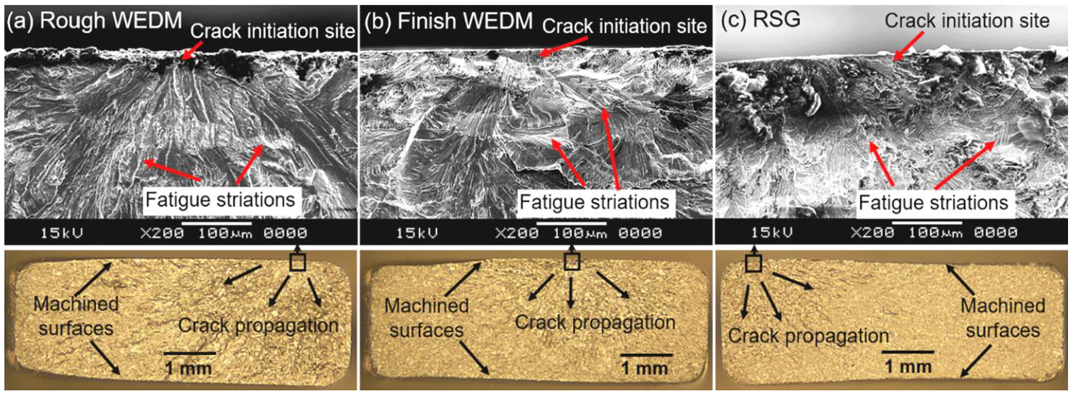
Sample micrographs of fractured surfaces for: (a) rough WEDM, (b) finish WEDM and (c) RSG fatigue specimens failing around 105 cycles.
Fatigue cracks generally (although not always) propagate from workpiece surface features, which can be mitigated by post processing such as shot peening or etching. The topography of the surface is therefore critical, including the shape and distribution of machining features together with the maximum height of the profile, although their effects are likely to be less significant in the presence of workpiece surface integrity effects, notably cracks or a tensile or compressive stress condition. In contrast to the directional surface of RSG characterised by sharp parallel valleys with a defined lay, WEDM surfaces are in general isotropic comprising a random arrangement of overlapping craters and discharge debris. With RSG, selection of operating levels is possible to minimise thermal degradation and effect sufficient straining of the workpiece near surface to impose a beneficial residual compressive stress regime, although this may suffer relaxation subject to subsequent thermal exposure. 32 For WEDM where discharge temperatures are high and there is no physical contact between the wire and workpiece, then for finish/trim pass samples with zero/minimal recast and HAZ, the best stress scenario is neutral or more typically it is low order tensile.
Conclusions
The application of multiple trim/finish passes to remove damage caused by the main/rough cut significantly improved the fatigue strength of WEDM surfaces by up to ∼82% at test run-out. In addition to the absence of any visible recast layer, workpiece surface roughness was also significantly reduced following finish WEDM due to lower discharge energies employed during the trim cuts. The RSG specimens exhibited even better fatigue performance with a run-out strength of 390 MPa (compared to ∼310 MPa for finish WEDM samples), which was ∼166% of the TiNi yield stress in the austenitic phase at 150°C. This was possibly due to mechanical straining/deformation of the workpiece material in RSG, leading to induced compressive residual stress that restricts crack initiation and growth/propagation. It is likely that optimisation to reduce ground surface roughness through use of a finer grit wheel would further improve fatigue life. The high cycle fatigue response (>104 cycles) of the SMA material showed a linear trend with shallow gradients regardless of machining operation, which would suggest identifying a safe stress level in component lifing extremely challenging.
Footnotes
Acknowledgements
The authors wish to thank Rolls-Royce plc, GF Machining Solutions, Iscar and the University of Birmingham. The assistance of Drs. John F. Webster, Wayne Voice, Neil Glover and Tim Doel are also gratefully acknowledged.
Declaration of conflicting interests
The author(s) declared no potential conflicts of interest with respect to the research, authorship, and/or publication of this article.
Funding
The author(s) received no financial support for the research, authorship, and/or publication of this article.