
Abstract
Self-excited vibrations of the face milling process can result in instability, poor surface finish and machine tool failure. In order to avoid chatter vibrations, this article develops an algorithm for predicting the stability lobes for face milling processes. It considers the factors including radial instantaneous chip thickness, entry and exit angles and the dynamic interaction between cutting tool and workpiece which is often neglected by many researchers. An electronic impact hammer is used to identify the dynamic parameters of the face milling system. Milling experiments have been conducted to validate the predictive capability of the developed algorithm for stability lobes. The results show that the prediction model can estimate the stable and unstable zones for face milling process. This article provides a frequency-domain method for establishing stability lobes which can predict stability zones rapidly. The outcome of this research will bring about methodologies for cost-effective monitoring of face milling processes and maximize the material removal rate.
Introduction
Nowadays, chatter is one of the most important restrictions for milling process.1,2 Due to chatter vibrations related to the dynamic flexibility of the machine tool structure, the productivity and material removal rate in milling process are limited. Hence, research on the stability of the face milling system is important. Stability analysis for face milling operations is much more complicated than other cutting process due to the rotation of the cutting tool and the interrupted nature of the cutting process.3,4 Besides, the directional coefficients (cutting force and the transfer function of chip thickness) vary with the cutting inserts rotating, which makes it more difficult to analyze the stability for face milling operations.5,6
During the last few decades, the analytical approaches to the prediction of stability have obtained great improvement for the high-speed milling process. Budak and Altintas 7 developed an analytical method to predict the chatter stability for end milling process by modeling the cutter and the workpiece as a multi-degree-of-freedom structure which led to a semi-analytical determination of stability limits. The dynamic interaction between the milling cutter and workpiece is modeled considering the varying dynamics in the axial direction. The model is further extended by Jensen and Shin8,9 to three-dimensional case which considers the effects of insert and cutter geometry, cutting conditions, process nonlinearity, entry and exit angles and the fully dimensional structural dynamics of both the machine tool and the workpiece. Iglesias et al. 10 propose a standard stability model focusing on heavy-duty operations with the effects of the whole workspace and feed directions in consideration. The proposed stability model can be used as a different way to obtain the stability charts and to select the most suitable tool considering the machinability reasons. Ahmadi and Ismail 11 developed the stability lobes analytically by taking into account the effect of nonlinear process damping. The developed lobes could be established under different amplitudes of vibration.
Guo et al. presented a new third-order discretization method to compute the stability lobes considering multi-regenerative chatter effect. A mathematical model, which was suitable for the dynamic system with non-uniform pitch cutter or cutter run-out, was established for multi-regenerative chatter. But the established stability lobes can only be used for end milling process for determining good cutting parameters’ combination. 12 Ozsahin et al. established stability lobe diagrams to avoid chatter vibrations by determining tool point frequency response function (FRF). In their research, chatter frequencies and the corresponding stable axial depths of cut are used for the tool point FRF identification; the variations in the tool point FRF under cutting conditions are determined for different holder–tool combinations. But damping is assumed to be proportional by taking the modal constant as a real number. 13
This work presents an algorithm for predicting the “stability lobes” for face milling processes by considering the effects of radial instantaneous chip thickness, entry and exit angles and the dynamic interaction between cutting tool and workpiece. By solving the characteristic equation for dynamic face milling system, the relationship between axial cutting depth and spindle speed is used to represent the stable area for the face milling system. The frequency-domain method for establishing stability lobes can predict stability regions rapidly. The solution process can be represented as shown in Figure 1.
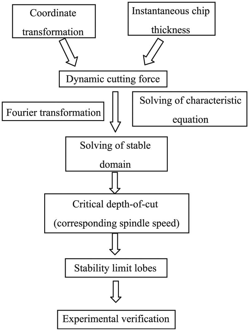
Solving process for stability lobes.
Formulation of stability lobes for face milling processes
The use of the term stability lobes has now become more significant with the introduction of the high-speed and variable speed machining. The calculation of the stability lobes is based on the FRFs of the systems’ structural dynamics. Until recently, the practical use of stability lobes as a means to predict chatter-free depths of cut has been mostly limited to turning operations. The reason is that milling operations are complicated by the rotation of the cutting tool, which introduces time-varying periodic cutting forces, chip loads and multiple-degree-of-freedom structural dynamics.
This section discusses the analytical modeling and formulation of stability lobes as they relate to face milling operations. The modeling method presented in this article is comprehensive and applicable to systems with multiple degrees of freedom. It is based on the fundamental physics of the cutting process and the regenerative mechanism.
The stability analysis of the dynamic milling system will lead to analytical relations between the chatter frequency, largely determined by spindle speed, and the chatter limit which is expressed in terms of depth of cut. Based on this information, “stability lobes” can be generated.
Face milling cutting forces at different coordinate systems
Three different coordinate systems are used for model description. CS0 is the global coordinate system of the cutting tool system. It is fixed and coincident with the main axes of the cutting tool system. As shown in Figure 2, Z-axis is set to be the direction of the spindle axis of the machine tool. The direction opposite to the feed direction of the workpiece is set to be X. Y is set in a direction perpendicular to X- and Z-axes, pointing to the side where the cutter exits the workpiece during an up-milling operation. The cutting force of the jth tooth can be divided into the orthogonal Fx(j), Fy(j) and Fz(j) components. CS1 is the local coordinate system located at the cutting point of each insert. It is oriented according to the radial, tangential and axial directions, and it rotates in conjunction with the tool. The cutting force of the jth tooth can be divided into tangential cutting force Ft(j), radial cutting force Fr(j) and axial cutting force Fa(j). CS2 is the cylindrical coordinate system coincident with the tool position in the machine workspace. The cutting force can be split into friction component Ff(j) and normal cutting force component Fn(j). θj is the angular rotation of the jth tooth rotating from the entry point to X measured in the X–Y plane. These coordinate systems are depicted in Figure 2.
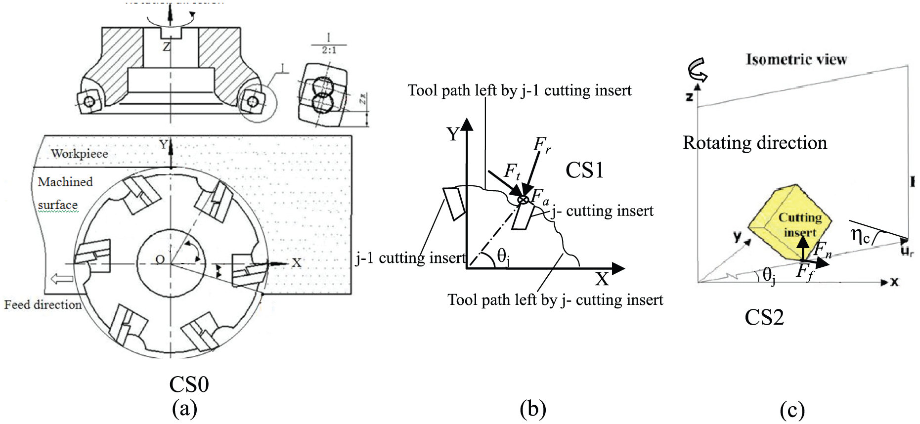
Three different coordinate systems are used for model description: (a) CS0, (b) CS1 and (c) CS2.
In CS2 system, at the rake face of the jth cutting tooth, γr is the radial rake angle and γq is the axial rake angle. The angle between friction and radial cutting force is called cutting layer angle ηc as shown in Figure 2.
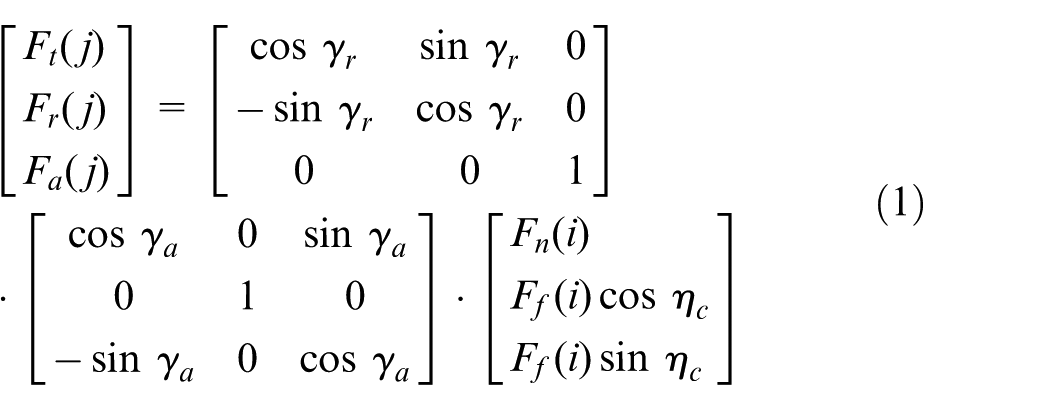
The transformation matrix from CS2 to CS1 can be expressed as
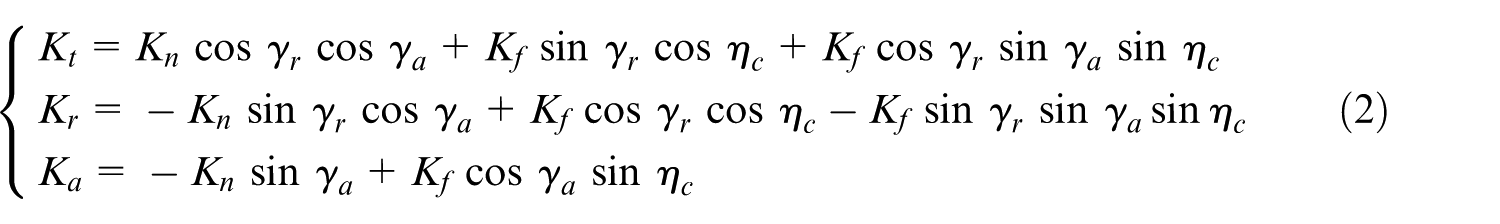
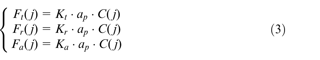
The cutting force coefficient in the normal direction and friction direction is Kn and Kf, respectively. Kt, Kr and Ka are the tangential, radial and axial cutting force coefficients, respectively. Kt, Kr and Ka can be expressed as
ap is the axial depth of cut, and C(j) is the actual cut chip thickness. Ft(j), Fr(j) and Fa(j) can be expressed as
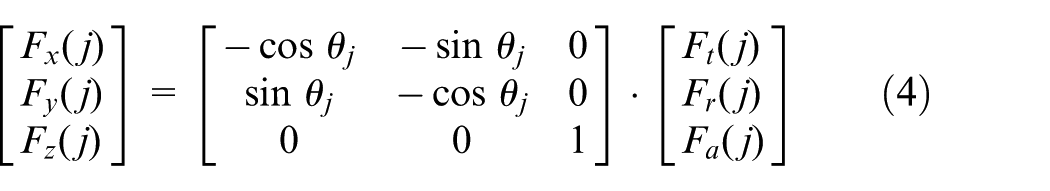
The cutting force in CS1 system transformed into CS0 system can be shown as follows
Instantaneous radial cutting chip thickness
Figure 3 shows the dynamic representation of the cutting insert. From Figures 2(b) and 3, it can be seen that when the jth cutting tooth rotates θj, Δr is the displacement in the r direction comprising rjc (displacement for cutting tooth) and rjw (displacement for workpiece). Δz is the displacement in the Z-direction comprising zjc (displacement for cutting tooth) and zjw (displacement for workpiece) and can also induce radial displacement. γL is the main cutting edge angle. Suppose Δr−1 comprising rjcl and rjwl are the displacements in the r direction between the cutting tooth and workpiece for the j − 1th cutting tooth. fjt is the displacement of tangential cutting force Ft.
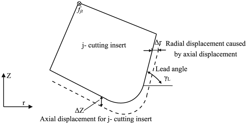
Dynamic representation of the cutting insert.
The radial cutting force in the r direction can be recognized as the sum of static cutting force and dynamic cutting force. The radial displacement r(θj) in the r direction for the jth cutting tooth can be expressed as
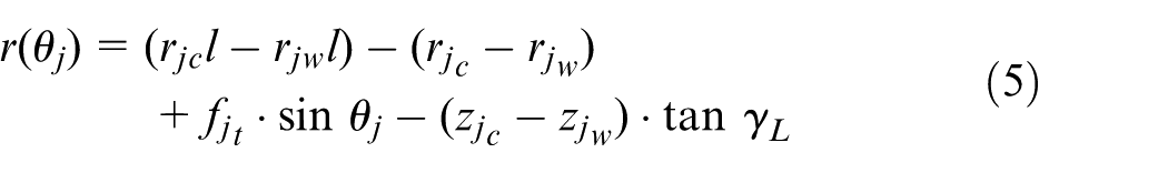
When the jth cutting tooth is at rotation angle of θj, xjc, yjc, xjw and yjw are the displacements in the X- and Y-directions in CS0 system for cutting tooth and workpiece cutting layer. xjcl, yjcl, xjwl and yjwl are the residual displacements of the j − 1th cutting tooth. Equation (5) can be transformed into CS0 system
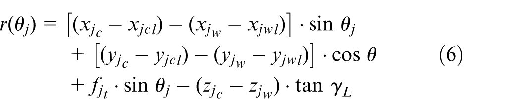
Equation (6) shows the instantaneous milling chip thickness in the radial direction.
Dynamic cutting force model
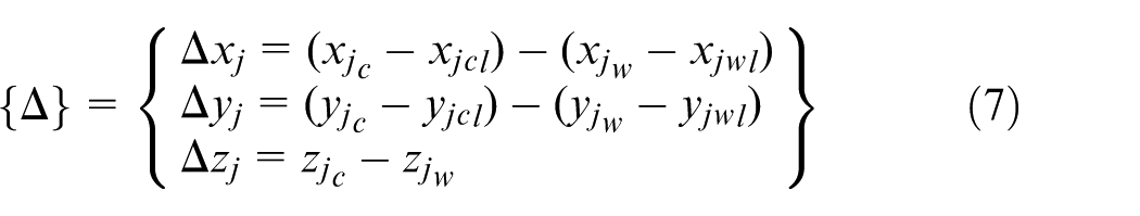
In order to simplify equations (5) and (6), the dynamic relative displacement between cutting tooth and workpiece cutting layer in the X-, Y- and Z-directions can be regarded as
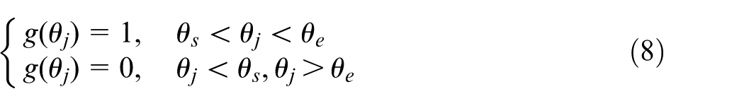
The angular position of the cutting tool at entry point is θs and at exit point is θe. The step function g(θj) is
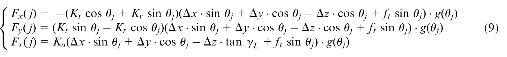
According to equation (6), the cutting force for an individual cutting tooth shown in equation (4) can be changed into
Equation (9) can also be expressed in matrix form as follows
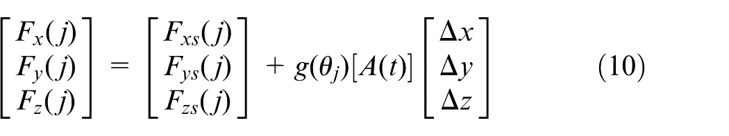
where Fxs(j), Fys(j) and Fzs(j) are the static cutting forces. [A(t)] is the matrix of dynamic cutting force coefficient as shown in equation (11)

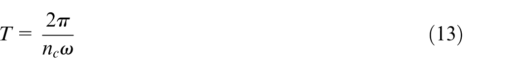
where all the variables in equation (11) have been defined before. Now nc is the number of cutting tool inserts, with ω representing the rotation frequency of face milling cutter, T representing face milling cutter rotation period and ωt representing face milling cutter insert’s rotation frequency which gives

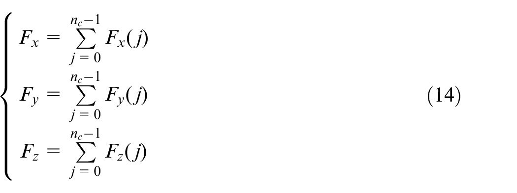
The total cutting force at an arbitrary given rotation angle θ is the sum of individual cutting tooth as shown in equation (14)
Suppose the step function g(θj) is considered in [A(t)], and each matrix element can be stackable. Equation (10) can be simplified as shown in equation (15)

where Fs is the total static cutting force.
In a face milling cutting process, cutting force is induced by dynamic displacement between the cutting tooth and workpiece cutting layer. The dynamic cutting force also induces regenerative chatter. Hence, for stability analysis of face milling processes, the effect of static cutting force can be neglected.
The dynamic cutting force Fd can be expressed as

where [A(t)] reflects the features of face milling process: intermittent, time-varying and periodic.
Prediction of face milling stability
For
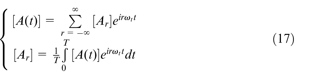
The average of the Fourier series expansion is recognized as [Ao]12,13
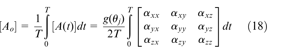
By changing time-domain integration into frequency-domain integration, where θ = ωt, equation (18) can be replaced as
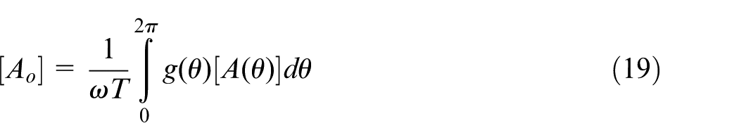
when θs < θ < θe, g(θ) = 1. [Ao] can be expressed as

When only considering the vibration at flutter frequency ωc, the displacement for face milling cutter and workpiece can be calculated as follows


The dynamic relative displacement shown in equation (7) can also be written as
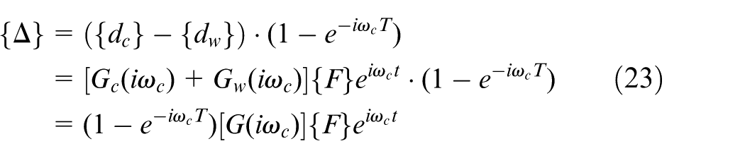
From equations (21)–(23), equation (16) can be expressed as

where [G(iωc)] is the 3 × 3 transfer function matrix.
In X–Y plane, there is always regenerative chatter. The face milling cutter not only rotates but also does linear feed movement at a certain speed.
The impact factor for regenerative chatter µ is
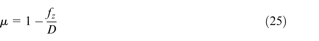
where D is the cutting tool diameter, and fz is the feed per tooth.
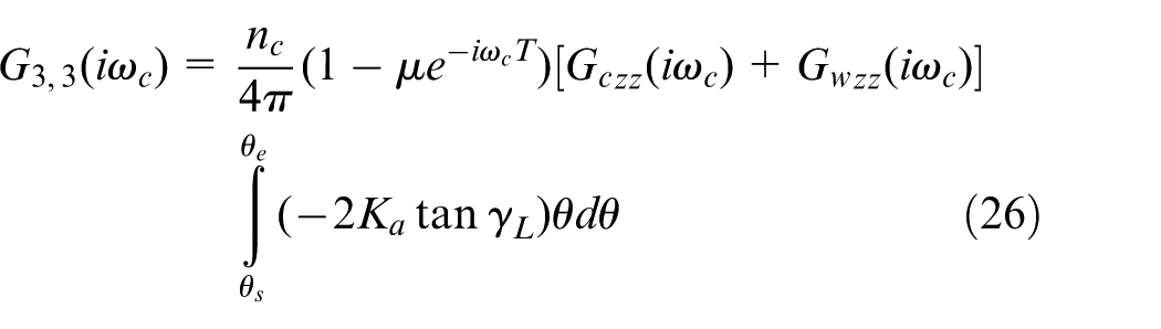
If µ < 0, then let µ = 0. µ only affects the factor of G3,3 in matrix [Ao] as shown in equation (26)
The face milling stability domain can be solved according to equation (24). If the determinant has nonsingular solution, the characteristic equation of the closed-loop dynamic face milling system can be expressed as

where [I] is the unitary matrix. The remaining factors including flutter frequency ωc, axial depth of cut ap, cutting tooth number nc, feed per tooth fz and cutting force coefficients Kt, Kr and Ka need to be determined.
At first, an initial value should be given to ap as cutting force coefficient depends on ap. The calculation process is iterative. When the calculation results reach to a certain range, the iterative process ends. So far, the critical axial depth of cut apl can be obtained which can be used to represent the stability of face milling process.
The characteristic equation (27) has real part and imaginary part. Hence, there are two unknown items: ωc and apl
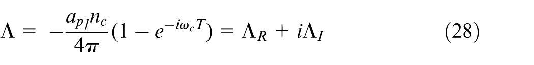
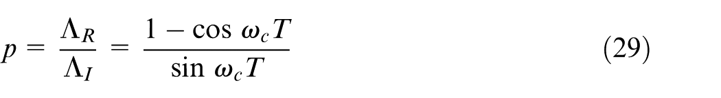
where Λ is the eigenvalue, and p is the ratio of real part and imaginary part.
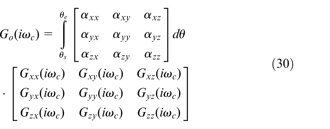
The transfer function matrix
The characteristic equation can be shown

The nonsingular solution for equation (31) is apl
In order to calculate the characteristic value, ωc have to be known.
Under normal circumstances, ωc depends on spindle rotation speed n and the modal parameters of face milling system.
The vibration cycle number for individual cutting tooth is

where k is the largest possible integer, and such that ε < 2π.
From equation (33), the phase difference of the stability limit can be expressed
The phase angle φ determined by eigenvalue Λ is defined as
The solution for equation (34) is

where in face milling stability limit diagram, each k corresponds to different stability phase.
Hence, for certain flutter frequency, the stability limit of the face milling system can be determined by critical axial depth of cut according to equation (32). According to the calculated critical axial depth of cut, the face milling cutter rotation period can be calculated according to equation (36).
The number of rotation period of the face milling cutter can also be expressed as
It can be seen that when ωc and k are determined, the spindle speed n can be calculated as shown in equation (38)
According to the above analysis, in a face milling system, when the machine tool, the face milling cutting tool and the workpiece are determined, under certain chatter frequency, the real part and imaginary part of the characteristic value can be obtained from equation (11). Then, according to equations (32) and (38), the critical axial depth of cut apl and the corresponding rotation speed n can be obtained. Based on the selected chatter frequency and lobe number to repeat the above step, the stability domain for face milling process can be determined.
Prediction of the stability limit lobes for face milling process
By using frequency-domain method to establish the stability domain lobes, the stable region and unstable region can be separated rapidly.
Identifying modal parameters for face milling system
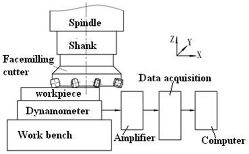
The main modal parameters that affect the stability limit lobes include modal mass, modal stiffness, modal damping and natural frequency. Hence, the identification of these parameters is necessary to model the dynamic characteristics. Figure 4 shows the principle of the modal test. The modal tests were conducted on VMC0540d vertical machine center which has an installed HSK63A holder and face milling cutter as shown in Figure 4.
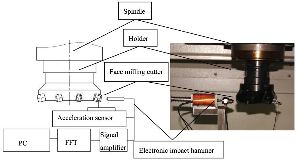
Modal test system for face milling system.
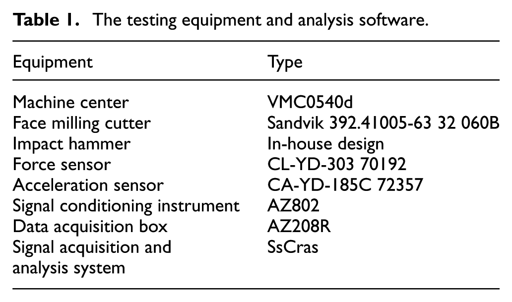
Table 1 shows the components of the modal experimental setup.
The testing equipment and analysis software.
The real frequency diagram and imaginary frequency diagram of the workbench-workpiece can be obtained and are shown in Figure 5.
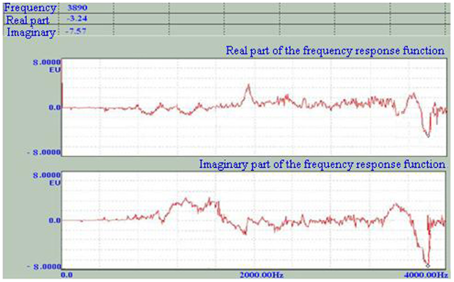
Diagram of real frequency and imaginary frequency for workbench-workpiece.
Figure 6 shows the real frequency and imaginary frequency diagram for “spindle-shank-face milling cutter.”
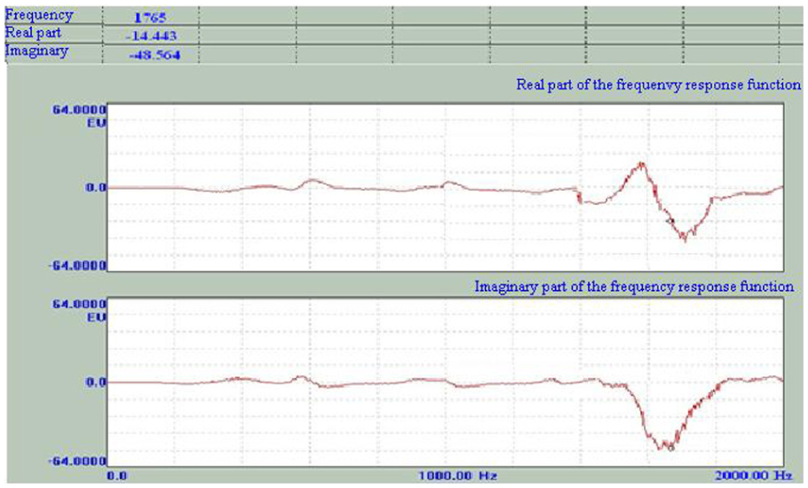
Diagram of real frequency and imaginary frequency for spindle-shank-face milling cutter.
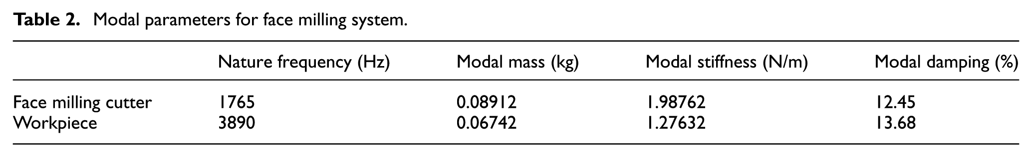
By using component analysis method, the natural frequency, modal mass, modal stiffness and modal damping can be determined and are shown in Table 2.
Modal parameters for face milling system.
Stability limit lobes for face milling system
According to the critical axial depth of cut and the peak point decided by modal parameters, the stability limit lobes can be built as shown in Figure 7. Since the face milling system is a multi-degree freedom system, reflected in FRF, there are several peak points. Taking every peak point as single degree of freedom, the corresponding “stability lobes” can be constructed. The critical axial depth of cut under every spindle speed is reserved, with the left part trimmed off (the dotted line as shown in Figure 7). Then the stability limit diagram can be obtained.
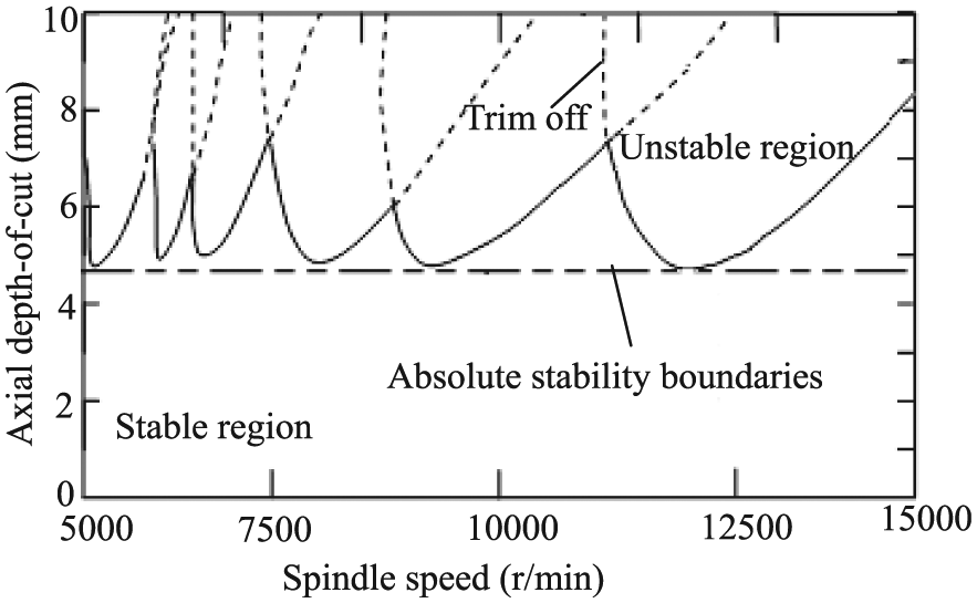
The stability limit lobe for face milling system.
Experimental validation of the stability limit lobes
Design of the experimental system
Milling experiments with proper cutting conditions were conducted based on appropriate cutting angles and other cutting parameters. In this article, cutting force and machined workpiece surface roughness are selected as the characterization to check whether the milling process is stable or not. When the milling process is unstable, the cutting force will increase dramatically, and so does the surface roughness. Workpiece material used for the experiments is an aluminum 7050 alloy.
The cutting force acquisition equipment is Kistler dynamometer (9219AA). The cutting force acquisition system is shown in Figure 8. The sensitivity of the dynamometer in the X-, Y- and Z-directions is 35.59 pC/lbf. The surface roughness and surface morphology are determined by using NT9300 optical surface profiler.
Cutting force measurement system.
Due to the stability limit, lobes reflect the relationship between axial depth of cut and the spindle speed. Hence, in this article, the feed per tooth is set to be constant with the value of 0.12 mm/tooth.
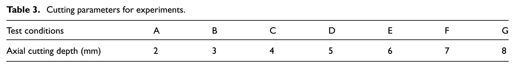
According to the stability limit lobes, the spindle speeds were selected to be 10,000, 12,000 and 14,000 r/min. Seven different axial cutting depths were adopted as shown in Table 3.
Cutting parameters for experiments.
Experiment results and analysis
Figure 9 shows the cutting force changes with axial depth of cut under different spindle speeds.
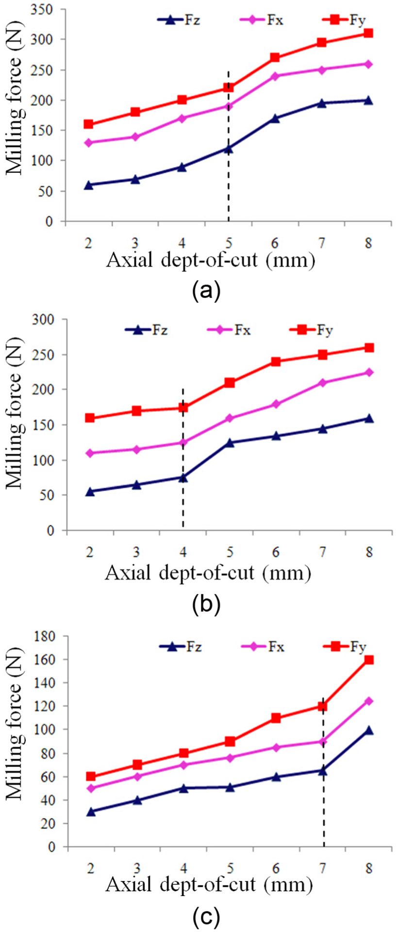
The relationship between cutting force and axial depth of cut under different spindle speeds: (a) spindle speed is 10,000 r/min, (b) spindle speed is 12,000 r/min and (c) spindle speed is 14,000 r/min.
From Figure 9, it can be seen that the cutting force decreases with the increase in spindle speed. This can be explained by increased heat generated at higher spindle speed, which softens the workpiece and makes it easy to cut. The reflection in cutting force is a monotonic decrease. The value of tangential milling force Fy is the largest, followed by the radial milling force Fx and axial milling force Fz which obtained the same trends as Mativenga and Hon. 14
In Figure 9(a), the milling force begins to increase sharply and face milling stability declines when the axial depth of cut was 5 mm at the spindle speed of 10,000 r/min; for Figure 9(b) with spindle speed of 12,000 r/min, the milling force begins to increase sharply when the axial depth of cut reached 4 mm and for spindle speed of 14,000 r/min, the critical axial depth of cut is 7 mm as shown in Figure 9(c).
Figure 10 shows the surface roughness change with axial depth of cut under different spindle speeds.
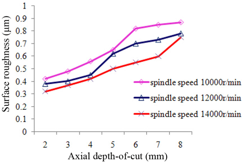
Surface roughness change with axial depth of cut under different spindle speeds.
From Figure 10, it can be seen that surface roughness generally increases with the increase in depth of cut and decreases with spindle speed. For spindle speed of 10,000 r/min in stable cutting region (axial depth of cut smaller than 5 mm), the surface roughness changes gently. Once unstable region (axial depth of cut greater than 5 mm) is reached, the surface roughness changes rapidly, and the surface morphology gets worse as shown in Figure 11. From Figure 10, for spindle speeds of 12,000 and 14,000 r/min, the critical axial depths of cut for dividing the stable region and unstable region of 4 and 7 mm, respectively, can also be seen.
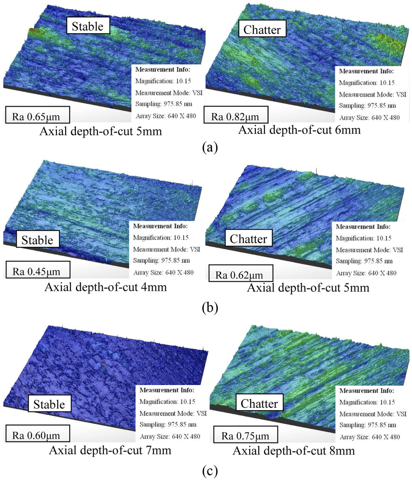
Surface morphology in stable and unstable cutting operations: (a) surface morphology with axial depths of cut 5 and 6 mm under spindle speed 10,000 r/min, (b) surface morphology with axial depths of cut 4 and 5 mm under spindle speed 15,000 r/min and (c) surface morphology with axial depths of cut 7 and 8 mm under spindle speed 14,000 r/min.
Figure 11 shows the surface morphology in stable and unstable cutting operations. As shown in Figure 11, under different spindle speeds, only two cases of the surface morphology are selected to exhibit. One is under the critical axial depth of cut and the other one is under higher axial depth of cut. It can be seen in Figure 11, for the stable cutting region, the surface quality is good; when in the unstable cutting region, most area of the surface has been deteriorated and presents typical chatter surfaces. The surface morphology is intuitive to distinguish the stable and unstable regions.
Figure 12 shows the stability limit lobe for face milling system. The seven points A, B, C, D, E, F and G represent seven different axial depths of cut 2, 3, 4, 5, 6, 7 and 8 mm when the spindle speeds are 10,000, 12,000 and 14,000 r/min. It can be seen that for spindle speed of 10,000 r/min, A, B, C and D points are in the stable region, and there is no occurrence of chatter phenomena. It begins to have signs of chatter phenomenon when the axial cutting depth reaches 6 mm. While there was occurrence of chatter phenomena when the axial cutting depth reached 6 mm and points E, F and G are in the unstable region. For spindle speed of 12,000 r/min, points A, B and C are in the stable region, and the last four points D, E, F and G are in the unstable region. For spindle speed of 14,000 r/min, the stable region is quite broad and only point G is in the unstable region.
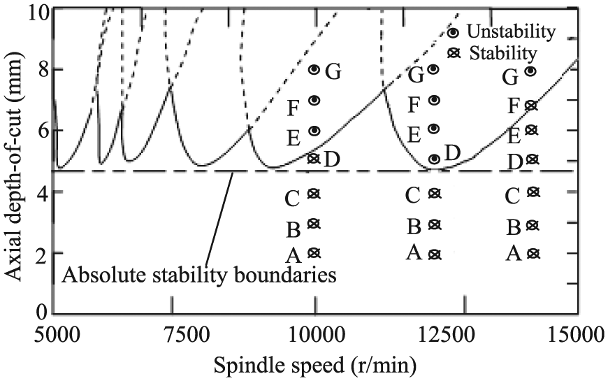
Verification of the stability limit lobes.
The region under the dividing line drawn at the bottom of the boundary of the stable region and unstable region can be treated as the absolute stable region as shown in Figure 12. Under the dividing line, it is a stable cutting area for different spindle speeds. In order to guarantee the stability and efficiency of milling process, the axial depth of cut should be chosen to be under the curve, while the spindle speed should be chosen to be highest possible for the given setup.
Conclusion
An algorithm for predicting the stability lobes for face milling process has been developed in this article. The following conclusions were observed:
The main reason for vibrations is the regeneration of the chip thickness. Based on the instantaneous cutting radial thickness, the dynamic milling force model is created while the coefficient matrix can reflect the discontinuous, time-varying and cyclical change features of the face milling force.
By solving the characteristic equation for dynamic face milling system, the principle that the relationship between axial cutting depth and spindle speed can be used to represent the stable area for face milling system is validated.
Surface roughness generally increases with the increase in depth of cut, while in stable cutting region, the surface roughness changes gently, once the cutting system reaches unstable region, the surface roughness changes dramatically, and the surface morphology gets worse.
Experimental results show that the proposed method is able to calculate the stability lobe with a high accuracy, and based on this, good parameter combination can be determined for high-performance machining process.
Footnotes
Acknowledgements
The authors would like to thank Professor Philip Mathew, Guest Professor, School of Mechanical Engineering, Shandong University for the help with the writing and improving the clarity of the paper.
Declaration of conflicting interests
The author(s) declared no potential conflicts of interest with respect to the research, authorship, and/or publication of this article.
Funding
The author(s) disclosed receipt of the following financial support for the research, authorship, and/or publication of this article: The authors also would like to acknowledge the financial support from the National Natural Science Foundation of China (51505255, 51425503, 51375272, U1201245), the Major Science and Technology Program of High-end CNC Machine Tools and Basic Manufacturing Equipment (2014ZX04012-014), the Specialized Research Fund for the Doctoral Program of Higher Education (20130131120032), China Postdoctoral Science Foundation (2013M540544), the Scientific Research Foundation of Shandong Province Outstanding Yong Scientist Award (BS2013ZZ003) and Independent Innovation Foundation of Shandong University. This work was supported by grants from Tai Shan Scholar Foundation.