
Abstract
Most of the researches on the properties of micro-textured tools are based on an orthogonal test, while the interaction between micro-textured parameters is ignored. Therefore, this thesis is based on an interaction test to study the cutting performance of cutting tools. According to the chip morphology obtained from the interactive test, the micro texture diameter of 60 μm is obtained when the cutting is stable. It was also found that the synergistic effect of multiple mesoscopic geometric features had a significant influence on cutting performance. By analysis, we found the optimized parameters for the milling tool were D = 60 μm, l = 100 μm, l1 = 150 μm, r = 60 μm. Furthermore, prediction models of the cutting performance were established by univariate linear regression and the validity of these models was verified. Thus, this thesis provides a reference for improving the performance of cutting tools and for achieving efficient and high-quality machining of titanium alloys.
Keywords
Introduction
Titanium alloys are materials with physical and chemical properties for aerospace and marine engineering applications. In particular, these materials have stable chemical properties, high strength, and corrosion resistance, which is highly advantageous for aerospace and marine applications. However, titanium alloys also have poor thermal conductivity, a large coefficient of friction and poor wear resistance. Therefore, when machining titanium alloys, the temperature of the workpiece, and the cutting tool rises easily, which can result in adhesion and reduce the lifespan of the cutting tool; accordingly, the machinability of these alloys is poor. In recent years, many studies have identified that the texture of the tool and the tool edge has an important role in reducing friction and improving the machinability of titanium alloys. The main research in this area is summarized below.
Wang et al. 1 and Yang et al. 2 created micro-pit textures in a ball-end milling tool and conducted a three-dimensional simulation for cutting titanium alloys with a micro-textured tool and an ordinary tool. They subsequently analyzed and compared the cutting force required, cutting temperature, and tool wear in the cutting process. The results showed that in dry cutting conditions, the cutting force of the micro-textured tool compared to the ordinary tool was reduced by 16%, the cutting temperature was reduced by 13%, and the wear depth was reduced by 75%. Zhou et al. 3 and Biting 4 conducted tests of dry cutting of 304 austenitic stainless steel with micro-textured compared to the traditional cutting tools. The results showed that micro textures could reduce the stress concentration at the tool edge and change the stress distribution on the rake face. Furthermore, micro-textured, self-lubricating tools significantly reduced the cutting force, the cutting temperature, the friction coefficient, and the wear on the rake face. Cai et al.5,6 studied the influence of tool surface micro textures on tool wear resistance and prolonging tool life. The results showed that surface micro-pit texture can effectively improve tool wear resistance and titanium alloy surface quality. The wear resistance of textured tools is better than that of non-textured tools. The machined surface roughness of textured cutter is lower than that of non-textured cutter. There is a critical value for the influence of the micro-pit diameter of textured tool on the wear resistance of the tool and the roughness of the machined surface. Liang et al. 7 machined micro textures with different structural parameters on carbide rake face, and studied the influence of surface micro textures on cutting temperature and tool wear of carbide tools through cutting test of AL6061 and finite element cutting simulation. The results showed that, compared with the non-textured tool, the cutting temperature of micro-textured tool is obviously reduced, and the high temperature area is obviously reduced. Micro textures on the surface can effectively reduce the bond wear of the rake face, and the transverse texture tool has the best anti-friction and anti-adhesion effect, and the smaller groove spacing is more conducive to reducing the bond wear of the tool. Patel et al. 8 conducted orthogonal cutting tests on the effects of micro-textured tungsten carbide cutting tools on cutting forces, friction coefficient, and tool wear in dry cutting of alloy steel AISI 4340. Distinct effects of microgroove dimensional parameters on specific forces, friction coefficient, and tool wear are reported as tested at varying cutting speeds and feed rates. Increased groove width and spacing reduces chip-tool contact but increases chip flow and adherence into micro-grooves. Sugihara and Enomoto 9 machined groove micro textures on both the rake and flank faces of carbide turning tools, and conducted orthogonal cutting tests on AISI 4140 steel under dry conditions. The results showed that the friction coefficient of the rake and flank faces of micro-textured tools decreased by 17% and 18%, respectively, compared to non-micro-textured tools, and that the bonding contact area of the rake face decreased significantly.
Zheng et al. 10 used simulation software to implement a finite element simulation of milling 45 steel with different blunt tool edges and studied the influence of the different edges on the force, temperature and chip in the milling process. The research showed that with increasing blunt tool edge radius, the cutting force and radius of the chip curl increase, while the cutting temperature first increases and then decreases The cutting temperature was the lowest when the radius of the blunt tool edge was 0.06 mm. Zhang 11 studied the influence of tool edge passivation on cutting temperature by simulated and testal cutting of aluminum alloy 211Z. The research showed that the cutting temperature was the lowest when the feed rate was 0.05 mm/s, the rotation speed was 2000 rpm, the axial cutting depth was 4 mm, the radial cutting depth was 2.5 mm, and the radius of the blunt cutting edge was 24.25 μm. Peng et al. 12 studied the influence of tool edge passivation on the service life of cutting tools by using PCD tools in milling tests of titanium alloys. This study showed that with increasing radius of the blunt tool edge, the service life of cutting tools first increases and then decreases. When the passivation value was 15 μm, the service life of the cutting tools was the highest. Zhao et al. 13 used different blunt tool edges for cutting AISI 52100 steel to investigate the influence of tool edge on the cutting force. The results showed that the geometry of the blunt tool edge has a significant impact on cutting force and performance. In particular, with increasing blunt tool edge radius, the cutting force, and the friction between the tool edge and the workpiece increase. Sartkulvanich 14 conducted finite element simulation of metal cutting through the Engineering Research Centre for Net Shape Manufacturing (ERC-NSM) to study the influence of different tool edges on cutting performance. The study found that with increasing blunt tool edge radius, the cutting and feed forces increase significantly, while the cutting temperature was not significantly affected. Fulemova and Janda 15 studied the influence of different tool edges on the tool lifespan by cutting stainless steel. It was found that the tool lifespan was the long when the tool edge radius was 15 μm. Finally, Zhao et al. 16 cut AISI 52100 steel with tools with different blunt tool edge radii, and studied the influence of tool edge radius on the quality of workpiece surface and tool wear. The results showed that the blunt tool edge radius has significant influence on cutting force, cutting performance, and tool lifespan. In particular, when the radius of the blunt tool edge was 20 μm, the tool wear was the most severe, while the tool wear was minimized when the radius was 30 μm.
Grinding force model, which is on the basis of cutting process of single abrasive grains combined with the method of theoretical derivation and empirical formula by analyzing the formation mechanism of grinding force, was established by Li et al. 17 Lila Imani, Ali Rahmani Henzaki, Reza Hamzeloo, Behnam Davoodiare considered as input parameters for investigation of milling of Inconel 738. Four levels for the two former input parameters and two levels for the two other, totally 64 experiments, were fulfilled and studied. Based on the experimental results, the effect of input parameters on the outputs, that is, cutting force and surface roughness, was investigated, and then, neural network for modeling and predicting and genetic algorithm for the optimization of the outputs have been utilized. 18 Wang et al. established the progressive damage cutting force model of CFRP high-speed milling by ABAQUS, and carried out the experimental verification, analyzed the influence mechanism of fiber direction on cutting force, stress, and material failure in the milling process. The results showed that the error between the established cutting force model and the experimental value was <5%, and the model had high reliability. 19 Bayraktar and Turgut conducted orthogonal array test design experiments for each of with 90°–118°and 135° point angle uncoated, TiN and TiAlN coated HSS drills. Select three different cutting speeds (100–125–150 m/min) and feed rate (0.1–0.2–0.3 mm/rev) values as cutting parameters. The research found that uncoated drills caused less delamination than TiN and TiAlN coated HSS drills and optimum cutting parameters were determined as the high cutting speed, low feed rate and drill point angle combination. 20 Bayraktar and Turgut conduct a experiment of milling a carbon-fiber-reinforced polymer composite material (CFRP) using various carbide end mills which based on the Taguchi L-18 (6(1) × 3(2)) orthogonal array. With the analysis of variance (ANOVA), the feed-rate factor was found to be the most effective one among these parameters (cutting forces and surface roughness).The results of the experiments showed that the uncoated carbide end mill had a better performance in terms of the cutting forces and surface roughness. 21 Chen et al. demonstrated a nested-ANN (Artificial Neural Network) model predicting surface roughness (Ra). The enclosed-ANN models used cutting parameters as inputs to predict the values of cutting forces and tool vibrations respectively, and then forward all outputs to the output-ANN model Subsequently, the output-ANN adopts the forward values and cutting parameters as inputs to predict Ra. And compared with mathematical and statistical models based on conventional ANN and RSM (Response Surface Methodology) using the same experimental data. The results showed that the nested-ANN uses less input variables to obtain superior prediction accuracy than other models. Additionally, the statistical analyze show that Ra is mostly affected by the feed rate and has a signification correlation with the feed rate, the cutting force in both radial and tangential directions as well as the tool vibrations. 22 Bayraktar and Afyon carried out machinability experiments in CNC vertical machining center under dry cutting conditions using uncoated carbide drill and constant cutting speed (120 m/min), feed (0.15 mm/rev), and depth of cut (15 mm) values. Experimentally observed that the microstructure of Al–7Si binary alloy is composed of aluminum-rich α phase, primary silicon crystals and eutectic Al–Si phase. The addition of 4% Zn to the Al–7Si alloy did not form a different phase in the microstructure. However, Al2Cu intermetallic phase was formed by addition of 3% Cu. While the hardness and tensile strength of the alloy increased, elongation to fracture significantly reduce. 23 Zhang et al. proposed a new prediction model to forecast the temperature distribution on the rake face based on the heat source theory, and carried out with several cutting tests by monolayer coated tools in the machining of H13 hardened steel. It is found that the rake face temperature in monolayer coated tool for machining H13 shows an increase trend as the cutting speed increases. 24 Bayraktar and Demir conducted a cutting tests performed by using different cutting speeds-CS (450–500–550 m/min), feed rates-FR (0.05–0.15–0.25 mm/rev) and constant depth of cut-DOC (1.5 mm). Selected Uncoated (A), CVD-TiCN + TiN (B), and PVD-TiAlN + TiN (C) coated carbide inserts as a cutting tool. The cutting tests result show that, it was detected that the cutting force (CF) reduced with T6 heat treatment at all CS and FR values. The CF, BUE (Built up edge), and BUL (Built up layer) heightened with increasing FR, while it reduced with increasing CS on all cutting tools. CF, BUE, and BUL were formed at least in tools A, B, and C, respectively. 25 Tebassi et al. developed a models based on three-level Box-Behnken design (BBD) of experiments with 15 experimental runs composed of three center points, conducted on Inconel 718 work material using coated carbide insert with cutting speed, feed rate, and depth of cut as the process parameters under dry environment. Results show that the ANN prediction model provides a maximal benefit in terms of precision of 10.1% for cutting force (Fv) and 24.38% for surface roughness (Ra) compared with the RSM prediction model. Artificial neural network (ANN) compared with RSM is a better reliable and accurate approach for predicting and detecting the non-linearity of surface roughness and cutting force mathematical models in terms of correlation and errors. 26
In conclusion, the characteristics of blunt tool edges and micro textures have been shown to impact the cutting performance of a tool. To date, most studies have only analyzed the influence of one point of view on cutting performance. Accordingly, there are few studies investigating whether optimizing both tool edge geometry and micro-texture can further improve the cutting performance of the tool. The distance between the tool edge and the first micro-textured pattern influences the synergistic effect of these two features. Therefore, the orthogonal cutting method is not suitable for testal study of the cutting performance of the tool. By using an interactive test method instead, the influences of various factors are comprehensively considered, so as to reveal the actual influence of mesoscopic geometric characteristics on the chip formation and the cutting performance. The purpose of this study was to optimize the cutting performance of the tool to potentially achieve high-quality and high-efficiency machining of titanium alloys.
Influence of mesoscopic geometric characteristics on chip formation
Test conditions
The test adopts VDL-1000E three-axis vertical milling machine. Measuring milling force with Kistler 9257 dynamometer. The workpiece material was Ti6Al4V titanium alloy and its size was 158.8 mm × 14 mm × 84.5 mm. It was found that when the inclination angle was 15 and the milling method was down milling, the cutting tool can obtain excellent cutting performance. 27 Micro textures was processed by fiber laser in YG8 cemented carbide ball-end milling cutter with diameter of 20 mm, rake angle of 0° and rake angle of 11°. The tool and workpiece size model are shown in Figure 1. The preparation process is shown in Figure 2. The cutting parameters were: cutting speed was 120 m/min; the feed per tooth was 0.3 mm; the cutting width was 0.5 mm; the cutting thickness was 0.3 mm; the processing environment was dry. 28
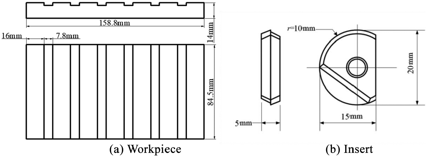
Test sample and cutting tool.
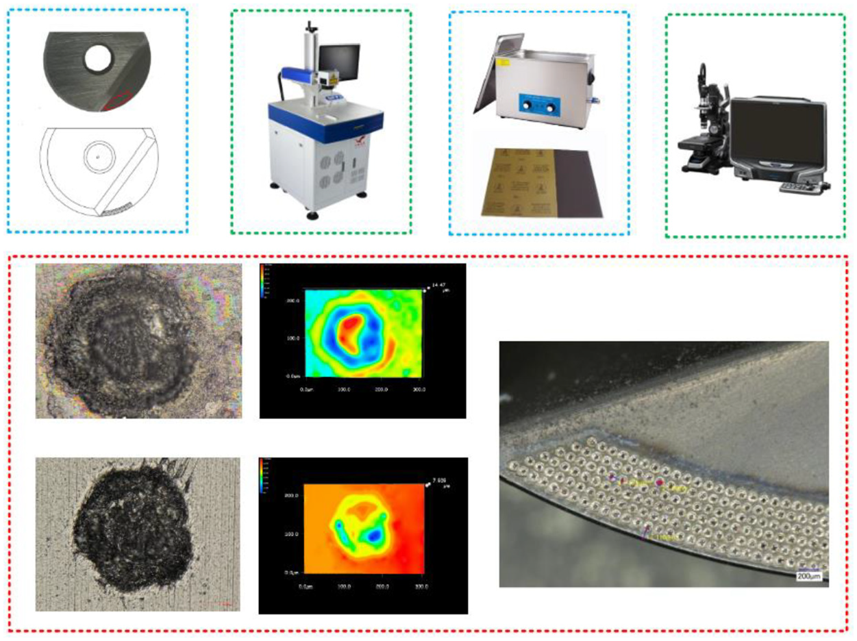
Preparation process of micro-textured ball end milling tool.
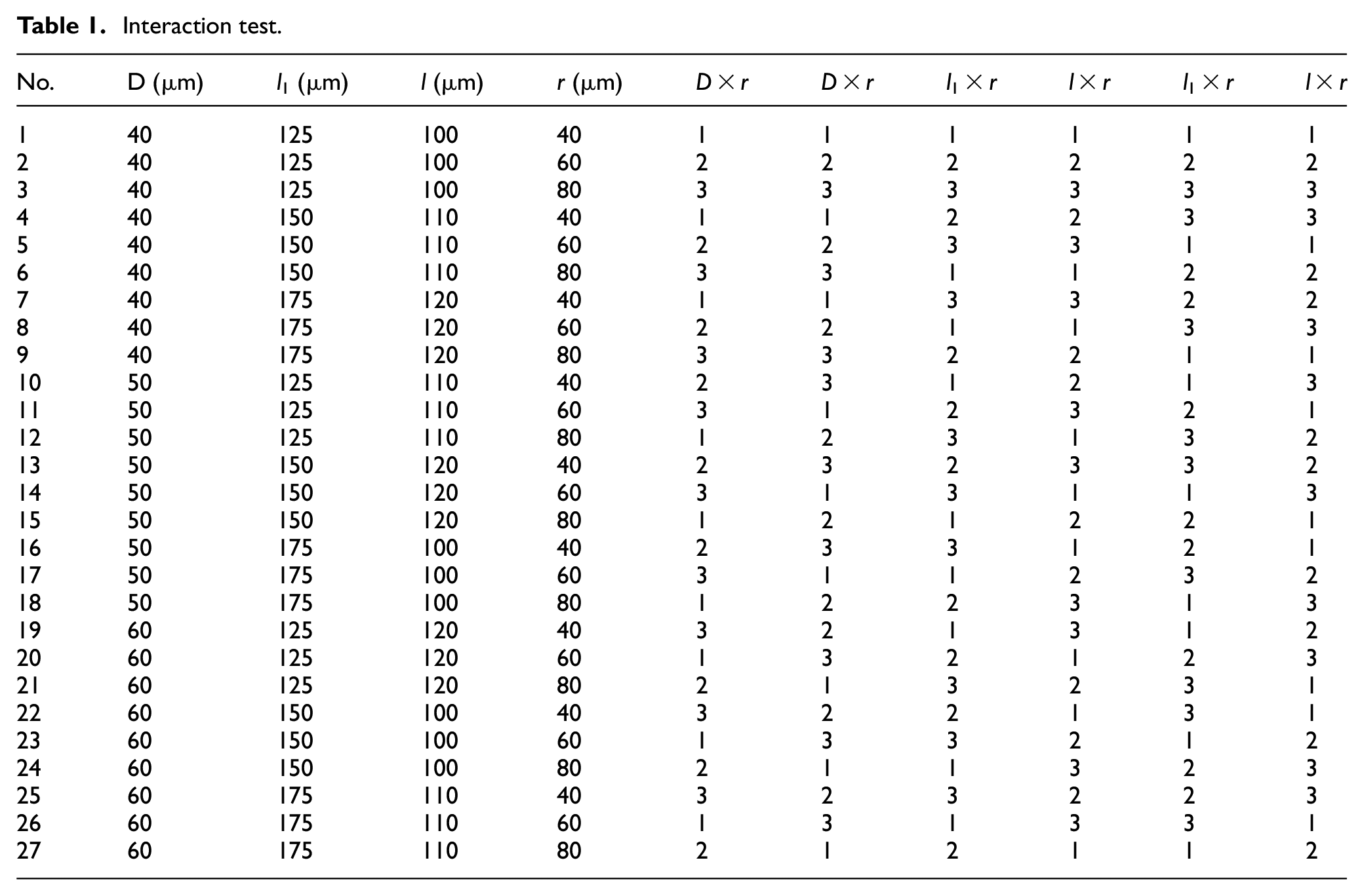
It is assumed that the diameter of a micro texture is D (μm), the distance between the two adjacent micro textures is l1 (μm), the distance between the first row of the micro texture is l (μm), and the radius of the blunt edge is r (μm). The results showed that the range of D is 40–60 μm, the range of l1 is 125–175 μm, the range of l is 100–120 μm, the range of r is 40–80 μm, the cutting performance of micro-textured ball milling tool is the best. 28 Design interaction test with the above parameters as factors, respectively measure milling force F (N), tool wear VB (μm) and workpiece surface quality Ra (μm) under the action of mesoscopic geometric features, as shown in Table 1.
Interaction test.
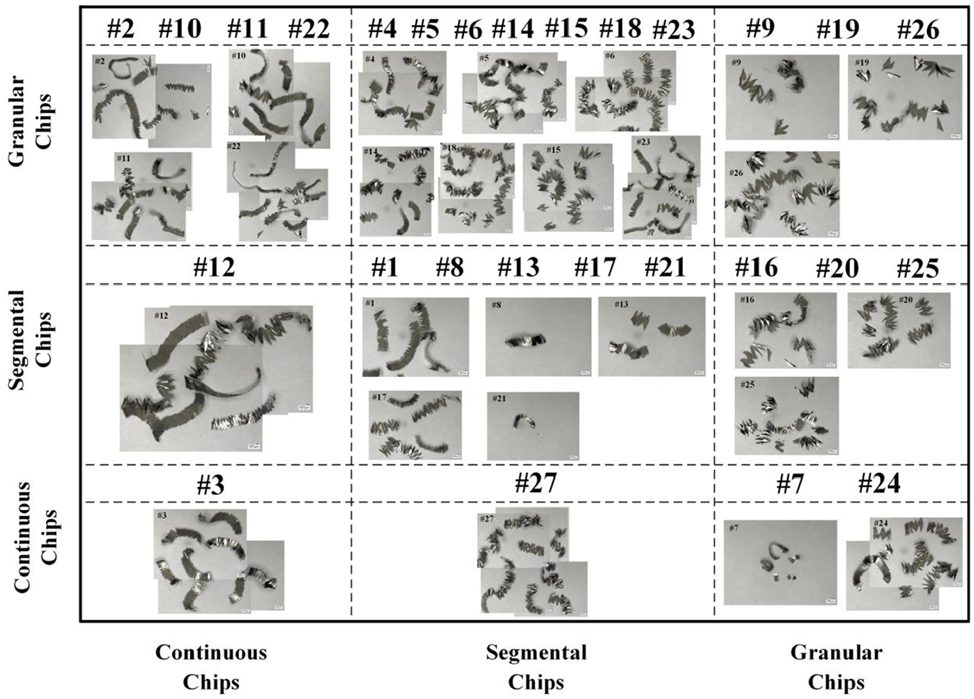
Chip formation
The chip generated by each group of tests is collected. In this test, single tooth intermittent cutting is adopted. The radius of tool rotation and the linear speed are both small. Therefore, under the influence of milling force and tool wear, the types of chips are mainly divided into continuous chips, segmental chips, granular chips. The results showed that the cutting process of strip chip is the most stable, and the fluctuation of cutting process is the biggest when granular chip is formed. As shown in Figures 3 and 4, it can be seen from the table that when the micro texture parameters are the same, except for groups 7–9 and 16–18 whose distance from the edge is 175 μm (milling process instability caused by the sudden change of milling force and tool wear state between two adjacent groups), the cutting process tends to be stable with the increase of the radius of blunt tool edge. When the radius is 60 μm, no matter what the distance between the micro texture and the edge is, the cutting process tends to be stable with the increase of the radius. Therefore, the diameter of the micro texture is 60 μm for the purpose of cutting stability.
Chip formation.
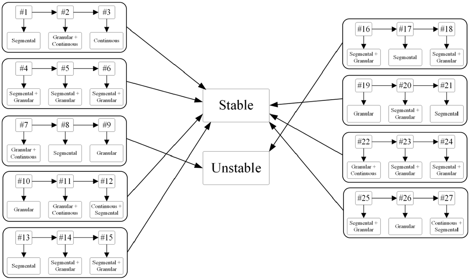
Stability of cutting process changes with the tool edge radius.
Analysis of mesoscopic geometric characteristics on the cutting performance
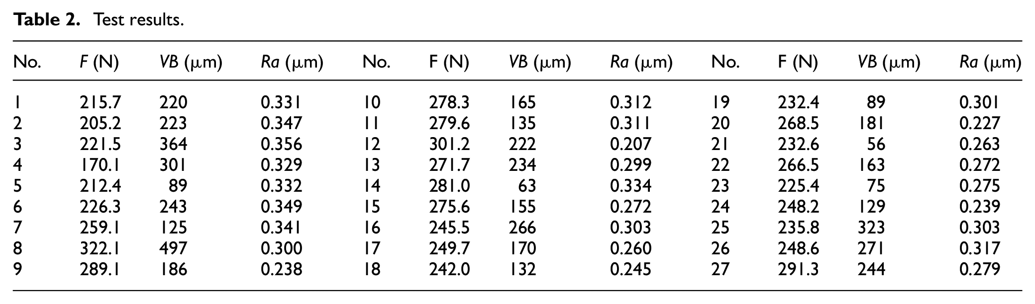
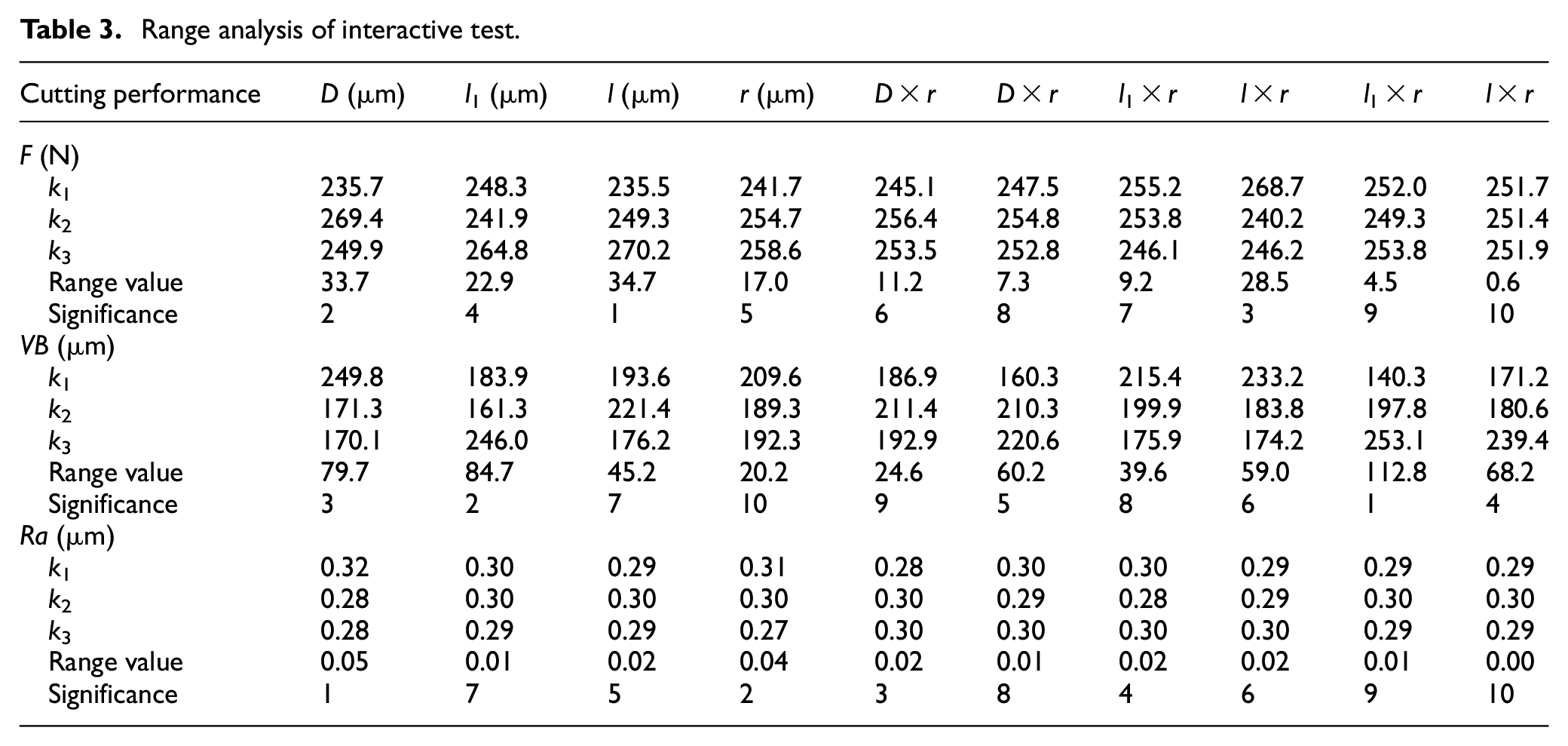
Test results are shown in Table 2. The results were analyzed by range analysis. It can be seen from Table 3 that the main factors that have significant influence on milling force are: l, D, l × r, and l1. The main factors that have significant influence on the tool wear are: l1 × r, l1, D, and l × r. The main factors that have significant influence on the surface quality of workpiece are as follows: D, r, D × r, and l1 × r.
Test results.
Range analysis of interactive test.
In Figure 5, with the increase of l, the number of micro textures in the tool-chip contact area decreases, which results in the increase of F. With the increase of D, phenomenon of secondary cutting is generated between chip and the edge of micro textures, so F increases first. With the increase of D, the number of micro textures on the rake face decreases, the surface roughness of the tool decreases, the friction force decreases, which is larger than the milling force increases in the second cutting, so F decreases later, and VB decreases first and then maintain stable. Ra decreases because of the anti-wear and an-tifriction effect of micro textures. With the increase of r, Ra decreases because of the increase of the radius of the blunt edge, which makes strength of the tool edge increase. With the increase of l1, the number of micro textures on the rake face and the surface roughness of the tool decreases. Therefore, F and VB decrease first and then increase. With the increase of the interaction between l × r, force decreased by the tool edge is much greater than that increased by the decrease of effect of micro textures, so F decreases with the increase of interaction between l1 × r and l × r, the number of micro textures in the tool-chip contact area is less and less, and the anti-wear and anti-friction effect of micro textures is continuously weakened, which makes VB increase in both cases. With the increase of interaction between D × r, the number of micro textures decreases, the ability of micro textures to capture chips decreases, and the force increased by the tool edge is far less than that decreased by the weakened effect of micro textures, so Ra increases. With the increase of effect interaction of l1 × r, Ra basically maintains stable.
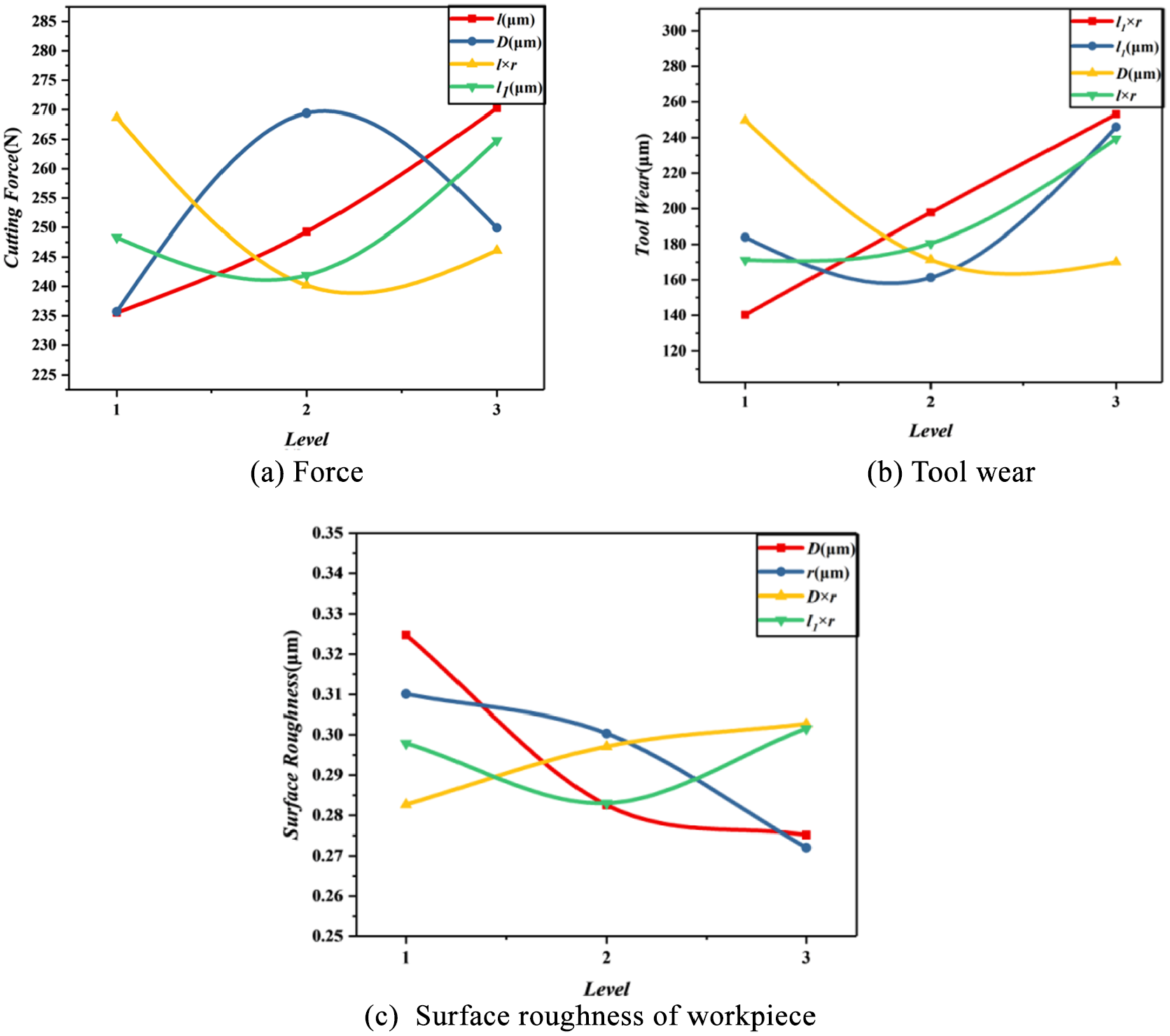
Influence of mesoscopic geometry on cutting performance of ball end milling tool.
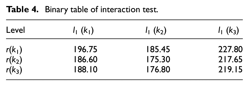
The most important factor affecting the milling force is l, so it can be seen from Figure 5 that when l = 100 μm, the milling force is the minimum. The most important factor affecting the tool wear is l1 × r, so it is necessary to optimize the parameters by binary table and binary diagram. As shown in Table 4 and Figure 6, when l1 = 150 μm, r = 60 μm, the tool wear is the smallest. The most important factor affecting the workpiece surface quality is D, when D = 60 μm, the surface roughness of workpiece is the smallest. To sum up, considering all factors comprehensively, we can get the optimal scheme as follows: D = 60 μm, l = 100 μm, l1 = 150 μm, r = 60 μm. The optimization results are the same as those obtained by chip optimization.
Binary table of interaction test.
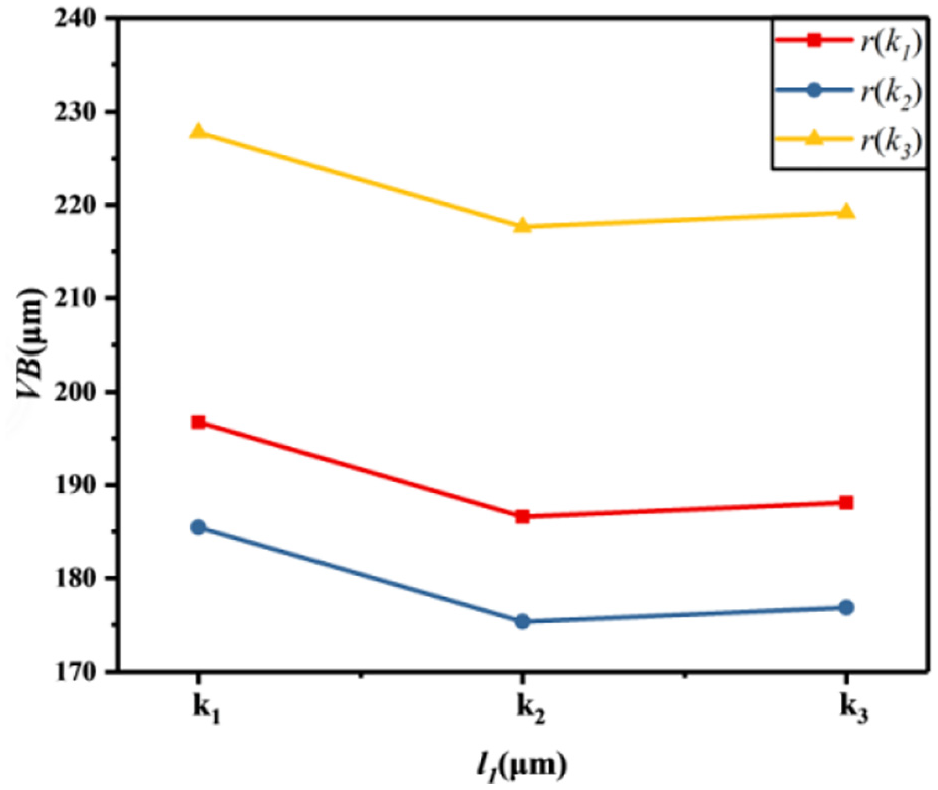
Binary diagram.
Prediction models of cutting performance of ball end milling tool with mesoscopic geometric characteristics
Optimization of target data based on support vector machine
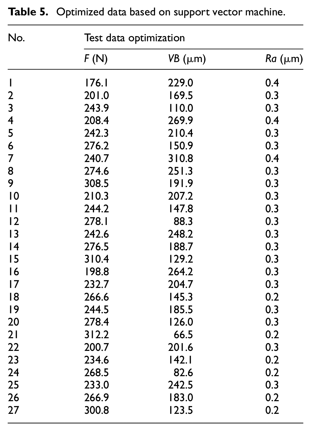
Loss functions to establish support vector regression models are the same as literature. 29 Support vector regression machine and MATLAB are used as tools to optimize the evaluation index of micro-texture ball-end milling cutter. The support vector regression machine type is SVM, and the kernel function type is Gaussian kernel function. The gamma function is 0, the penalty coefficient is 106, the parameter of v-SVR is 0.5, the loss function of e-SVR is 0.1, the memory size is 100 MB, and the allowable termination error is 0.001. The data optimized by the support vector regression (SVR) for design parameters of micro-textured ball-end milling tool under the action of different tool edge are shown in Table 5.
Optimized data based on support vector machine.
Prediction models established by univariate linear regression
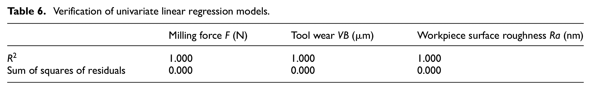
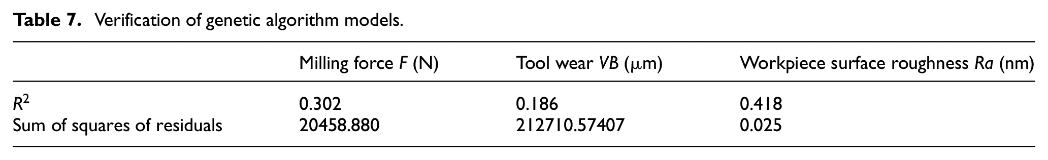
In this paper, micro-pit diameter is D, distance between adjacent two micro textures is l1, a row of micro-pit textures distance from the tool edge is l, and the blunt tool edge radius blunt edge is r. According to the prediction model optimized by support vector regression machine, the linear regression mathematical model established by origin is used to observe the fitting results as shown in Table 6. The fitting results of genetic algorithm model observation are shown in Table 7.
Verification of univariate linear regression models.
Verification of genetic algorithm models.
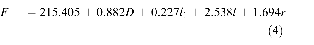
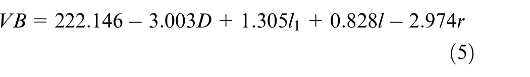
Based on origin analysis, it is concluded that the linear regression models optimized by support vector regression machine almost completely fit the testal data and presents a linear regression relationship. Assuming that the independent variables are D, l1, l, r, and the dependent variables are F, VB, Ra, and a represents a series of constants, the prediction models can be obtained as follows.


Then the cutting force F, tool wear VB and workpiece surface roughness Ra optimized by support vector regression model are substituted into the above formula, and the prediction models are as follows.

In order to analyze the fitting degree more intuitively and conveniently. The genetic algorithm models, linear regression models and testal data are fitted into broken line graph and scatter plot, as shown in Figure 7.
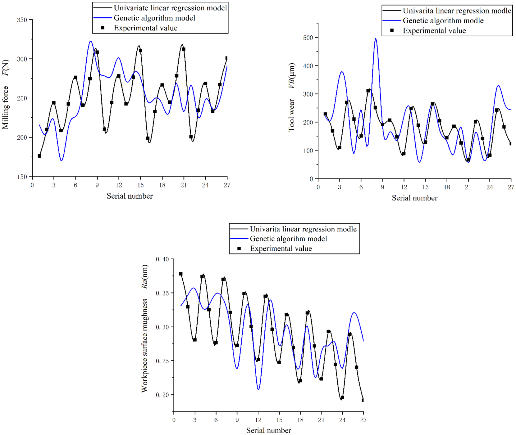
Fitting analysis effect.
According to the fitting curve in the graph, the univariate linear regression models are completely fitted with 27 groups of testal data, and the effect is ideal. However, there is a big deviation between the genetic algorithm models and 27 groups of testal data. From the fitting effect of the second group of graphs to VB, it can be found that the linear regression models are much better than the genetic algorithm models.
Conclusion
An interactive milling test platform was established and the formed chip is obtained. It is found that except for the testal group whose distance from the edge is 175 μm, the cutting process of the other testal groups tends to be stable with the increase of the tool edge radius, so the diameter of the micro texture is selected as 60 μm.
The influence of the synergistic effect of multiple mesoscopic geometric characteristics on the cutting performance of a ball end milling tool was investigated. Secondary cutting and rake surface roughness will affect milling force, tool wear and workpiece surface quality. The optimal mesoscopic geometric parameters were D = 60 μm, l = 100 μm, l1 = 150 μm, r = 60 μm, which lay the foundation for improving the cutting performance of the tool and in turn, achieving high-quality titanium alloy machining.
Based on support vector machine, the test data was optimized and prediction models of the cutting performance of ball end milling tools with different mesoscopic geometric features were established under the condition of two modeling methods. Furthermore, the validity and accuracy of these models were verified and a method for efficient machining of titanium alloys was demonstrated.
Footnotes
Declaration of conflicting interests
The author(s) declared no potential conflicts of interest with respect to the research, authorship, and/or publication of this article.
Funding
The author(s) disclosed receipt of the following financial support for the research, authorship, and/or publication of this article: Thanks for the support of the National Natural Science Youth Fund (52005410).