
Abstract
This article studies two types of assembly tasks, namely snap-fit insertions and press-fit hose insertions. Experimental data and theoretical modelling of a snap-fit assembly are used to design a tool that can perform the snap-fit task effectively. The design process of the tool is presented and experimental tests developed to validate its effectiveness are described. Hose insertion experiments are then performed and the results are analyzed in order to develop strategies for the effective insertion of press-fit components in assembly tasks. A motion primitive strategy is first explored, followed by a vibration oriented strategy. Finally, a video demonstrating the experiments accompanies this paper.
Introduction
Assembly is a major part of the tasks performed in industrial manufacturing. Although assembly is still often performed manually, actuated mechanisms are being introduced to improve quality and productivity while decreasing the human effort required and ease the task of human operators. This work is part of a more global research initiative that aims at developing assistive devices to help operators to perform assembly tasks. The development of tools and devices to handle the parts to be assembled is a major challenge in the project. Grippers1,2 and position and orientation correcting mechanisms are considered. Among existing architectures of such mechanisms, six-degree-of-freedom architectures such as the one proposed in Abtahi et al. 3 are often considered for their high dynamic output. Monsarrat and Gosselin 4 presents an effective architecture based on actuated revolute joints. Carretero et al. 5 presents a compact architecture where all the actuators are placed on the fixed frame. Machining architectures are also interesting for their robustness, for instance6,7 present very stiff mechanisms.
This work presents a design analysis and an experimental validation of tools for snap-fit and press-fit type assembly tasks. Snap-fit and press-fit are a class of assembly tasks that consist in the elastic deformation of at least one of the components to ensure a proper link between the parts involved based on their shape. Therefore, performing this kind of assembly requires to cross the elastic deformation energy threshold of the deformed parts. Measuring this energy transfer can provide reasonably reliable data to guarantee the success of insertion tasks. Several articles deal with snap-fit assembly tasks such as Luscher et al. 8 where a model to describe snap-fit assembly motion is proposed, Baek et al. 9 where methods to use snap-fit assemblies for microscopic objects are explored and, Rónai and Szabó 10 which investigates a method to perform a snap-fit task on a battery with a robot and the use of a force sensor.
This paper is structured as follows. First, the snap-fit assembly task used as an example task in this work is described. Then, the mechanics of snap-fit tasks using the concepts of energy and momentum are explored. An impactor designed to perform snap-fit assembly is proposed and analyzed in the following sections. Afterwards, a prototype of the impactor is described, followed by an experimental validation. Then, the press-fit insertion of hoses is discussed, which is the second example task used in the paper. A strategy based on motion primitives for the insertion of hoses is then proposed and illustrated as well as an investigation of the use of vibrations to perform such insertions. A video demonstrating the concepts presented in the paper is introduced and commented in the last section.
Snap-fit assembly tasks
The parts chosen to illustrate a snap-fit assembly are shown in Figure 1. The black coloured plastic part assembles on the white painted metal part underneath it through three ‘Christmas tree’ shaped plastic modules. This assembly is mounted on a car door and is a support for the control sensors and motors of the window. Three Christmas trees are used for the assembly: two at the top on each side and one at the bottom, indicated with the letter ‘(a)’ in Figure 1. In this picture, the two Christmas trees at the top correspond to an incomplete assembly, the tree not having crossed the trim, and the one at the bottom corresponds to a completed assembly, the tree being entirely visible. Two other snap-fits are visible at the middle top (indicated with the letter ‘(b)’ in Figure 1). They are used to mount another part on top of the trim whose purpose is to carry other electric components for the actuation. The trees are metallic in this case and do not require the same force to be deformed but their behaviour is the same as that of the plastic ones.
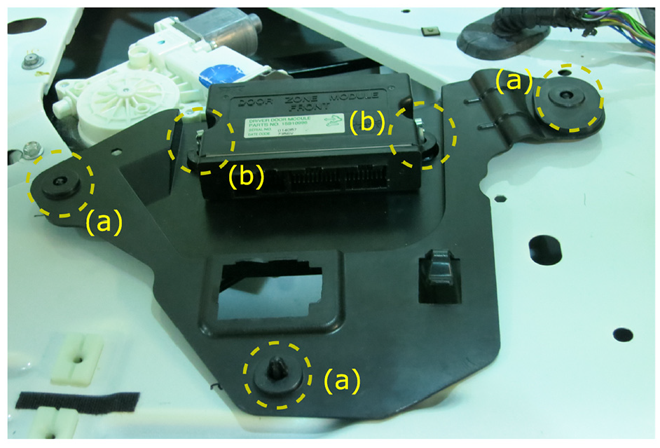
Example of snap-fit assembly. This example is taken from a car door assembly. The areas where the deformations occur are shown with the dashed-line circles. (a) Indicates the ‘Christmas trees’ used to mount the trim on the car’s door and (b) indicates the ‘Christmas trees’ used to mount additional electric components.
The second part of this article deals with hose assembly tasks. Specific devices to help performing hose assembly tasks can be found, for instance in Jahanian et al. 11 Because the task of inserting hoses appears more challenging than snap-fit tasks, a deeper analysis is completed before undertaking the design of a tool, and the result of this analysis is presented here. Measurements performed on assembly tasks can be found for example in Godin et al. 12 Finding appropriate insertion motions, as presented in Grieshaber et al., 13 could be very beneficial for robots because they can efficiently produce consistent motions that make an effective motion strategy even more important.
Finally, Wang et al. 14 and Grieshaber and Armstrong 15 study the force perception during a hose insertion for ergonomic purposes. These works have provided inspiration for the approach proposed in this paper.
Based on an analysis of the snap-fit and press-fit tasks, it is desired to develop new assembly tools and strategies that are less strenuous for human operators in order to reduce ergonomic stress. In the case of the snap-fit assembly studied in the first part of the paper, a tool is developed to produce impacts since impacting the components is deemed the best strategy for insertion. In the case of the press-fit assembly studied in the second part of the paper, several strategies (types of relative motion) are possible and one of the objectives is to relate the different strategies to the fundamental analysis of the mechanics of the operation. The tool developed in the first part of the paper is associated with one possible effective strategy to perform the insertion of snap-fit and press-fit components.
Characterization of insertion tasks
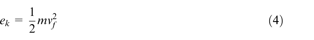
Preliminary work for the design of a device to perform insertion tasks consists in identifying the main parameters that affect the performance of the assembly. Two different fundamental quantities are considered in this analysis, namely momentum and mechanical energy. Momentum is often used to analyze collision problems in order to predict the kinematic behaviour of the bodies involved. Indeed, in a closed system with an inertial frame, the total momentum of the bodies in the system is the same before and after the collision (conservation of momentum). Since the insertion is performed using collisions, it can be assumed that momentum is conserved. The second quantity that is used in the analysis is mechanical energy. Although energy is not necessarily conserved in a collision, this concept can be used to infer the behaviour of a mechanical system. Also, assuming conservation of energy provides useful approximations. In order to investigate the relevance of these two concepts in an insertion operation, an example of a snap-fit insertion is studied. The two parts are represented schematically in Figure 4. The conical part is commonly referred to as a ‘Christmas tree’ component, to be inserted (snap-fit) into the hole of the second part, referred to as the ‘trim to assemble’. As a first experiment, the conical component is placed over the hole and objects of known mass are dropped on it from a measured height until the height is sufficient to perform the insertion. Three different round shaped objects are used. It is assumed that all the potential energy of the dropped object is transferred to the part, to cross the elastic deformation energy threshold. The equations used to compile the experimental results are the following:


with
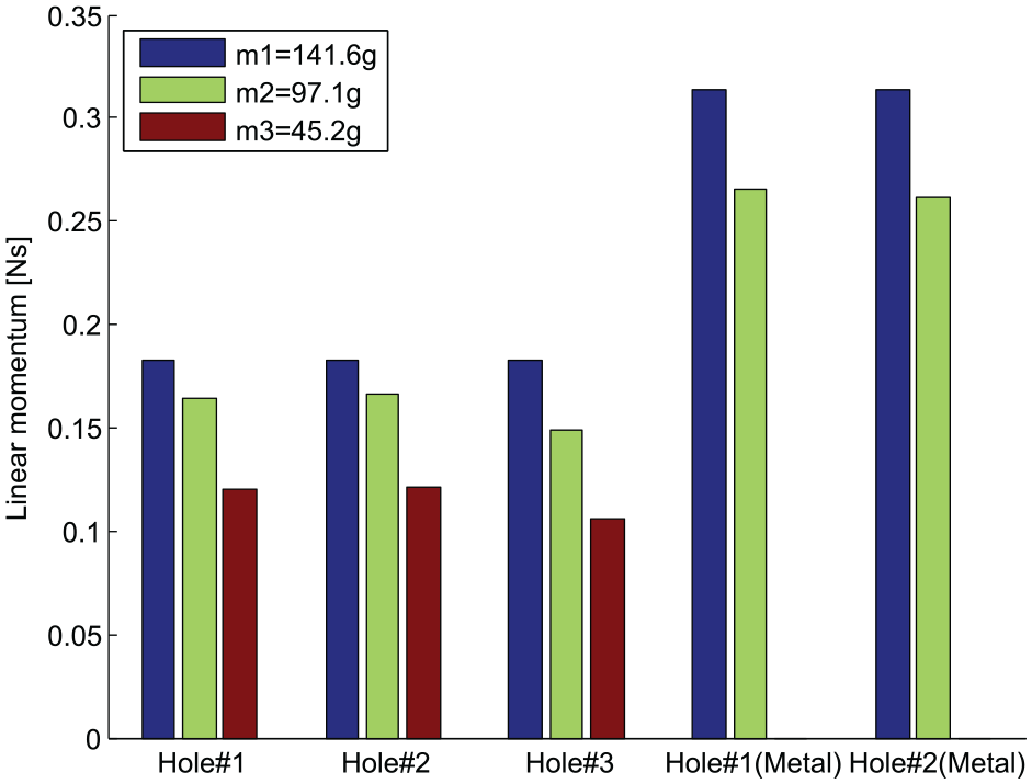
Estimation of the linear momentum involved during a snap-fit insertion for five different assembly items (referred to as holes on the graph) and three different objects (three different masses).
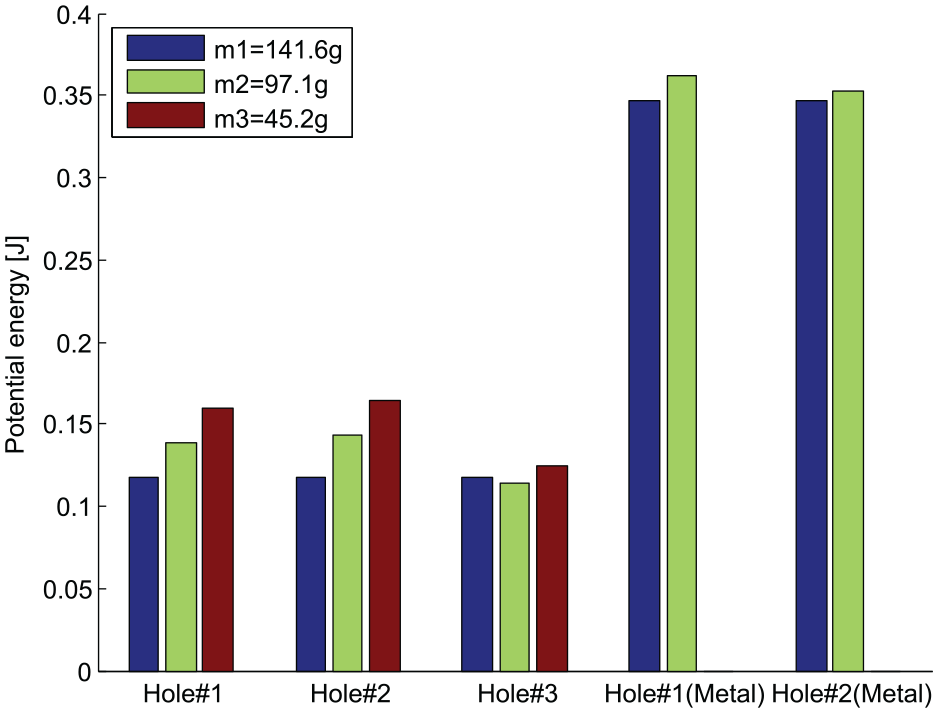
Estimation of the energy involved during a snap-fit insertion for five different assembly items (referred to as holes on the graph) and three different objects (three different masses).
Kinematic principle of the assistive impactor
In industry, the insertion of snap-fit components is commonly done by hand (thumb pressed) or using wooden or rubber hammers. Such tasks induce ergonomic stress on the operators. The objective of this work is to design a tool that can be used to reduce the ergonomic stress, provide better controlled assembly conditions and be eventually transferable to automated work. The ergonomic tool is referred to as an impactor. Similar work on tools to lessen ergonomic stress can be found in Wu et al. 16
Using simple components such as springs, a large impact force can be generated from a reasonably low input torque. This approach is taken here and the design of the tool is based on the impact tests reported in the preceding section. Indeed, it was shown that producing impacts on one of the parts with sufficient energy is a feasible approach to perform the insertion. Moreover, since not all tasks require the same amount of energy, it is useful to be able to adjust the energy of the impact.
Figure 4 shows the main components of the device. The actuated lever revolves around point O and is the input motion of the mechanism. The carriage slides along the X axis. The continuous rotation motion of the lever produces an intermittent translational motion of the carriage whose operation is described in Figure 5.
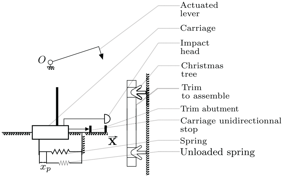
Schematic representation of the impactor device and the parts involved in a snap-fit assembly task.
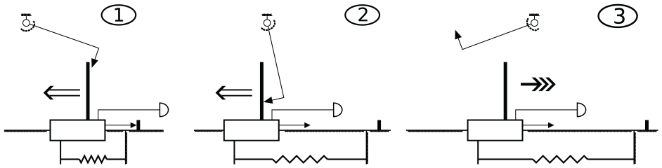
Successive phases of a working cycle of the impactor device.
The operation of the device can be described as follows. During the first step, the lever comes in contact with the carriage. Then, during step 2, this new interaction makes the carriage move backwards and extend the spring. Finally, during step 3, the contact between the carriage and the lever is lost and the energy stored in the spring is released and moves the carriage back to its initial position with a high velocity, thereby generating the impact.
Mechanical analysis of the impactor
The impactor was designed to achieve two main goals, namely, to provide a source of energy close to the task to be performed – and possibly far from the human operator – and to generate forces that are large enough to overcome the static force threshold, that is, the minimum force required to perform the task. Powerful actuators are needed to directly produce the force required for typical insertions. However, such actuators tend to be heavy and bulky, which is an issue in the design of assistive tools, where light and compact solutions must be favoured. Therefore, spring mechanisms are used in this work to produce large forces, possibly at the expense of a longer execution time (time needed to accumulate energy in the spring).
The force profiles of the force required to crank the carriage and the force delivered by the release of the spring are represented in Figure 6.
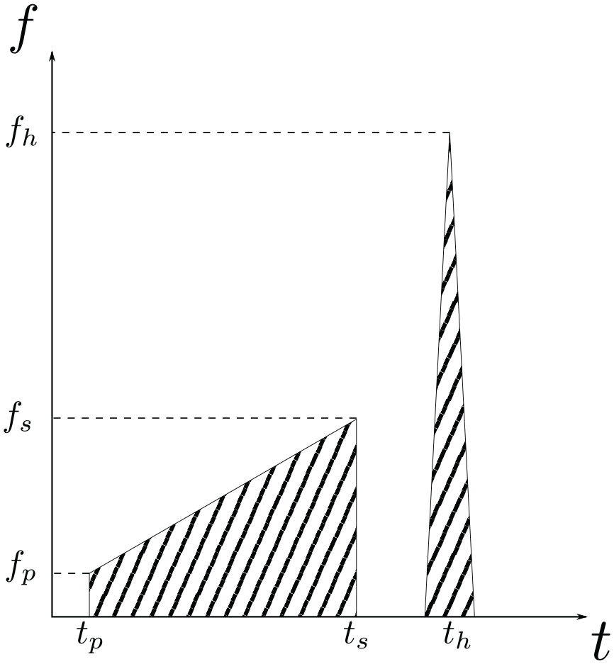
Representation of the forces applied on the carriage over time.
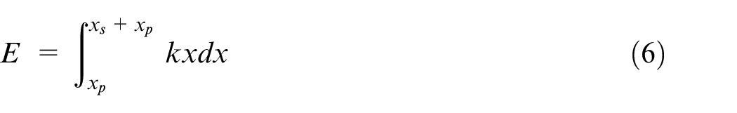
Basically, the system described above stores potential energy in the spring and releases it by letting the spring free to return to its initial state. For the example task described above, the targeted value of the stored energy is
The stiffness of the spring must then be chosen. The preload equivalent length, noted
which yields
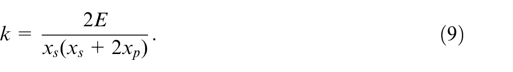
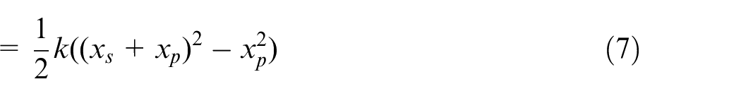
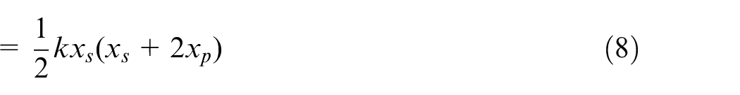
Figure 7 shows the stiffness computed from equation (9) as a function of the required preload, for a stored energy of
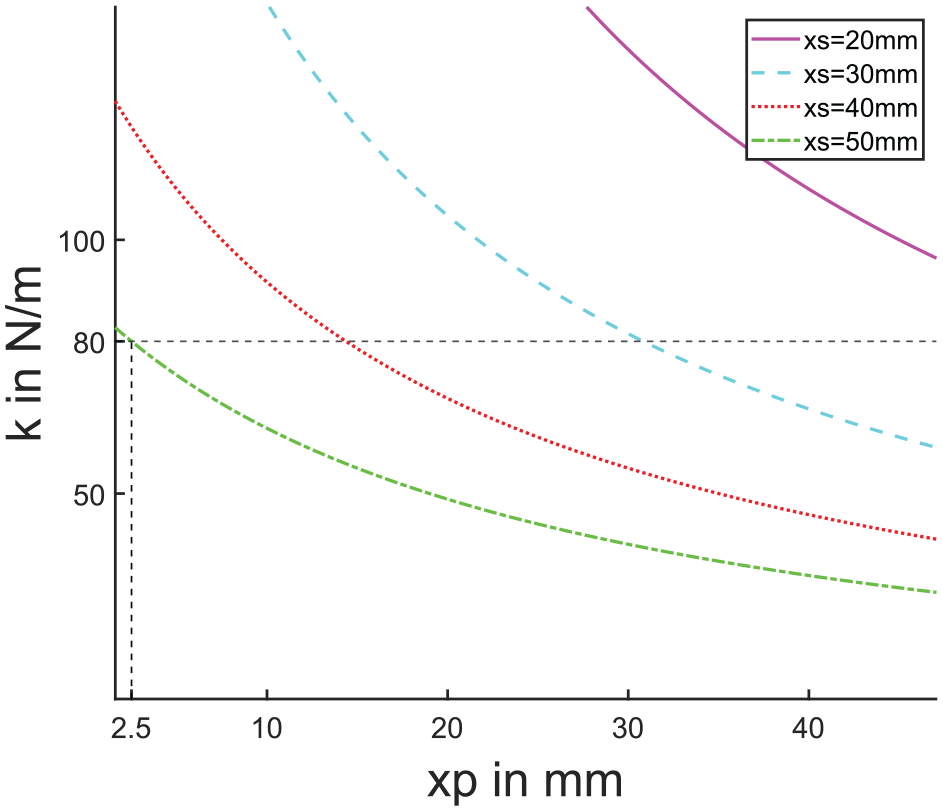
Ideal spring stiffness as a function of the required preload for an energy
In practice, the following approach can be used to choose a spring. First, equation (9) is used to compute the stiffness with

We choose 80 N/m which is the closest lower stiffness available and set the preload to

which corresponds to the dashed lines in Figure 7. In the current design, the preload is set by the choice of the attachment points of the spring. In Figure 8, four attachment points can be seen on the carriage and two on the fixed part.
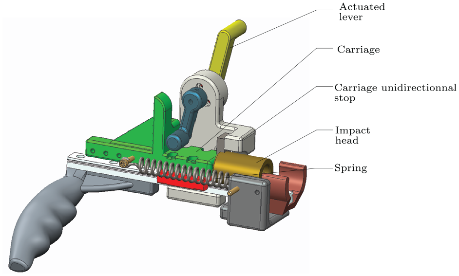
Computer Assisted Design (CAD) model of the impactor with major components identified.
The mechanism described above simulates successive hits similar to a mallet used by a human operator. Therefore, the hit frequency must be considered. The operation of the mechanism involves three different phases discussed above and represented schematically in Figure 5. To be functional, the lever must not interfere with the carriage during its return motion induced by the spring. This represents an upper limit for the impact frequency. Indeed, such an interference happens if the lever is fast enough compared to the time taken by the carriage to produce the impact. The dynamics of the spring-loaded carriage can be represented as
with m the mass of the mobile mass, k the stiffness of the spring, x the position of the carriage with respect to the unloaded position. Solving this equation yields

with
Taking the derivative of equation (15) with respect to time yields an expression for the velocity. Then, solving equation (15) for
As mentioned above, this equation can be used to justify the choice of the stroke. In the example discussed above, we have
which is very close to the maximum value.
Returning to the issue of the operating frequency, based on equation (15), the largest displacement that the carriage can undergo in this phase is from its initial position to when it reaches the mechanical stop. This situation happens when the impactor works free of target and it corresponds to the longest time that this phase can last. From equation (15), one has
With the numerical values given in the example discussed above, one has

As mentioned above, one critical limit of this design is that if the lever rotates too fast for the spring, the carriage as a chance to hit the lever instead of the part to assemble, which would waste the energy stored in the spring, defeating the purpose of the design.
During the time that the carriage makes the impact, the lever must travel around

which limits the maximum working frequency of the input to
where
Prototyping
The CAD model of a prototype of an impactor designed and built as part of this work is shown in Figure 8 and a photograph of the prototype is shown in Figure 9. The prototype can be operated manually or using an actuator. Indeed, the version of the prototype shown in the figures includes a handle for manual operation but the handle can easily be replaced with an actuator. All parts of the prototype are made of 3D-printed ABS plastic except for the spring, the screws and especially a ball bearing carriage and its guiding rail, which yield a low friction motion and determine the overall size of the device.
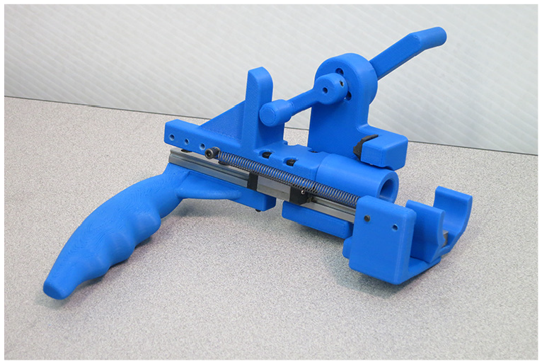
Photograph of the 3D printed impactor.
The device stores the energy for the impact in the extended spring. However, the prototype does also store gravitational potential energy due to the movement of the sliding impact head whose mass is not negligible. Depending on the orientation in which the device is used, the effect of gravity is different. For example, impacting upwards reduces the energy of the impact because a portion of the potential energy stored in the spring is used to move the impact head upwards while impacting downwards increases the impact energy for the opposite reason. Other orientations yield results that are comprised between these two extreme cases. In the prototype, the mass of the impact head (moving mass) is 72 grams, which leads to a maximum energy loss/gain of :


This value is not negligible compared to the
Experimental validation
A video demonstrating the operation of the device is discussed in the video documentation section of the paper.
It should be noted that, when operating the device manually, the impact is barely noticed by the user, because the reaction force is mostly transferred in the axis of the prismatic joint. Therefore, the reaction force displaces the carriage backwards, which is compensated for by the spring.
Press-fit assembly of deformable hoses
The second type of assembly task addressed in this paper is the hose assembly. The flexibility of hoses makes them versatile and convenient in many situations. However, many challenges appear when inserting a hose over a cylindrical shape. The flexibility of the hose can be an issue during the operation because it makes it difficult to apply the loads required for insertion. Therefore, the design of a tool capable of inserting hoses over a cylindrical shape is challenging.
Figure 10 presents a simple model used to estimate the axial force required for insertion in order to help validate the data measured in the next section. In order to obtain a functional hose assembly, the part inserted into the hose – for example, a pipe – must be rigid and larger than the inner diameter of the hose. Therefore, when a part is being inserted in the hose, the hose is deformed and as a result of its elastic material properties, it applies a pressure on the inserted part. It is therefore necessary to generate an input force

The pressure applied by the hose on the object depends mostly on the elastic behaviour of the hose characterized by its Young modulus E. This force can be estimated using the hoop stress, noted
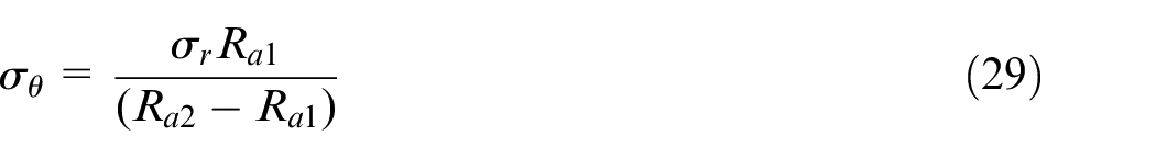
where

where the deformation can be written as
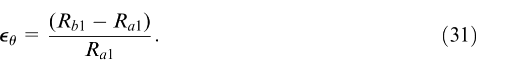
Substituting into the above equations then yields
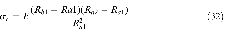
and the axial force resisting to the insertion then becomes

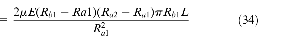
This equation means that the resistive force in the direction of the axis of the hose linearly increases with the length inserted L. To verify this assumption, a test setup composed of a plastic hose, a 3D printed insert and a six-axis force/torque sensor is designed. The setup is identical to the one shown in Figure 19 but without the piezo actuator in the centre. The experiments performed do not aim at verifying the impact of all parameters appearing in equation (34) but rather at verifying the linear behaviour with respect to the inserted length. The results for a straight forward push to insert the hose are shown on the graph appearing on the right-hand side of Figure 20. Considering that the task was performed manually with an approximately constant insertion speed, the linear behaviour observed tends to support the linear behaviour assumption, thereby partially validating the model of equation (34).
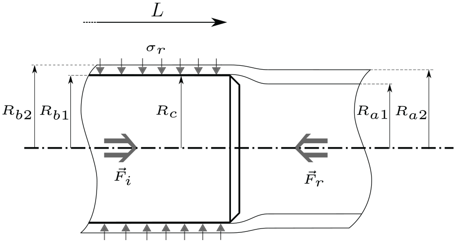
Modelling of the hose assembly for the determination of the required insertion force.
Hoses with an internal diameter of 2 cm and a thickness of 3 mm were used for the experiments reported in this work. The results obtained can be applied to other situations and sizes, as long as the dimensionless deformation
Assembly strategies based on relative motion primitives
The assembly of hoses is generally difficult when attempted with a straight forward motion in the axis of the hose. Although it is the most instinctive method to perform the insertion due to the shape of the parts involved, it becomes obvious, after several trials on real hoses, that alternative methods of insertion seem to reduce the required insertion force. The test setup described above is used to verify this assumption. Six different motion primitives are executed while performing the insertion and a force/torque sensor is used to collect data. The selected motions are referred to as the shaking motion, the twisting motion and the vortex motion, each performed either with low-amplitude or high-amplitude oscillations. Figure 11 illustrates these motions. The shaking motion is a periodic rotational motion around an axis orthogonal to the axis of the cylinder. The twisting motion is a periodic rotation around the axis of the cylinder (hose). The vortex motion is also a periodic rotation around the axis of the cylinder, but in which the hose is given an initial offset angle.
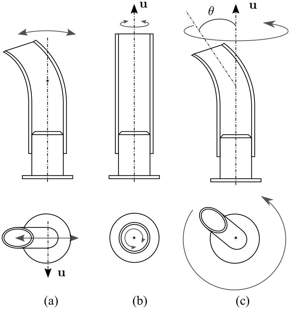
Schematic representation of the relative motion primitives for insertion. For each motion,
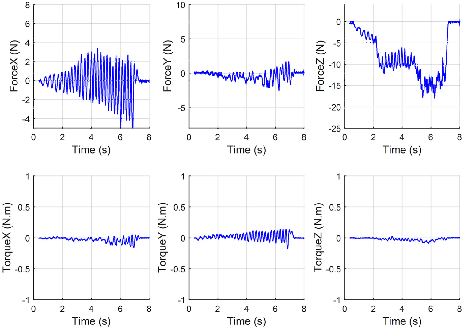
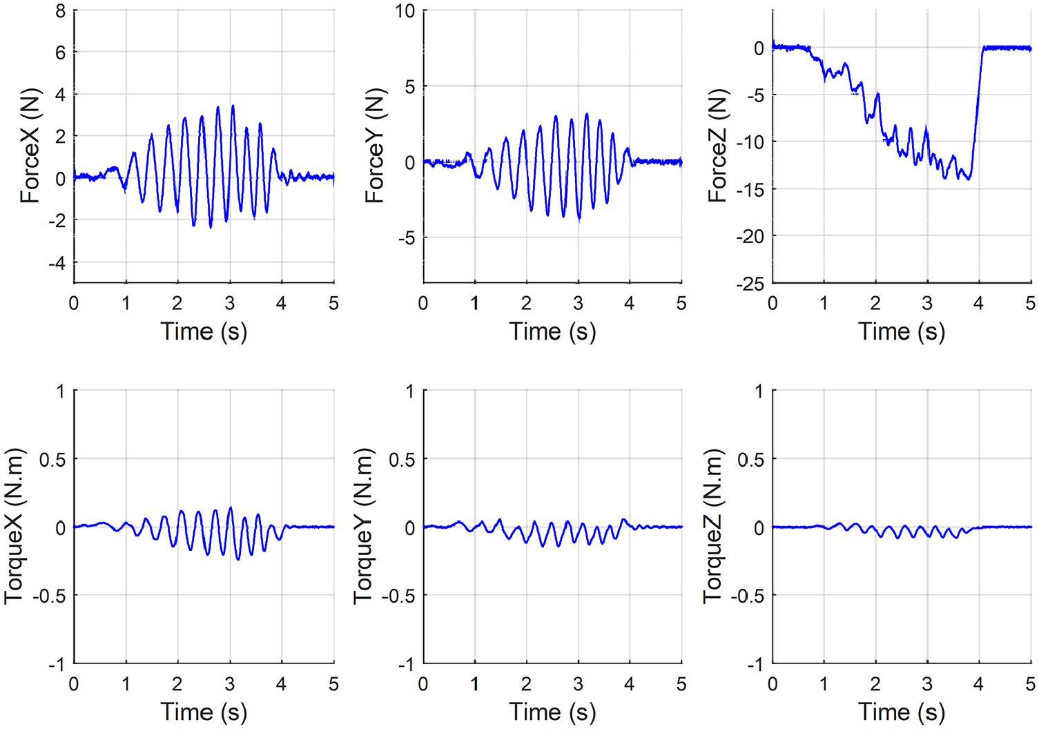
Figure 12 shows the measurements obtained with the 6-axis force/torque sensor during a straight forward insertion. The Z axis corresponds to the axis of the hose and, as expected, the maximum required force is along this axis. For this particular hose and insert, a force of approximately
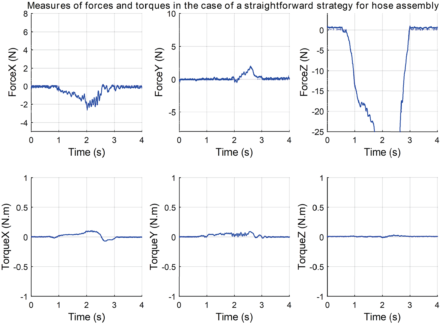
Forces and moments measured by the ATI mini 45 – six-axis force/torque sensor during a straight forward insertion of a hose/insert assembly.
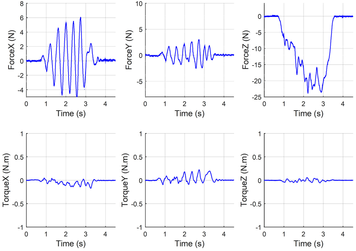
Forces and moments measured by the ATI mini 45 – six-axis force/torque sensor during a high-amplitude shaking motion insertion of a hose/insert assembly.
Forces and moments measured by the ATI mini 45 – six-axis force/torque sensor during a low-amplitude shaking motion insertion of a hose/insert assembly.
Forces and moments measured by the ATI mini 45 – six-axis force/torque sensor during a high-amplitude twisting motion insertion of a hose/insert assembly.
Forces and moments measured by the ATI mini 45 – six-axis force/torque sensor during a low-amplitude twisting motion insertion of a hose/insert assembly.
Forces and moments measured by the ATI mini 45 – six-axis force/torque sensor during a high-amplitude vortex motion insertion of a hose/insert assembly.
Forces and moments measured by the ATI mini 45 – six-axis force/torque sensor during a low-amplitude vortex motion insertion of a hose/insert assembly.
The experimental procedure used for the measurements consists in performing the assembly task using a similar effort in a similar time span. Figure 12 serves as a baseline for the comparison of the results obtained with other insertion strategies.
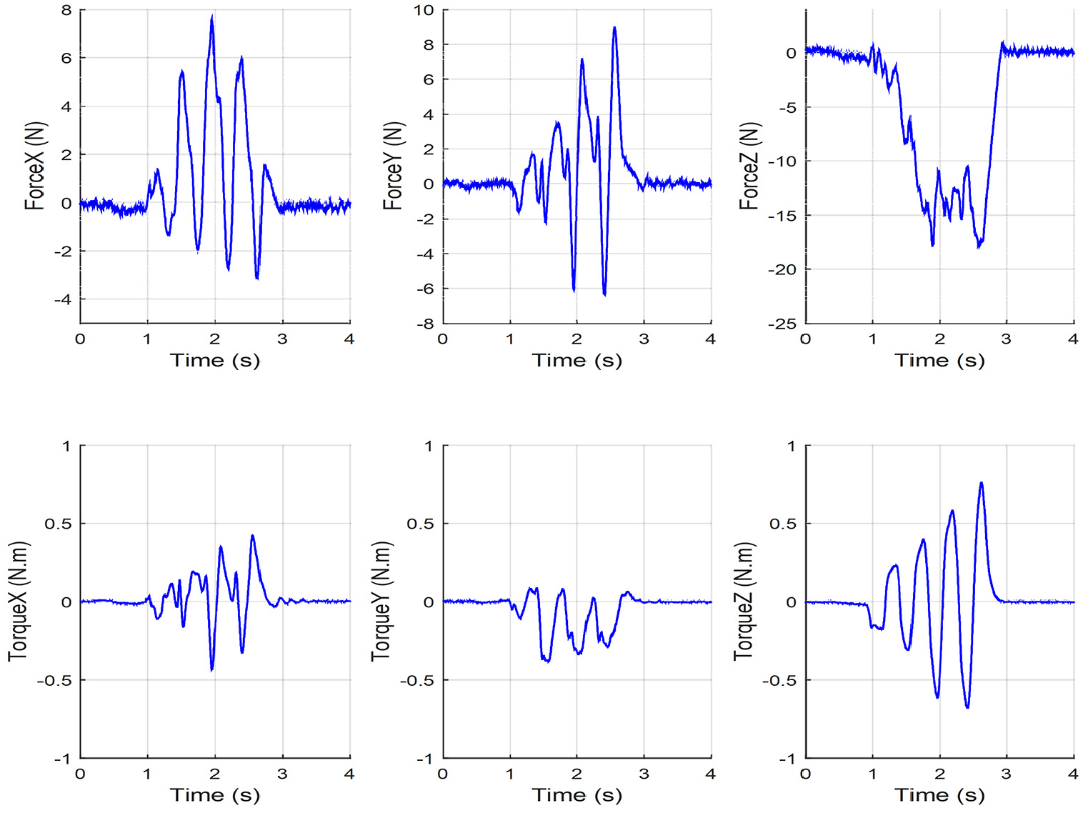
Figure 13 shows the forces and moments measured while performing the insertion with a high-amplitude shaking motion. The shaking motion is a back and forth rotational motion around an axis on the plane orthogonal to the hose’s axis. The video referenced in the last section of the paper shows an example of this motion. The shaking motion generates oscillations of the forces in the X and Y directions with a rather small amplitude. Small oscillations of the torques can also be observed, especially around the X and Y axes. The most noticeable difference when comparing to the reference plots of Figure 12 is that the force along Z (the direction of insertion) is halved. From the user’s perspective, the task feels easier to perform than with the straight forward motion. The shaking motion is a very intuitive solution to ease the manual insertion.
Figure 14 shows the forces and moments measured while performing the insertion with a low-amplitude shaking motion. The scale of the graphs is the same on the plots so as to facilitate comparisons. As it can be observed, the amplitude of the oscillating forces is lowered by the low-amplitude motion. Moreover, the maximum force required in the Z direction is further reduced. However, the motion requires more total energy because the duration of the task is increased. The amplitude of the vibrations is lowered but the frequency is increased and so the increased velocity requires some additional effort from the operator.
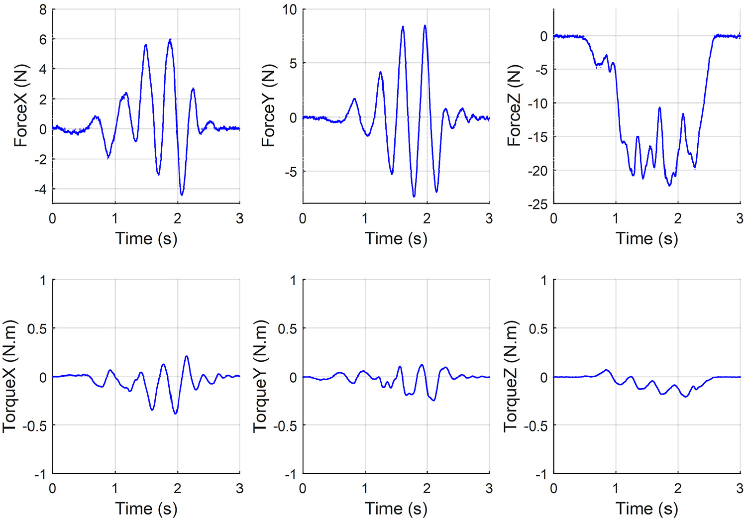
Figure 15 shows the forces and moments measured while performing the insertion with a high-amplitude twisting motion. The twisting motion is a back and forth rotational motion around the axis of the hose. The video referenced in the last section of the paper shows an example of this motion. As expected, it can be observed that the torque around the Z axis is much larger than in the other cases. The force along the Z direction is significantly lowered when compared to the straight forward motion. However, the forces along the X and Y directions as well as the torques around the X and Y directions are higher than in the preceding strategy.
Figure 16 shows the forces and moments measured while performing the insertion with a low-amplitude twisting motion. A recurring pattern is observed when comparing the use of low-amplitude and high-amplitude motions. When high-amplitude motions are used, the magnitude of the insertion force is lower but the effort required by the user is not necessarily reduced. Indeed, since the insertion force is reduced, a larger number of oscillations is required, which also requires additional energy.
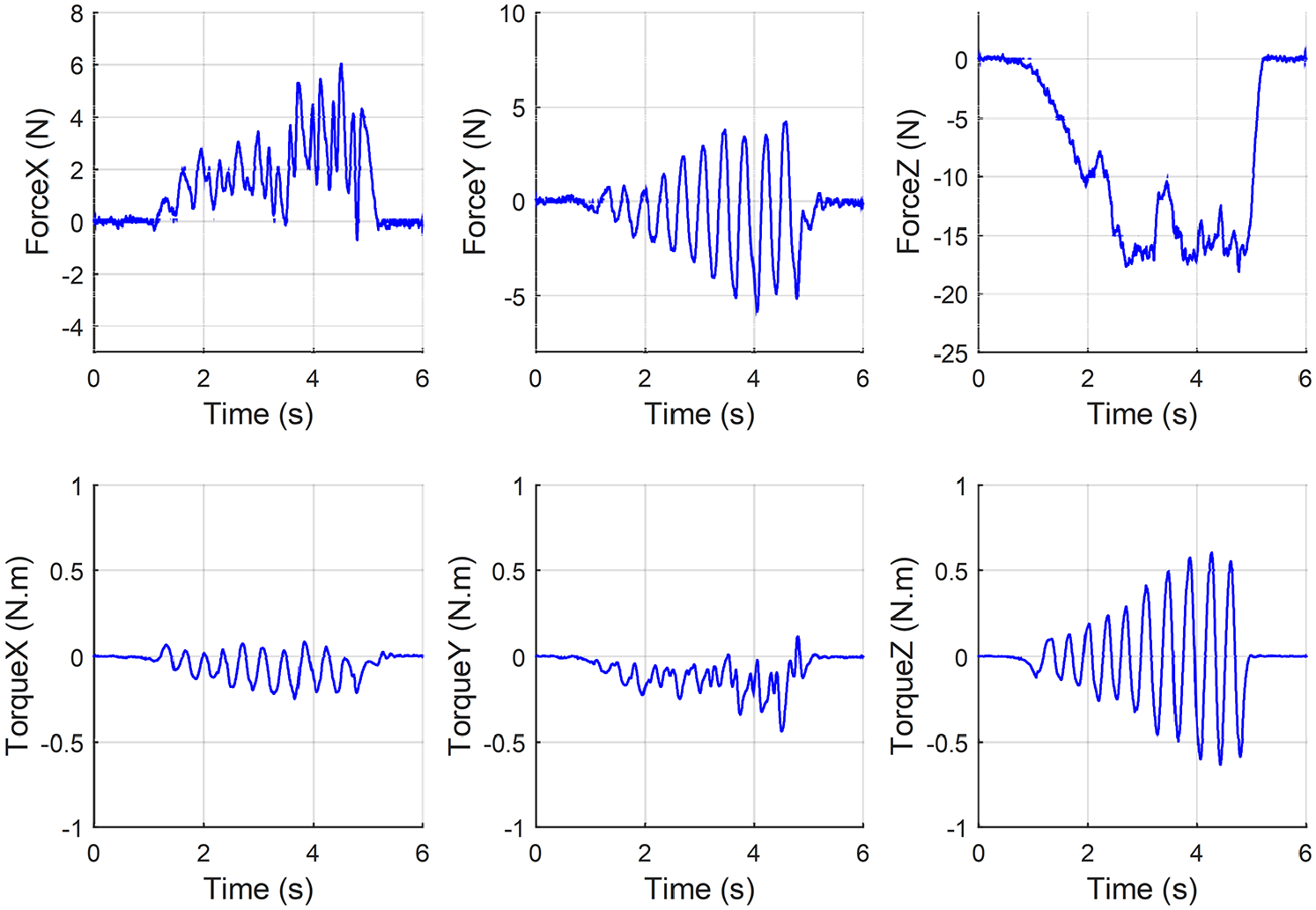
Figure 17 shows the forces and moments measured while performing the insertion with a high-amplitude vortex motion. The vortex motion is a spiral motion around the axis of the insert on which the hose is intended to be mounted. The video referenced in the last section of the paper demonstrates this rather intuitive motion. The results obtained with the vortex motion are similar to those obtained with the twisting motion.
Figure 18 shows the forces and moments measured while performing the insertion with a low-amplitude vortex motion. Based on user feedback and on the force/torque results, this method appears to be the best among those tested. The force along the Z direction is the lowest and other components of force/torque are also low. Nevertheless, although this strategy is the best for a manual assembly, it is not easy to replicate with a mechanical device.
Assembly strategies based on vibrations
The motion primitives described in the preceding section have been shown to ease the insertion. However, it may not be easy to translate this approach into a practical mechanism. Another possible approach consists in using vibrations. The expected behaviour is that vibrations can break the friction between the hose and the insert, thereby greatly reducing the magnitude of the force required for the assembly. This approach is akin to that used in ultrasonic knifes. 17 This assumption has been tested using three vibrating mechanisms mounted rigidly on the insert part. The mechanisms generate vibrations of different amplitude and frequency and have different characteristics such as inertia, volume, cost and ease of use.
The first mechanism is a piezoelectric actuator. The experimental setup used to test this approach is shown in Figure 19. The handle manipulated by the operator is mounted on top of a force/torque sensor that is rigidly attached to the piezoelectric actuator (the bronze coloured box located underneath the force/torque sensor). The part to be inserted in the hose (in blue) is mounted underneath the piezoelectric actuator. The complete assembly is held on top of the hose. The insertion is partially completed on the picture of Figure 19. The experiment consists in manually performing a straight forward insertion with the piezoelectric actuator vibrating and then perform the same insertion with the piezoelectric actuator turned off. The forces measured by the force/torque sensor in each of the two cases are then compared.
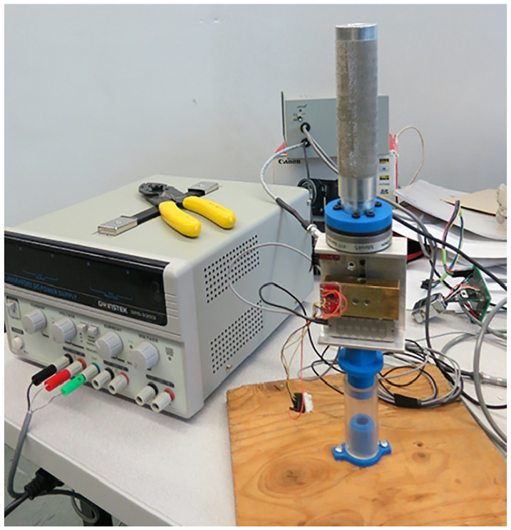
Experimental setup for the hose insertion using vibrations produced by a piezoelectric actuator.
The force measured along the direction of the insertion is shown in Figure 20. The plot on the right-hand side represents the measurement with the piezoelectric actuator off and the plot on the left-hand side represents the measurement with the piezoelectric actuator on. The piezoelectric actuator is rather small and easy to use. However, as observed on the graph, even at maximum power the piezoelectric actuator does not help much. The effect of the piezoelectric actuator can be noted by observing the oscillations around the visible original profile.
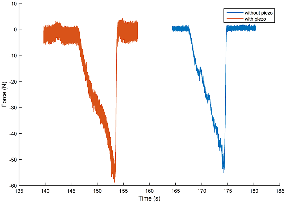
Magnitude of the force in the direction of the insertion with the piezoelectric actuator on (left) and with the piezoelectric actuator off (right).
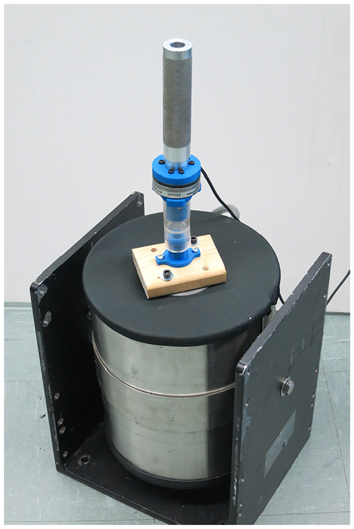
A piezoelectric actuator could be a convenient device to implement as a helping tool for insertion tasks but such actuators lack power. In order to increase the power of the vibrations, a DC motor and an unbalanced mass are used. The motor and mass assembly is fixed on the insert part of the hose/insert assembly. The actuator and unbalanced mass constitute a simple low-cost solution that is not as compact as the piezoelectric actuator and which offers limited control over frequency and amplitude but which provides stronger vibrations. Two different modes were tested: one that produces vibrations in the plane orthogonal to the axis of the hose and one that produces vibrations along the insertion axis. Figure 21 shows the setup in which vibrations are generated along the axis of the hose.
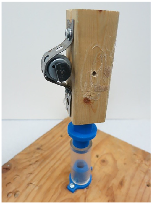
Experimental setup used to generate vibrations with an unbalanced mass and a motor during a hose insertion.
Figure 22 shows the measured force for planar vibrations on the left and the orthogonal vibrations on the right. First, it is noticed that planar vibrations produce significantly more noticeable vibrations than the piezoelectric actuator solution. However, neither the planar vibrations nor the orthogonal ones were successful at significantly easing the insertion of the hose.
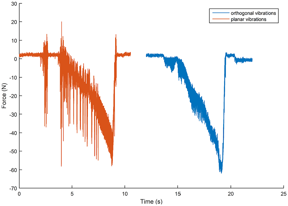
Force along the insertion axis for the motor and mass with the planar mode (left) and with orthogonal mode (right).
The two devices presented above (piezoelectric actuator and unbalanced motor) are relatively compact solutions. However, they lack power and are therefore not very effective. Moreover, the lack of control over the amplitude and frequency of the force applied makes it difficult to find appropriate parameters. Therefore, a third device was tested in order to further investigate the use of vibrations. Although this device does not constitute a practical solution for an insertion task, it is used to investigate the effect of amplitude and frequency on the effectiveness of the insertion. To this end, a laboratory shaker, used for vibration test benches, is employed. Figure 23 shows the experimental setup. The first part of the assembly is fixed on the shaker and the second part is composed of the handle and the force/torque sensor.
Experimental setup used to generate vibrations with a shaker during a hose insertion.
Figure 24 shows the force measured along the insertion axis for a working insertion using the shaker. This type of insertion is demonstrated in the video referenced in the last section of the paper. The parameters that can be controlled are the vibration frequency and the input current, which is directly related to the amplitude. The working parameters used to produce the results are a frequency of 80 Hz and 1 A current. The obtained behaviour is that the insertion requires almost no external force. In fact, the weight of the handle is sufficient to produce the insertion. Not surprisingly, and as observed in Figure 24, the amplitude of the force generated by the shaker exceeds 40 N, which is approximately equal to the maximum force measured to perform the insertion. In other words, the shaker produces a force that is sufficient to break the friction and perform the insertion. Therefore, the force required from the operator is very small. As mentioned above, although the use of a shaker such as the one used here may not be practical, it is nevertheless interesting to note that vibrations could be used for the purpose of facilitating insertions.
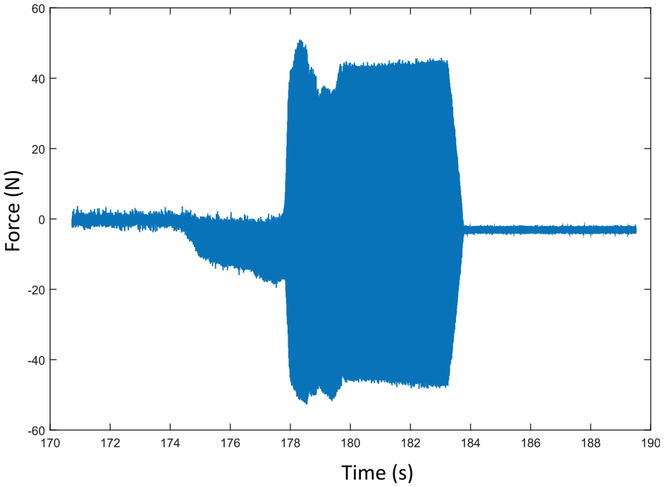
Force along the insertion axis for the insertion with a shaker.
Video documentation
A video accompanies this article. The video can be found at https://youtu.be/M8GztBgY_os . The video illustrates the different measurements presented above. In the first part of the video, the impactor mechanism is used to perform a snap-fit assembly task. The part used for the demonstration is a battery and servos module which is assembled on the door of a vehicle. The module powers and controls electronic devices in the door such as the window or the rearview mirrors. The impactor effectively performs the assembly in one swing, demonstrating the adequate design of the springs for this task. Then, a variant of the impactor is used for a hose assembly task. The impactor applies impacts on a part that fits in the selected plastic hose. The lever of the impactor was modified for this task, that is, several levers were added on the rotating part so that the frequency of the impacts is increased, at the cost of a reduced stroke for the spring and therefore less energy per impact. The intent was to get closer to a vibrating behaviour, assumed more effective than the strong less frequent impacts. The result was not conclusive and led to the study of vibrations using the shaker. The next segment of the video shows the acquisition of the data presented above. The motion strategy measurements are then demonstrated, together with the motions described in the text. Finally, the tests performed with the shaker are demonstrated.
Conclusion
This article studied snap-fit and press-fit assembly tasks, with the aim of developing effective tools that can help operators and reduce ergonomic stress. The design of a reliable and easy to use tool for the snap-fit assembly was presented and a prototype was built and tested. Then, the experimental investigation of press-fit (hose assembly) tasks was presented and different insertion strategies were explored. Finally, the use of vibrations as a means of facilitating insertions was investigated. It was shown that vibrations can indeed facilitate insertions, but their use in practical applications remains challenging. The results presented in this paper have the potential to yield the development of novel effective tools and strategies for snap-fit and press-fit assembly.
Footnotes
Acknowledgements
The help of Simon Foucault in the design of the experimental test rigs and mechanisms presented in this paper is also gratefully acknowledged.
Declaration of conflicting interests
The author(s) declared no potential conflicts of interest with respect to the research, authorship, and/or publication of this article.
Funding
The author(s) disclosed receipt of the following financial support for the research, authorship, and/or publication of this article: The authors would like to acknowledge the financial support of the Natural Sciences and Engineering Research Council of Canada (NSERC) and of General Motors of Canada.
Research ethics
This research was conducted in accordance with all research ethics guidelines of the organisations and funding agencies involved.