
Abstract
Tolerance analysis represents the best way to solve assembly problems in order to improve the quality and to reduce the costs. It is a critical step to design and to build a product such as an aircraft and its importance is grown up in the past years. This work presents a method for the tolerance analysis of an assembly involving free-form surfaces with large dimensions. The assembly is a tail beam, a structural component of an aircraft that is constituted by five parts of large dimensions. The influence of the tolerances applied to the five components of the tail beam on the value of the gap at the interfaces among the parts has been deeply investigated. A set of control points have been distributed on the free-form surfaces of the tail beam; its number and its distribution have been opportunely designed. Moreover, the influence of the tolerances on the other requirements of the tail beam connected with the motion drive has been studied. Tolerance analysis has involved the choice of the assembly tools and sequence too. The assembly jigs are mated with the assembly components through pins that are inserted into tooling holes located on the assembly components. The fit conditions have been modeled and the tolerances of the tooling hole have been opportunely chosen. Each tolerance of the tail beam components has been modeled by means of a probability density function. Monte Carlo approach has been used to obtain the statistical distribution of the assembly requirements, once dimensions and geometry of the tail beam components have been perturbed inside the tolerance ranges. Monte Carlo simulation has been carried out by a well-known computer-aided tolerance software, eM-Tolmate of UGS®.
Introduction
To design and to manufacture high-quality products with lower costs in mechanical field, tolerance analysis is an essential step. To reduce the number of rejects or the amount of rework required on components and, therefore, to limit the manufacturing costs, an appropriate allocation of the tolerances among the assembly components can increase the probability of fit. Moreover, the tolerance analysis guarantees that the product will work rightly, since it evaluates the influence of tolerances assigned to the assembly components on functional clearances or fits of assembly.1,2
In the aeronautic field, the tolerance analysis is a very critical step of the design stage, since the innovative materials and the complexity of the shapes of the structures, to which high performances are required, need advanced design techniques and assembly technologies.3,4 Many components are in composite material and involve complex structures that are joined together by lines of adhesive. Composite material involves unsolved production and assembly problems, even if it allows to obtain light components with an increase in the performances of the aircrafts. Tolerance analysis involves the choice of the assembly jigs and the sequence that allows to satisfy the designed geometric and dimensional tolerances of the final product. It is a fundamental tool to predict whether the production and the assembly processes are able to guarantee the respect of the standards required.
Many well-known approaches exist in the literature for tolerance analysis.5,6 The analytical methods proposed by the literature are not easy to apply, especially for complex aerospace assemblies, since they were created to deal with elementary features, such as planes, holes and pins. Today, computer-aided tolerance (CAT) software is readily available, but even if these tools provide good results, they have not been widely used.7–10 Commercial CATs are not completely true to the geometric dimensioning and tolerancing (GD&T) standards and need improvement after a better mathematical understanding of the geometric variations.
More recent works of the literature aim to apply the methods of the tolerance analysis to more complex systems, such as systems in motion, 11 to take into account manufacturing deviations, such as models of manufactured parts, 12 or critical operating conditions, such as changes in temperature, pressure or speed. 13
The aim of this work is to present a method for the tolerance analysis of a large assembly involving free-form surfaces based on dimensional and geometric tolerances. There has been much effort in this work to deal with dimensional and geometric tolerances applied to free-form surfaces. The assembly is a tail beam of an aircraft that is actually made in aluminum alloy. The idea of this work is to study the possibility to manufacture the whole tail in composite material by decreasing the assembly weight. Therefore, the design of the new composite tail beam has been deeply investigated by the authors in order to verify whether it satisfies both the assembly constraints and the functional requirements. The influence of the tolerances applied to the five components of the tail beam on the value of the gap at the interfaces between each couple of parts has been deeply investigated by means of the proposed method. Moreover, the influence of the tolerances on the motion drive requirements of the tail beam has also been studied. The free-form surfaces of the components have been schematically represented by a set of control points, whose number and distribution have been opportunely designed. The assembly sequence has been designed according to the functional requirements. The equipment used to assemble the tail’s beam components has been designed and considered in nominal conditions. The manufacturing process is assumed to produce parts whose dimensions and geometry are inside the tolerance ranges, since the focus of this work is on the tail beam design. A Gaussian probability density function has been used to characterize each tolerance of the tail beam components. Monte Carlo simulation has allowed one to perturb dimensions and geometry of the tail beam components inside the tolerance ranges in order to give the statistical distributions of the assembly requirements. Monte Carlo simulation has been carried out by a well-known CAT software, eM-Tolmate of UGS®.
This article is organized as follows: in section “Case study,” the case study is presented. In section “Tolerance analysis aims,” the assembly sequence and the assembly jigs are deeply described. In section “Proposed method,” the proposed method to build the stack-up functions is described, while in section “Results and discussion,” the stack-up functions are solved and the obtained results are deeply discussed. Finally, in section “Redesign of rib’s jig,” the assembly jigs are redesigned on the basis of the results of section “Results and discussion.”
Case study
The case study is represented by the tail beam of an aircraft shown in Figure 1(a). It is composed of five parts: a spar, a rib, two skins and a bulkhead (see Figure 1(b)). Skins constitute the airfoil. Spar, rib and bulkhead are together the bearing structure of the assembly. The spar allows the driving of the tail rotor through a gearbox of 90° lodged on it, the rib sustains the transmission tree of the motion to the tail rotor and the bulkhead constitutes the interface between the tail beam and the aircraft. The orientations among them represent fundamental references for the assembly.
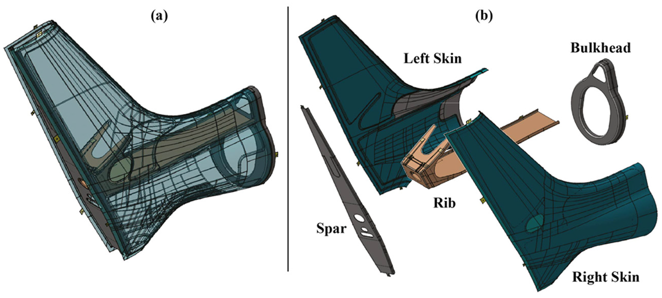
(a) Tail beam and (b) tail beam’s components.
The components of the tail beam are made up of composite material with carbon fibers and epoxy matrix in order to obtain a strength-to-weight ratio higher than the metallic material’s. The five parts of the tail beam are connected by adhesive. Adhesive thickness between the faced parts to connect should be as constant as possible in order to obtain an efficient structural connection and to avoid local compressions at the interface of faced parts due to strong reduction in thickness. The influence of the tolerances applied to the five components of the tail beam on the value of the gap at the interfaces between skin and rib, skin and spar, rib and spar, rib and bulkhead, and bulkhead and skin has been deeply investigated, as described in the following. The influence of the tolerances of the five components on the motion drive performances of the tail beam has also been verified through two variables: the parallelism between the adhesive’s planes of rib and spar and the perpendicularity between the axis of the rib and the plane of the bulkhead as deeply described in the following. Finally, the encumbrance of the whole tail beam needs to be controlled by means of the offset parameters.
The dimensional and geometric tolerances applied to the five components of the tail beam are as follows: a dimensional tolerance on the thickness of the surfaces that have to be connected by adhesive of about 10% of the nominal value, a parallelism tolerance of 0.10 mm on the surfaces that mate with the assembly jigs, nominal dimensions of the diameter of the holes used to couple each component with the corresponding jig and a position tolerance of 0.12 mm applied to the holes used to couple each component with the corresponding jig. The dimensioned drawings may not be published for reserved reasons.
Tolerance analysis aims
Thickness and spread of the adhesive’s gap
The five parts of the tail beam are joined together by lines of adhesive. To have an efficient structural connection and to avoid local compressions between two faced parts, the constancy of the adhesive thickness should be guaranteed and the adhesive gap has to be higher than a limit value.
This work has estimated the probability that interference conditions and excessive gap variations occur at the interfaces between skin and rib, between spar and rib, between spar and skin and between bulkhead and skin. In particular, interference occurs if the distance between the two faced components is lower than the minimum thickness of the adhesive net (S1min, S2min = 0.08 mm); the trend of the gap between two faced components is considered non-uniform if the difference between the maximum and the minimum values of the gap is higher than a reference value (Δs = 0.3 mm), as shown in Figure 2.
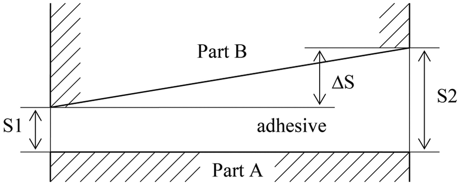
Thickness and spread of adhesive gap.
The trend of the gap among tail beam’s components, which has to be filled with adhesive, has been evaluated in this work. Eleven gaps have been considered: three between spar and rib; two between left skin, and spar and rib, respectively; two between right skin, and spar and rib, respectively; two between skins; and two between bulkhead and skins. The presence of interferences and the uniformity of each gap have been estimated for the 11 gaps, as previously described.
The trend of the gap is influenced by the degrees of freedom each component of the tail beam has with regard to the other components of the assembly due to the applied tolerances or to the assembly sequence. The assembly sequence has been designed; the details are reported in section “Assembly sequence.”
Skin may vary its thickness due to the applied dimensional tolerance toward the rib, the spar and the bulkhead, where the mating between skin and the related jig causes thickness variation to decrease the gap between the skin and rib, skin and spar, and skin and bulkhead. It may rotate with regard to its fixture equipment, due to the dimensional and positional tolerances applied to the holes that couple with jig’s pins. It may change its orientation due to the parallelism tolerance with the jig. Rib may vary its thickness due to the applied dimensional tolerance toward the spar and the skins, where the mating between rib and the related jig causes thickness variation to decrease the gap between rib and spar, and rib and skin. Rib may rotate with regard to its fixture equipment, due to the dimensional and positional tolerances applied to the holes that couple with jig’s pins. Rib may change its orientation due to the parallelism tolerance with the jig. Spar may vary its thickness due to the applied dimensional tolerance toward the rib and the skins, where the mating between spar and the related jig causes thickness variation to decrease the gap between spar and rib and spar and skins. Spar may rotate with regard to its fixture equipment, due to the dimensional and positional tolerances applied to the holes that couple with jig’s pins. Spar may change its orientation due to the parallelism tolerance with the jig. Bulkhead may vary its thickness due to the applied dimensional tolerance toward the skins, where the mating between bulkhead and the related jig causes thickness variation to decrease the gap between bulkhead and skins. Bulkhead may rotate with regard to its fixture equipment, due to the dimensional and positional tolerances applied to the holes that couple with jig’s pins. Bulkhead may change its orientation due to the parallelism tolerance with the jig.
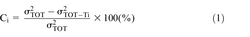
The 11 trends of adhesive gap depend on the previously defined tolerances and on the assembly constraints that are deeply described in the following. The applied tolerances have been considered distributed as a Gaussian probability density function. Monte Carlo simulation has been adopted to define the probability distribution connected to the 11 trends of adhesive gaps. The number of runs of simulation has been fixed at 50,000, once many tests were carried out, since this value guarantees a reliable estimation of the mean and the standard deviation of the probability distribution characterizing each gap. Finally, a sensitivity analysis has been carried out in order to identify the tolerances mainly affecting each gap trend. The percentage weight of each tolerance has been calculated by evaluating the variance of a gap trend σTOT, when all the previously introduced tolerances are applied to the tail beam’s components, and the variance of the same gap trend σTOT-Ti, once ith tolerance is not applied to the tail beam’s components
Drive motion requirements
Tail beam has to guarantee to bring the torque from the main rotor axis to the rotor axis. The second assembly requirement is the motion drive performances of the tail beam that have been geometrically evaluated by means of two geometrical parameters. The first is the parallelism between the adhesive planes of rib and spar, as shown in Figure 3(a). Its range should be ±0.05° in order to guarantee a right positioning and orientation of the mechanical parts that have to be allocated in the tail beam, such as auxiliary rotor, gear units and joint transmissions. The second geometrical parameter is the perpendicularity between the rib’s axis and the bulkhead’s plane, as shown in Figure 3(b). It should range between ±0.02° in order to guarantee a right positioning and orientation of the tail beam with respect to the fuselage of the aircraft.
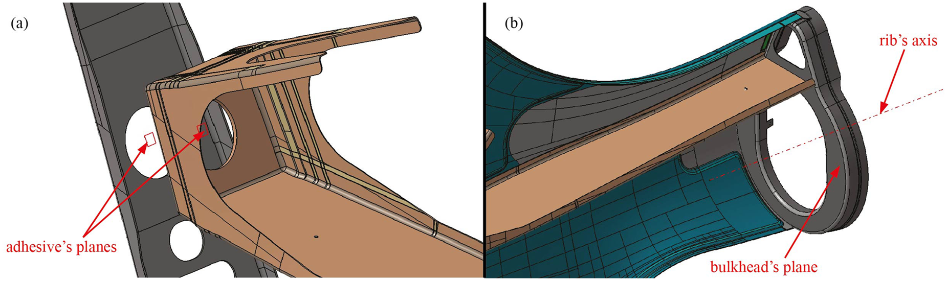
(a) Parallelism between adhesive’s planes of rib and spar and (b) perpendicularity between rib’s axis and bulkhead’s plane.
Finally, the encumbrance of the whole tail beam has been controlled by means of the offset parameters. To guarantee that the boundary surfaces of the skins are joined together without any discontinuities and deviations of form on the fuselage of the aircraft, the offset control points of the skins have to be included inside an offset zone of ±0.4 mm with regard to the nominal geometry, once the skin is assembled with the other components of the tail beam.
Assembly sequence
The assembly sequence of the tail beam is constituted by five steps, as shown in Figure 4. The first step involves the couple of each component on its jig to constitute a subassembly. During the second step, the rib’s jig is mated with the spar’s jig; the gap between the two faced planes of rib and spar is filled with adhesive that is fixed at 130°. During the third step, the left skin’s jig is mated with the spar’s jig and the left skin is connected to the rib. The fixture equipment of the rib is removed and the left skin’s jig is mated with the spar’s jig. The gaps among skin, spar and rib are filled with adhesive that is fixed at 130°. Then, the right skin is assembled in the same way as the left skin, and finally the bulkhead’s jig is mated with the rib’s jig and the bulkhead is connected to the rib by means of metallic insert and to the skins by adhesive.
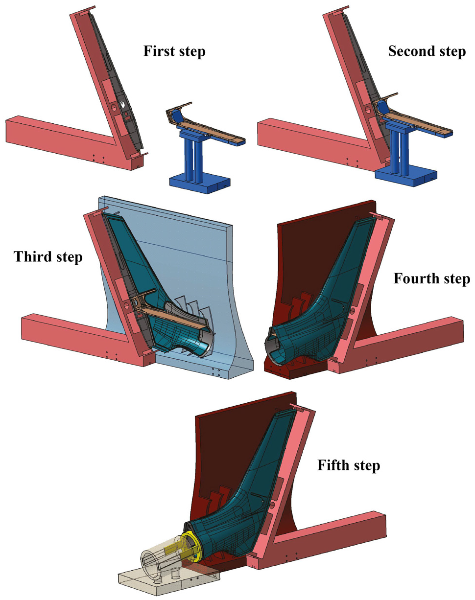
Assembly sequence of the tail beam.
To orient and to fix each component on its jig, a tooling hole (TH) system has been adopted. It involves a planar contact and two pin–hole clearance fit between the part and its assembly jig. Once positioned on the corresponding assembly jig, the part is fixed by means of clamps. In this study, the assembly jigs and their pins are considered nominal, while the THs have a dimensional and a position tolerance. 14 The fit among pins and THs has to be with clearance in order to be assembled. In a previous work, 15 the dimensional and position tolerance to assign at the TH have been studied and optimized to guarantee the respect of the constraints required on the adhesive lines of the tail beam. In the following, these conclusions will be directly applied; so for the THs, position tolerances of ϕ = 0.12 mm are used that are related to an accurate production process of them, and a nominal diameter since calibrated bushes are used (Figure 5).
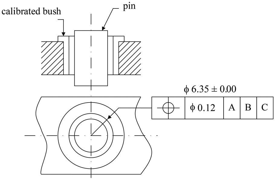
TH’s tolerances.
Assembly jigs
The assembly jigs should have a plane and two pins in order to locate and fix the coupling component. The position of the THs has an important role in order to limit the flag waving effect of the component as regards its assembly jig, since a small change in THs’ position causes a great variation in the location and the orientation of the part on the corresponding jig due to the big dimensions of the parts. Therefore, the distance among the THs must be as bigger as the dimensions of the part increases, but this condition is difficult to achieve in some practical cases. Another important consideration is that it is preferred to position the THs out of the part shape, on appendixes that will be trimmed once the part is assembled, in order to have lower production costs. Through these considerations, the assembly jigs have been designed for each part. The designed jigs are shown in Figure 6. In this study, the assembly jig has nominal dimensions and shape, so the positioning between them is always ideal.
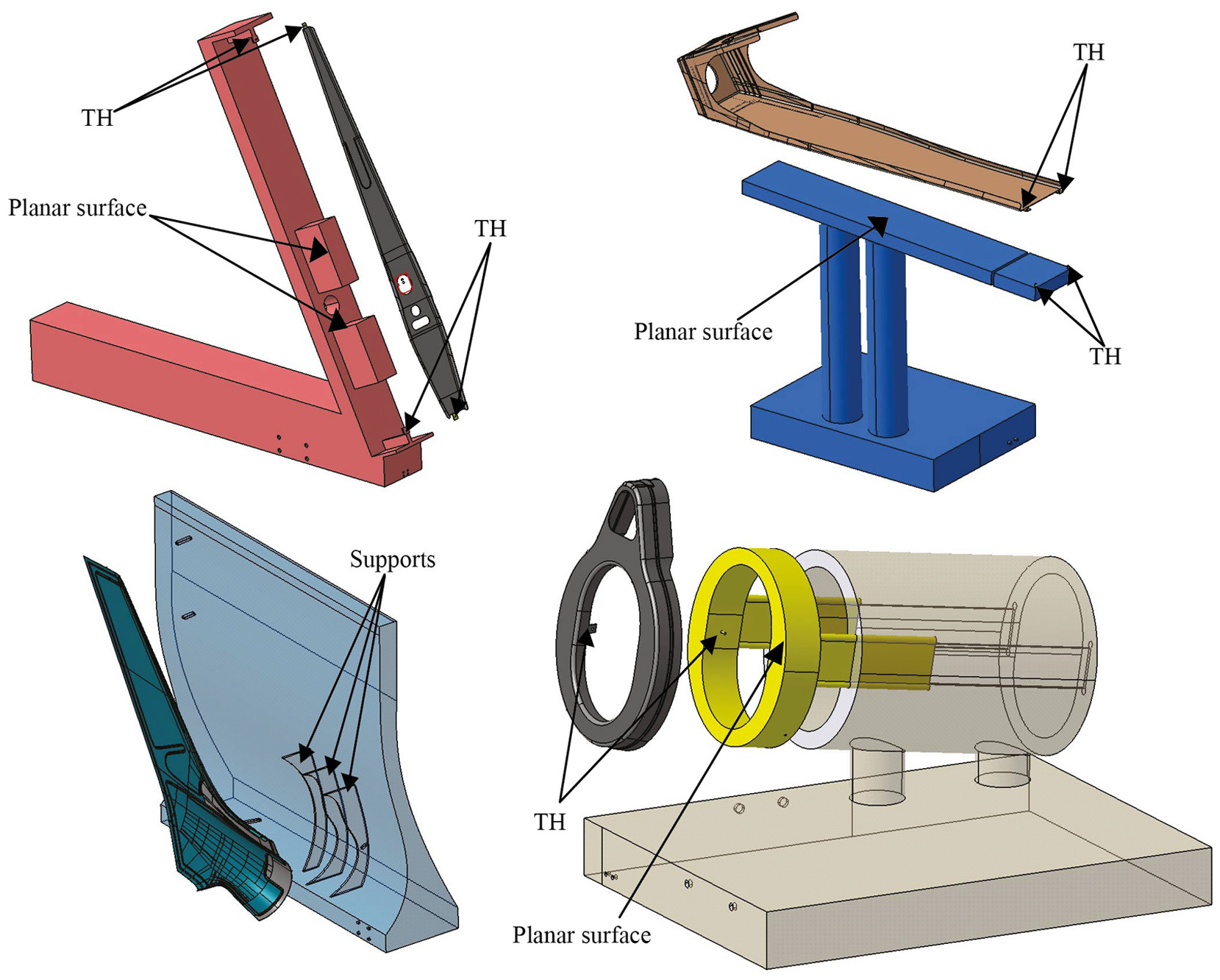
Assembly jigs.
Proposed method
Thickness and spread of the adhesive gaps
In order to evaluate the trend of each gap at the interface between two faced free-form surfaces of tail beam, some considerations are needed. CAT software performs a surface-to-surface distance by calculating the distance between the barycenters of the two faced surfaces. The aim of the adhesive gap tolerance analysis is to obtain a distance map along the whole gap between two faced surfaces. CAT software’s limits can be subdued by building control points on each surface. The principle to select the measurement points was to keep constant the curvature of the surface between two consecutive points. If we consider spar and skin gap, for example, a pattern of 12 points can be built on spar surface as shown in Figure 7(a); a normal vector is associated with each point. The spar’s pattern of normal vectors intersects the surfaces of skin by defining another pattern of points. To evaluate the distribution of the minimum distance between spar and skin, the distance of each point of the spar from the skin surface needs to be calculated. CAT software calculates a three-dimensional (3D) point-to-point distance that does not correspond to the minimum distance. In nominal configuration, the points of the skin and the rib lie on the same normal direction and, therefore, the minimum distance is a point-to-point distance between the two identified patterns. When tolerances are applied to the part, the spar changes its orientation with regard to the skin. The minimum distance between the two patterns of points belonging to spar and skin has been calculated by projecting the point-to-point distance along the direction perpendicular to the surfaces of the spar and the skin that are faced in nominal conditions. The obtained map of distances is very near the minimum distances, as demonstrated in Polini et al. 16 The same considerations have been applied to choose the pattern of control points belonging to the couples of faced surfaces along spar and rib, rib and skin and bulkhead and skin. The results are shown in Figure 7.
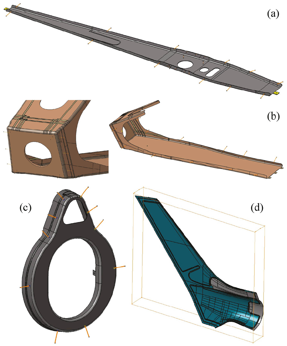
Control points on (a) spar, (b) rib, (c) bulkhead and (d) left skin.
Drive motion requirements
The angle between the two faced surfaces of spar and rib has been estimated. The rotations around the y- and z-axes, which are parallel to the rib face, have been measured since they are responsible for the change in the relative orientation, while the rotation round the z-axis does not affect the parallelism requirement, as shown in Figure 3(a). The angle between the rib’s axis and the bulkhead’s plane has been estimated by evaluating the rotations around the y- and z-axes, which are parallel to the bulkhead’s plane, while the rotation around the z-axis does not affect the perpendicular requirement, as shown in Figure 3(b). Finally, the offset of the tail beam has been investigated by a pattern of eight points: four of them (LFT Back Up, LFT Back Down, LFT Forward Up and LFT Forward Down) are fixed on the left skin and four (RGT Back Up, RGT Back Down, RGT Forward Up and RGT Forward Down) are fixed on the right one (see Figure 8). The displacement of each point along the three Cartesian axes has been measured.
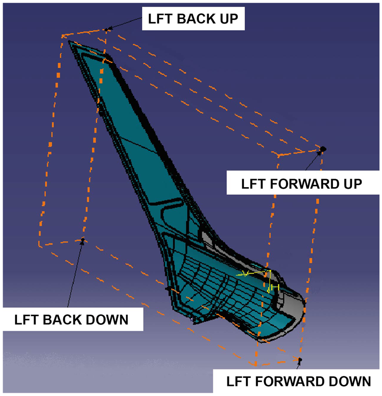
Control points of left skin offset.
Results and discussion
The tolerance analysis has been carried out by means of eM-Tolmate, that is, a commercial software based on a variational tolerance model.11–13
Monte Carlo approach has been adopted with 50,000 runs of simulation and a Gaussian probability density function for each applied tolerances. A sensitivity analysis has been carried out too.
Thickness and spread of the adhesive’s gap
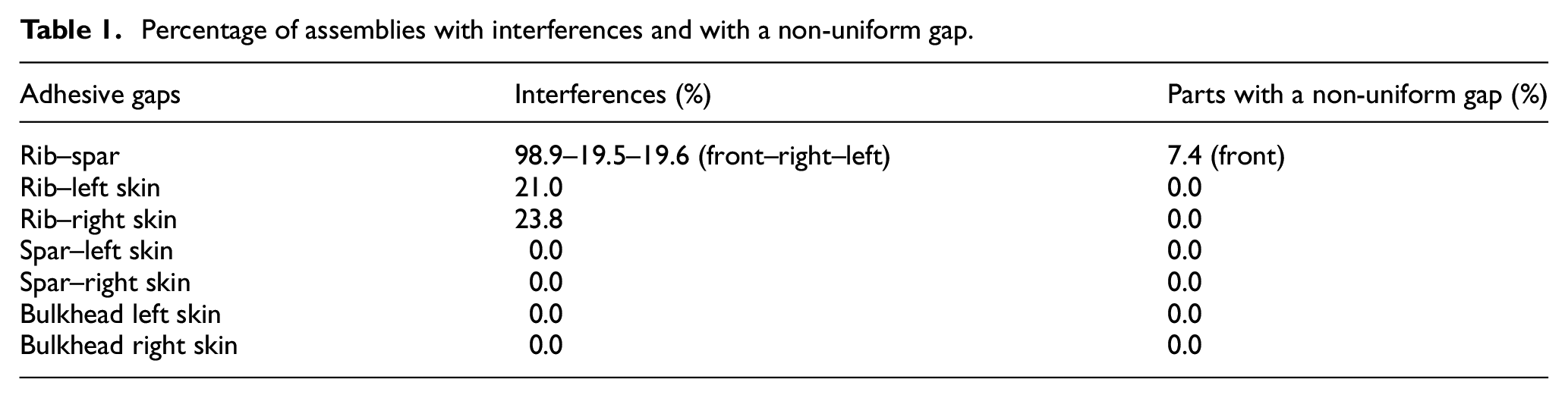
The results show that the distribution of the distance of any couple of considered faced points looks like a Gaussian, whose parameters (mean and standard deviation) have been estimated. The more probable values of the distance have been represented by the mean and the two percentiles (±3σ) that include 99.73% of the obtained Gaussian distribution for each couple of points, as shown in Figures 9–12. The percentage of assemblies with interferences has been estimated by calculating the area under the obtained Gaussian distribution below the admitted limit of 0.08 mm and above the limit of 0.60 mm. The results are reported in Table 1. Finally, to estimate the uniformity of the gap between two faced surfaces, the distribution of the difference (Δs) of the distances of the two extreme couples of points belonging to the two faced surfaces has been estimated. The percentage of parts whose Δs overcomes the fixed maximum value (0.30 mm) has been evaluated and shown in “Parts with a non-uniform gap” column in Table 1.
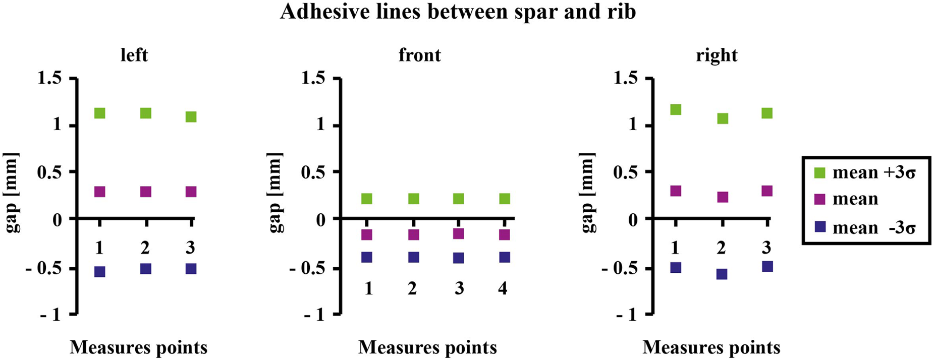
Distance of all the couples of points of spar–rib gap.
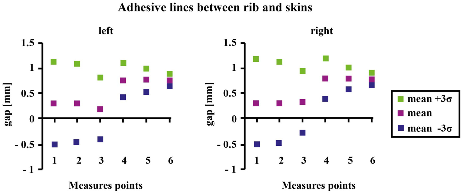
Distance of all the couples of points of rib–skin gap.
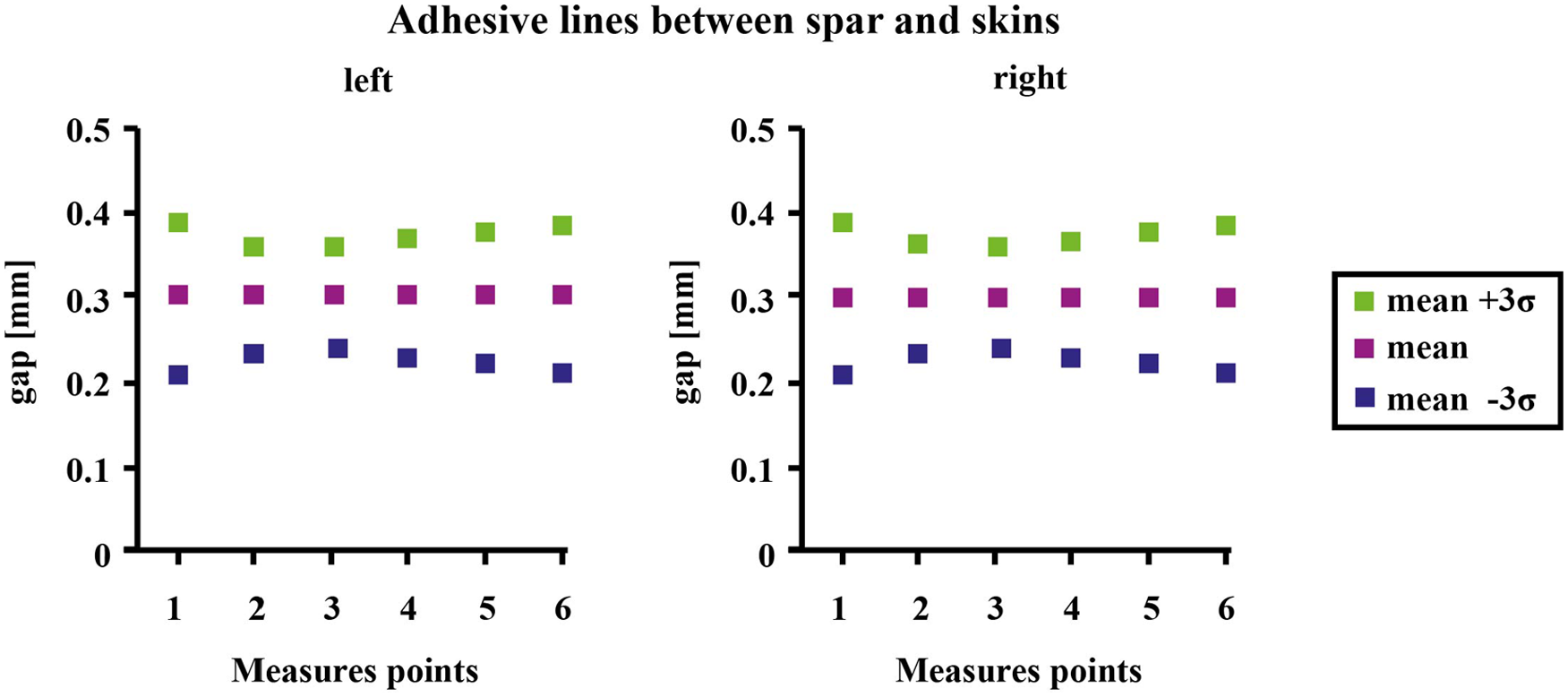
Distance of all the couples of points of spar–skin gap.
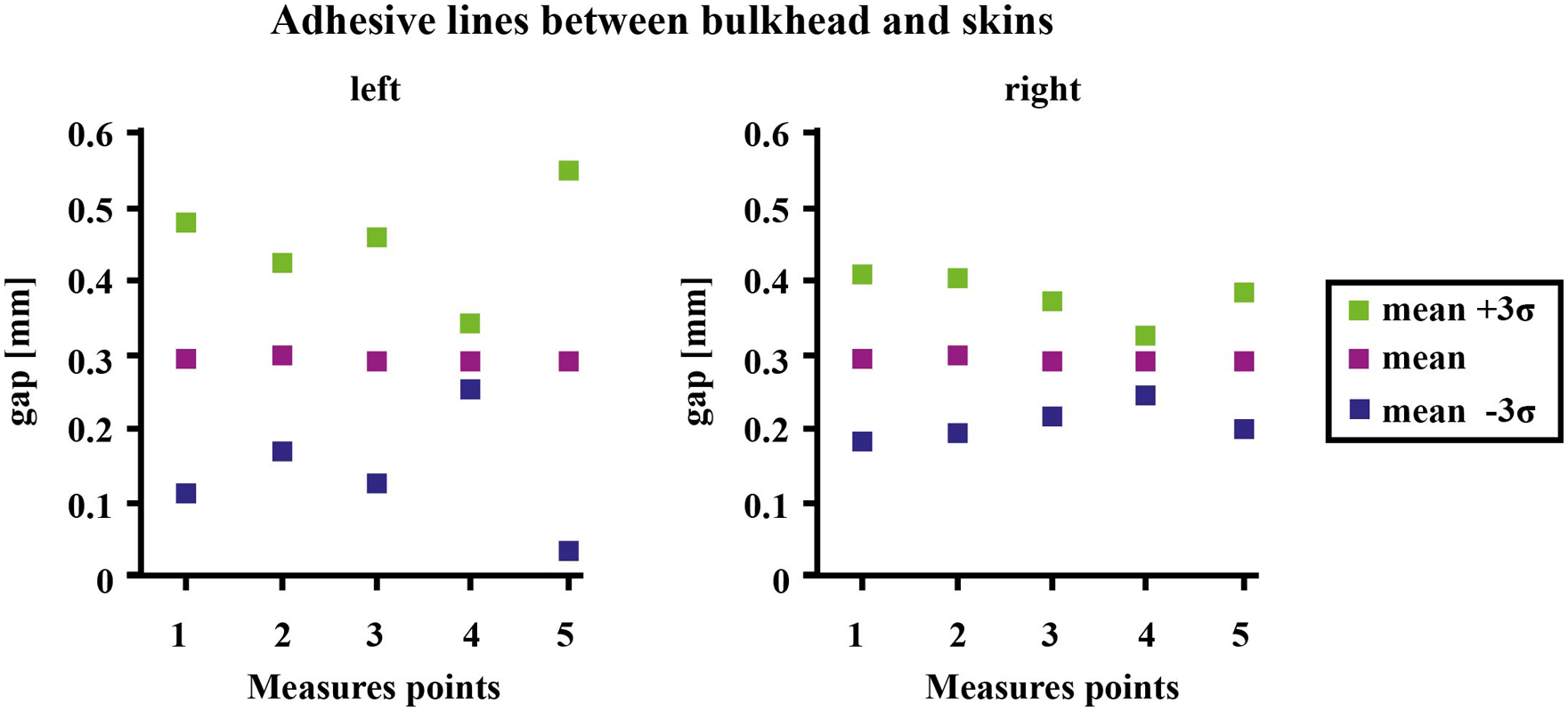
Distance of all the couples of points of bulkhead–skin gap.
Percentage of assemblies with interferences and with a non-uniform gap.
The percentage of assemblies with interferences at the interface between rib and spar is very high. This is due to the dimensional tolerance applied to the thickness of rib and spar surfaces that are faced. A reduction in the half of the dimensional tolerance does not avoid the problem. To identify the causes of the problem, and then the possible solutions, the software eM-Tolmate provides the opportunity to make a sensitivity analysis, as described in the following.
Drive motion requirements
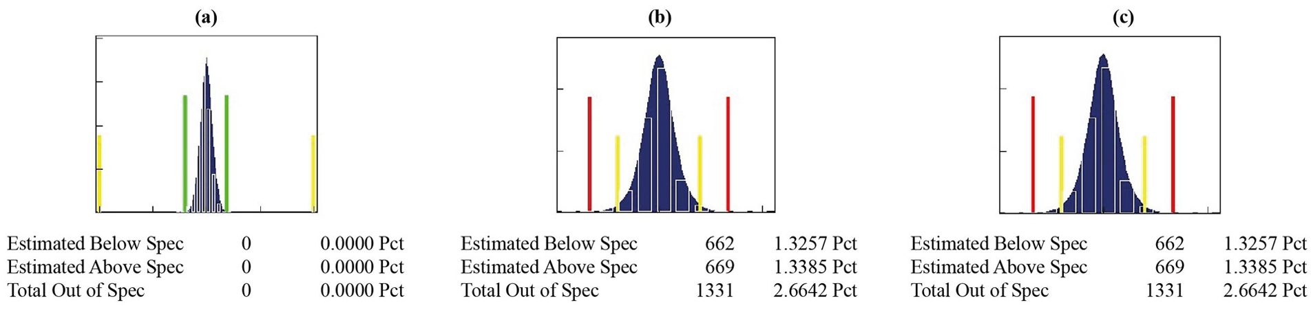
The percentage of parts whose angle between the two faced planes of rib and spar overcomes the limits of ±0.05° (non-conformities) is about 7% calculated as the rotation around the y-axis, 9% calculated as the rotation around the z-axis and 15% as the whole rotation, as shown in Figure 13. This is due to the dimensional tolerance applied to the thickness of the rib as found through the sensitivity analysis. Therefore, to reduce the value of this dimensional tolerance, there are two ways: to change the nominal value of the thickness and the new value needs to be verified by means of a structural analysis of the component; to improve the capability of the manufacturing process in order to obtain parts with smaller tolerances (i.e. a better quality).
Results of parallelism between spar and rib: (a) around y-axis, (b) around z-axis and (c) total effect.
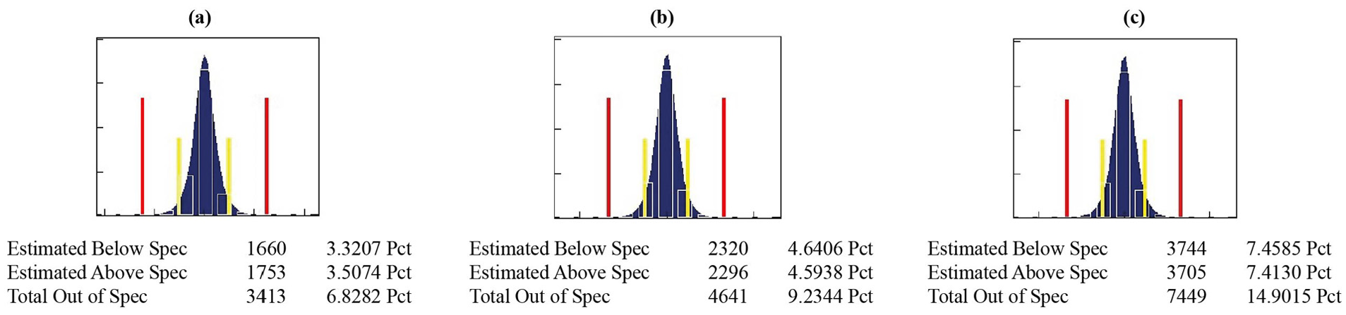
The percentage of parts whose angle between the rib’s axis and the bulkhead plane overcomes the limits of ±0.02° (non-conformities) is about 0% calculated as the rotation around the y-axis, 2.7% calculated as the rotation around the z-axis and 2.7% as the whole rotation, as shown in Figure 14. The obtained values are considered small.
Results of perpendicularity between rib’s axis and bulkhead’s plane: (a) around y-axis, (b) around z-axis and (c) total effect.
Finally, the percentage of parts whose control points on the skins overcome the limits of ±0.4 mm as regard to the nominal shape is equal to 0% (see Figure 15).
Results of left forward up point along (a) x, (b) y and (c) z axes, respectively.
Redesign of rib’s jig
A sensitivity analysis has been carried out to identify the causes of the high percentage of interferences at the interface between rib and spar. The results of Figure 16 show that the main contribution is due to the rib and in particular to the shacking of the rib as regards its jig.
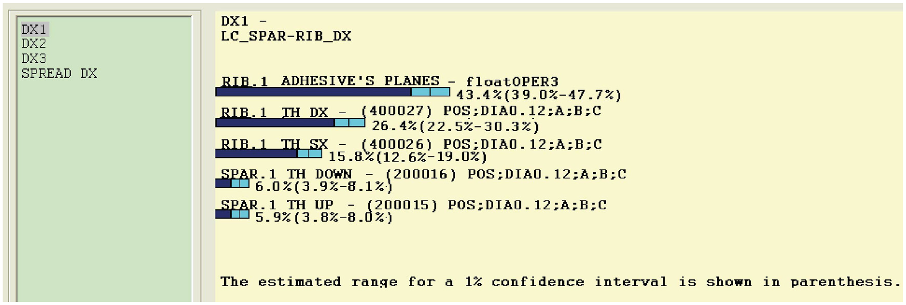
Sensitivity analysis of rib–spar adhesive line.
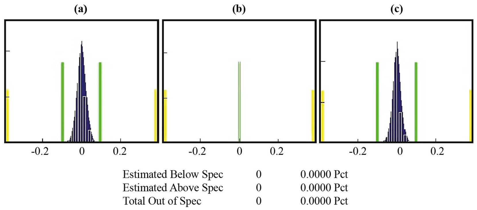
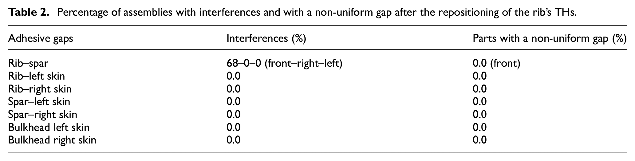
A solution is to reposition the THs on the rib according to Figure 17. This change brings the percentage of non-conformity to 0 (see Table 2). This solution determines an increase in the costs to make the component because a re-control of the structural stoutness of the part is necessary, and this probably obliges to increase the thicknesses, with a consequent increase in weight and costs. However, tolerance and contributors’ analyses have demonstrated that this is the only possibility to assemble the component by satisfying the required standards on adhesive gaps.
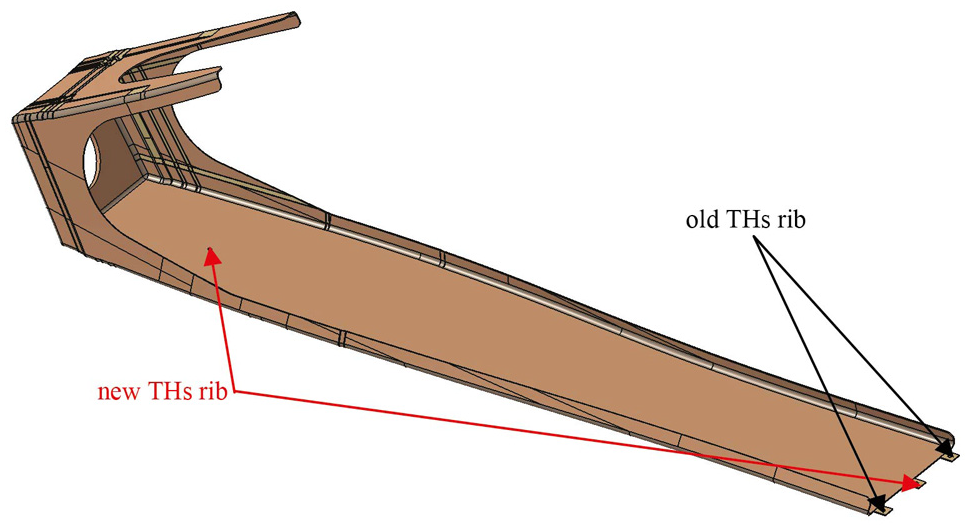
New THs of the rib.
Percentage of assemblies with interferences and with a non-uniform gap after the repositioning of the rib’s THs.
The choice to reposition the THs of the rib has a positive effect on the front line between spar and rib. In fact, the old percentage of non-conformity of the thickness (98.9%) is now of 68.8%. The great percentage of non-conformity depends on the shift of the probability distribution from the nominal value of the gap. To solve this problem, there are two possibilities: to translate the probability distribution on the nominal value of the gap or to change the nominal value of the gap by translating the gap on the probability distribution. The first solution is not possible, since the shift depends mainly on the tolerance imposed to the adhesive surface of the rib that cannot be changed for process constraints. The second solution is not possible too, since it would bring to redesign all the structure. Therefore, a feasible solution is to use an assembly jig that is provided of a system able to recover the gap between the spar and the rib. A draft of this type of tool is shown in Figure 18. This solution seems the only alternative to satisfy the constraints on adhesive gaps.
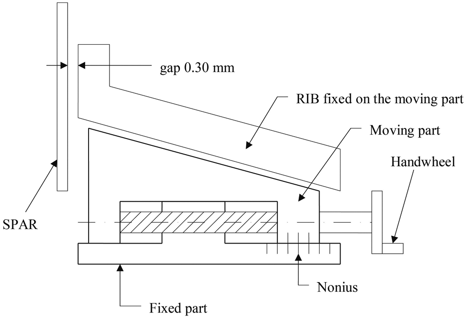
New assembly jig of the rib.
Conclusion
This work shows a method to verify whether the new designed tail beam of an aircraft in composite material may be assembled without interferences and whether its geometric specifications satisfy the functional requirements of the tail beam. The considered functional requirements are the trend of adhesive gaps at the interfaces between couples of components and the transmission of the drive motion from the main rotor to the tail rotor.
The analyzed adhesive trends depend on the tolerances assigned to the tail beam’s components and on the constraints due to the assembly sequence. The applied tolerances have been considered to follow a Gaussian distribution. The assembly sequence and the assembly jigs have been designed by satisfying the assembly functional requirements. A Monte Carlo approach has allowed to estimate the distribution of the adhesive gaps. To ensure an efficient assembly, interference conditions and excessive gap variation must be avoided. Dimensional and geometric tolerances that mostly affect the variance of the gap’s distributions have been identified through a sensitivity analysis. The results of simulations show a percentage of interferences of about 21% between rib and skins. To reduce this percentage, it is needed to decrease the position tolerance of the adopted TH. The front gap between rib and spar is extremely critical, since the dimensional tolerances applied to the thickness of the faced surfaces reduce this gap to 0. Therefore, it is needed to adopt a special jig able to recover the gap between the spar and the rib.
The performances connected with the motion drive of the tail beam have been evaluated by means of three parameters: the parallelism between the adhesive planes of rib and spar, the perpendicularity between the axis of the rib and the plane of the rib and the offset of the tail beam. The obtained results show that the critical parameter is the parallelism between the adhesive planes of rib and spar whose percentage of non-conformities is about 15%. This is due to the dimensional tolerance applied to the thickness of the rib. To reduce the value of this dimensional tolerance, there are two ways: to change the nominal value of the thickness and the new value needs to be verified by means of a structural analysis of the component and to improve the capability of the manufacturing process in order to obtain parts with smaller tolerances (i.e. better quality).
Footnotes
Declaration of conflicting interests
The author(s) declared no potential conflicts of interest with respect to the research, authorship and/or publication of this article.
Funding
The author(s) received no financial support for the research, authorship and/or publication of this article.