
Abstract
This article presents a new kind of software-defined electronic gearbox for gear hobbing based on a theoretical model of the hobbing process. The electronic gearbox implementation and structure are studied in an embedded numerical control system (numerical control/computer numerical control). Data flow among the electronic gearbox modules is also analyzed in the numerical control system. Special G-codes with parameters are designed, and the electronic gearbox control implemented through numerical control programming is realized in a custom gear hobbing numerical control system. In addition, two different hobbing methods (axial and diagonal) are tested on the computer numerical control platform. Results show that the hobbing computer numerical control with the proposed electronic gearbox functions accurately, and error is measured using tracking errors in different axes and gear pitch error of the machined gear. As will be shown, the gear pitch error was found to be 0.0147 mm for axial hobbing and 0.0176 mm for diagonal hobbing.
Introduction
Gear manufacture quality is strictly tied to the accurate motion of the multiple axes of a gear hobbing machine, that is, the hobbing machine’s mechanical transmission chain. All conventional hobbing or grinding machines use a mechanical gear train to control these motions (linear and rotary) accurately in relation to each other so as to generate the correct profile (involutes, hypoid, etc.) on the teeth of the workpiece being produced. The accuracy of the machined gear depends entirely on the gear train.1,2 Unfortunately, the performance of mechanical gearboxes critically depends on the machining precision of the gears, wear of the gears, continuing location accuracy, concentricity of bearings and other moving elements, and deflections caused by loading and thermal effects. These problems have been eliminated by replacing the gear train with a closed-loop electronic servo system, known as an electronic gearbox (EGB). 1 An EGB is a special multi-axis synchronous motion control technology. It can not only realize complex multi-axis coupled motion control but also has many advantages including low cost, high transmission precision and convenient ratio adjustment.
The Cranfield EGB control was first researched in the mid-1960s. 3 Based on a microprocessor, it has been developed into a commercially available multi-axis machine tool control system with high speed and precision. A hardware-style EGB, a version of the “phase-locked loop” is well known to electronic engineers. It can maintain the correct position between two shafts with an error of less than 1 part in 106, irrespective of speed, torque, power or gear ratio, as long as these fall within the system rating. 4 Much of the control system can be replaced by a digital computer, eliminating many of the restrictions imposed by hardware logic. Takeuchi and Katagiri 5 proposed a software-based EGB in 1993 and implemented the signal processing module with a computer, giving a wide transmission range. However, their method did not address the stability of the system and the problem of static offset.
The EGB has replaced the traditional mechanical transmission chain and has a number of advantages. For instance, they exhibit better motion accuracy and have a greater range of operating speeds. Unfortunately, EGB implementation details and control methods are rarely reported publicly. The traditional mechanical linear shaft, which is used to couple two or more loads in industrial applications, has been recently replaced by different multi-motor strategies.6,7 There are several common synchronization techniques for different standard industrial applications, including master-slave, cross-coupled,8–10 bi-axial cross-coupled control, 11 electronic (virtual) line-shafting 12 and relative coupling. However, the gear-generation process is different from general numerical control (NC) machining,13–16 that is, turning and milling machine tools. Gear production depends on the coupled movement of a hob cutter axis, gear blank axis and the additional movement of the feeding axes, all of which is controlled by an EGB. The machining accuracy of a gear is affected not only by the contour precision of the cutting tool path trajectory but also by the synchronization precision of the hob axis and gear blank axis. So, existing synchronous motion control methods cannot be directly used for gear machining.
Based on an analysis of hobbing processing technology, a theoretical model for use in the EGB is proposed in this article. Implementation methods are studied in embedded NC systems based on a hardware platform composed of a combination of advanced RISC machine (ARM), digital signal processor (DSP) and field-programmable gate array (FPGA). The overall architecture of the computer numerical control (CNC) software is designed to be modular and reconfigurable. The internal information flow of the CNC software is analyzed in detail and the EGB can be embedded in a gear machining CNC system seamlessly. The EGB control was implemented with NC programming in a CNC system. Through experimental verification, we find that the EGB control accuracy (gear pitch error) meets the requirements of gear machining inner-link transmission.
The remainder of the article is arranged as follows: the structure of the proposed EGB and the theoretical model of the six-axis hobbing EGB are first introduced in section “Structure and theoretical model of the EGB.” Next, the hardware platform of the custom hobbing CNC is given in section “EGB embedded in a hobbing CNC.” Also in section “EGB embedded in a hobbing CNC,” the data flow among the modules is analyzed in the hobbing CNC. In section “Realization of EGB,” the implementation details of the hobbing EGB on a six-axial CNC machine are presented and the tracking error and gear pitch error are analyzed. Finally, section “Conclusion” concludes the article.
Structure and theoretical model of the EGB
Structure of the EGB
There are two types of EGBs: the Master-Slave EGB (shown in Figure 1(a)) and the Parallel-Coupled EGB (shown in Figure 1(b)). In a Master-Slave EGB, the output speed of the master shaft serves as the speed reference for the slave shaft, implying that any speed or load disturbances applied to the master will be reflected and followed by the slave. 6 In contrast, a Parallel-Coupled EGB controls every axis independently to realize the transmission.
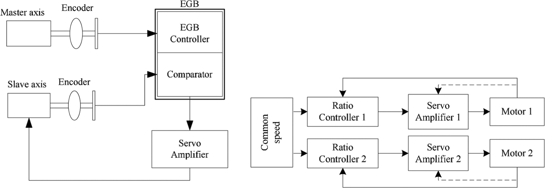
The structure of the EGB: (a) Master-Slave EGB and (b) Parallel-Coupled EGB.
Each EGB type has advantages and drawbacks. First, the transmission accuracy of the Master-Slave EGB is only affected by the tracking precision of the slave axis, while the Parallel-Coupled EGB is affected by the accuracy of both axes. Thus, the Master-Slave can achieve higher transmission accuracy. Furthermore, the input signal of the slave axis is the feedback signal of the master axis; however, during the actual gear machining process, the speed of the master axis is changing causing a certain tracking lag at the instant of the spindle start or speed change. This lag is not apparent between axes of a Parallel-Coupled EGB, because both axes will reproduce any tracking error. Due to the movement characteristics of the gear hobbing processing, the proposed EGB follows a master-slave structure in this article.
Theoretical model of the hobbing EGB
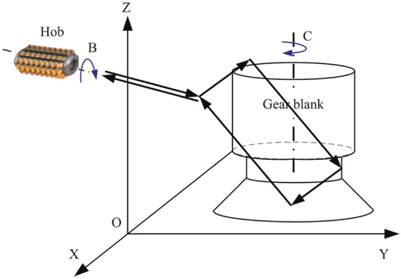
A gear can be shaped (grind/cut) by synchronizing the workpiece axis rotation to the tool axis (grinding axis/hob) rotation. Two spindles can be used as the tool axis and the workpiece axis. To synchronize these two axes, a Master-Slave EGB is used. In a Master-Slave EGB, a synchronous pulse is produced from the feedback pulse of the position detector attached to the tool axis (master axis) in the motor control, and the workpiece axis (slave axis) rotates with the pulse. The feedback pulse from the master side to the slave side is transmitted between spindle amplifiers. An illustration of the gear hobbing machine axes is shown in Figure 2, in which B is the hob spindle, C is the workpiece axis, X is the radial feed axis, Y is the tangential feed axis, Z is the axial feed axis and A is the hob installation angle adjustment axis.
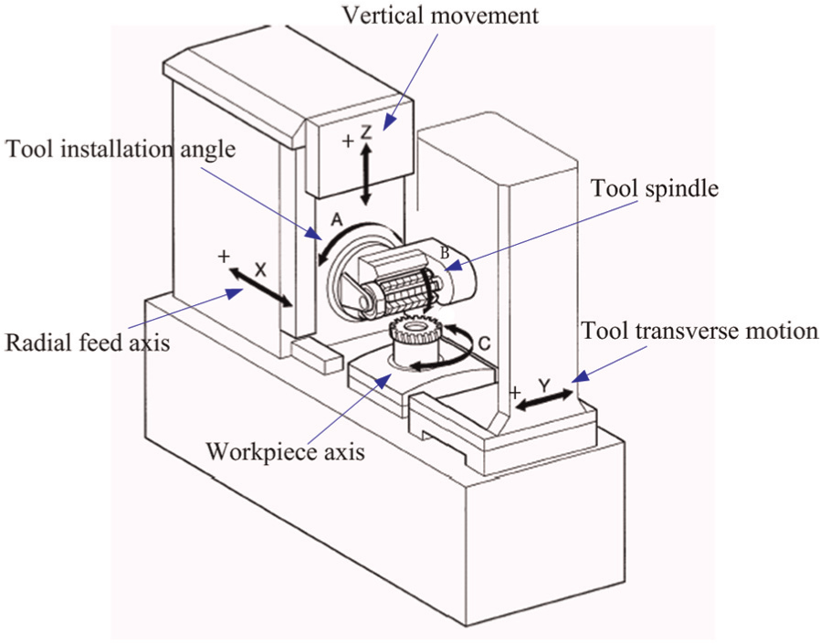
Illustration of the gear hobbing machine axes.
A theoretical control model of the Master-Slave EGB is illustrated in Figure 3, where
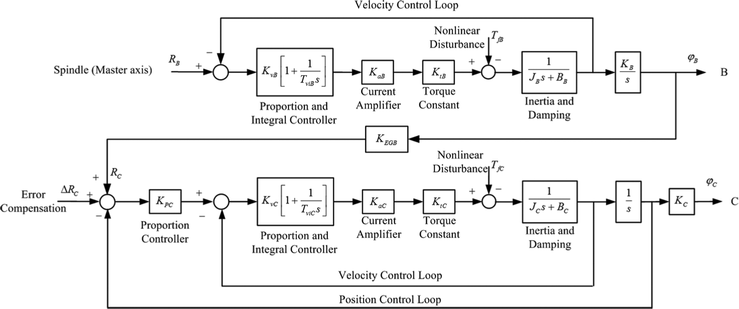
Theoretical control model of the Master-Slave EGB.
Gear hobbing is implemented using the relative motion of the hob axis and workpiece axis. When machining helical gears, the hob must be mechanically tilted to match the required helix angle. In addition, the ratio between the rotational speeds of the table and hob must be modified by a term proportional to the linear through-feed speed and the tangent of the helix angle. When a helical gear is to be produced or the width of the gear is large enough, there must be vertical movement along the Z-axis so that compensation of the workpiece axis rotation is needed according to the travel distance on the Z-axis. Similarly, compensation of the tool transverse motion, which is used in the “diagonal hobbing” method, is needed according to the travel distance along the Y-axis. These helical gear and tool transverse motion compensations are performed by adding compensation pulses calculated as
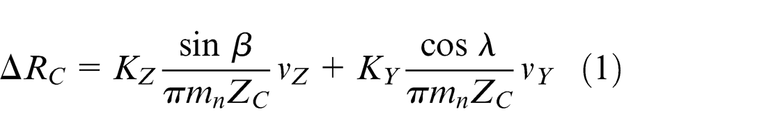
to the workpiece axis. In equation (1),
Using the above analysis, two EGB models (labeled as EGB-1 and EGB-2) can be constructed and are given in Figures 4 and 5. The difference between these two structures is the synchronous signal source, which is used in the EGB computations. The values of
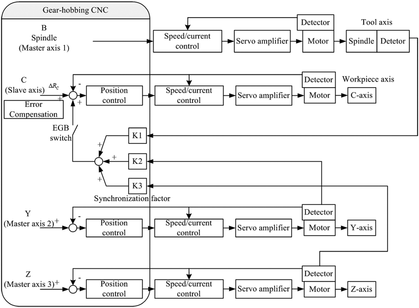
Gear hobbing EGB-1.
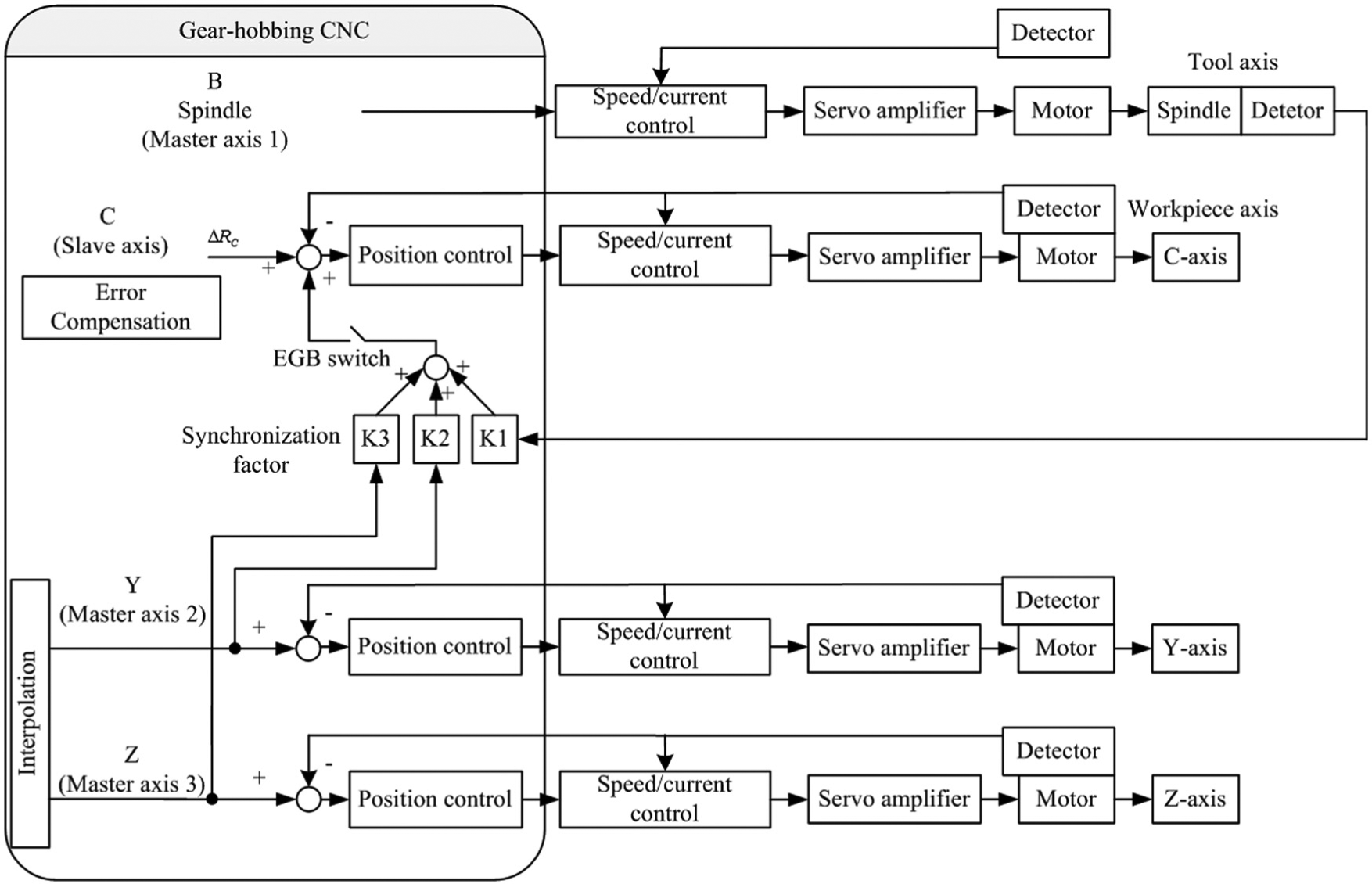
Gear hobbing EGB-2.
If the EGB system is designed so that the position loop and the inner velocity loop controllers are bounded-input bounded-output (BIBO) stable, as shown in Figure 3, then the designed multi-axis EGB system is also BIBO stable. Considering equation (1), we can see that the input of the C-axis is bounded because the B-axis is BIBO stable.
Gear pitch error analysis
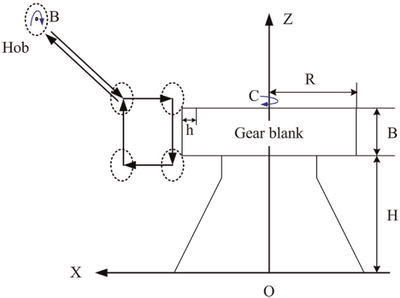
In this section, the source of pitch error is analyzed, and an instantaneous pitch error formula is deduced. Considering the generating process kinematics, in the case of a hob with one start, each hob tooth penetrates into the next gear gap in the same generating position, removing a chip with the same geometry as in the previous gear gap. As illustrated in Figure 6,
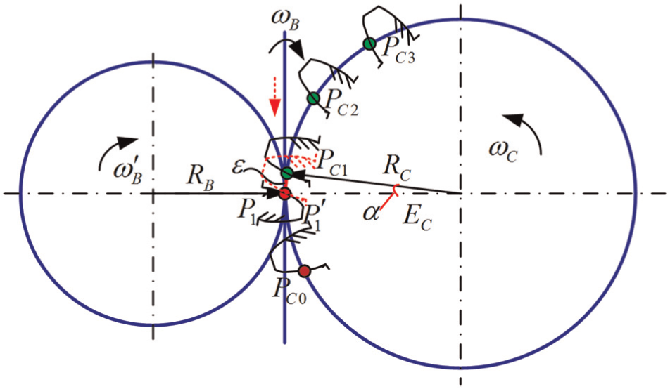
Analysis of pitch error.
As shown in Figure 6, given that
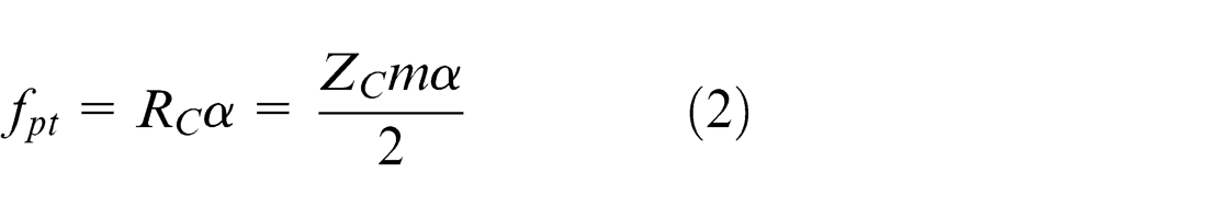
where
EGB embedded in a hobbing CNC
The gear hobbing CNC hardware platform used in this research is illustrated in Figure 7. It is composed of an ARM9 (EP9315) microcontroller and the DSP TMS320C6713. The complex operation and real-time control are performed by the TMS320C6713 DSP. Data exchange and background communication are handled via the host port interface (HPI). The application layer software is based on the ARM9, WinCE operating system. The software components used include file management, system and process parameter settings, processing status display, parametric automatic programming, graphic simulation, alarm information and communication functions. The real-time control layer software is based on the BIOS of the TMS320C6713, which mainly includes the proportional–integral–derivative (PID) controller, interpolation, EGB, programmable logic controller (PLC) processing 17 and the input/output (I/O) actuation functions.
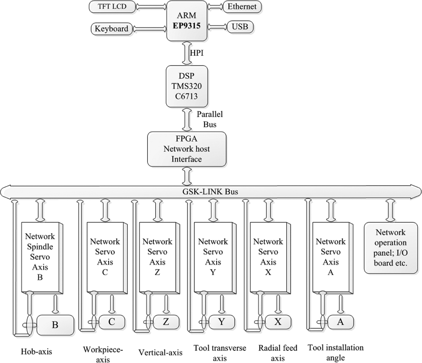
Hardware platform of the hobbing CNC.
As shown in Figure 8, the CNC software consists of an interpreter, a look-ahead module, a rough interpolator, a fine interpolator and a position controller. The ring buffers are used for synchronization of the data flow between the modules. They are found between the interpreter and the look-ahead module, between the look-ahead module and the acceleration/deceleration (acc/dec) controller, between the acc/dec controller and the rough interpolator, between the rough interpolator and the mapping module and between the fine interpolator and the position controller. 18
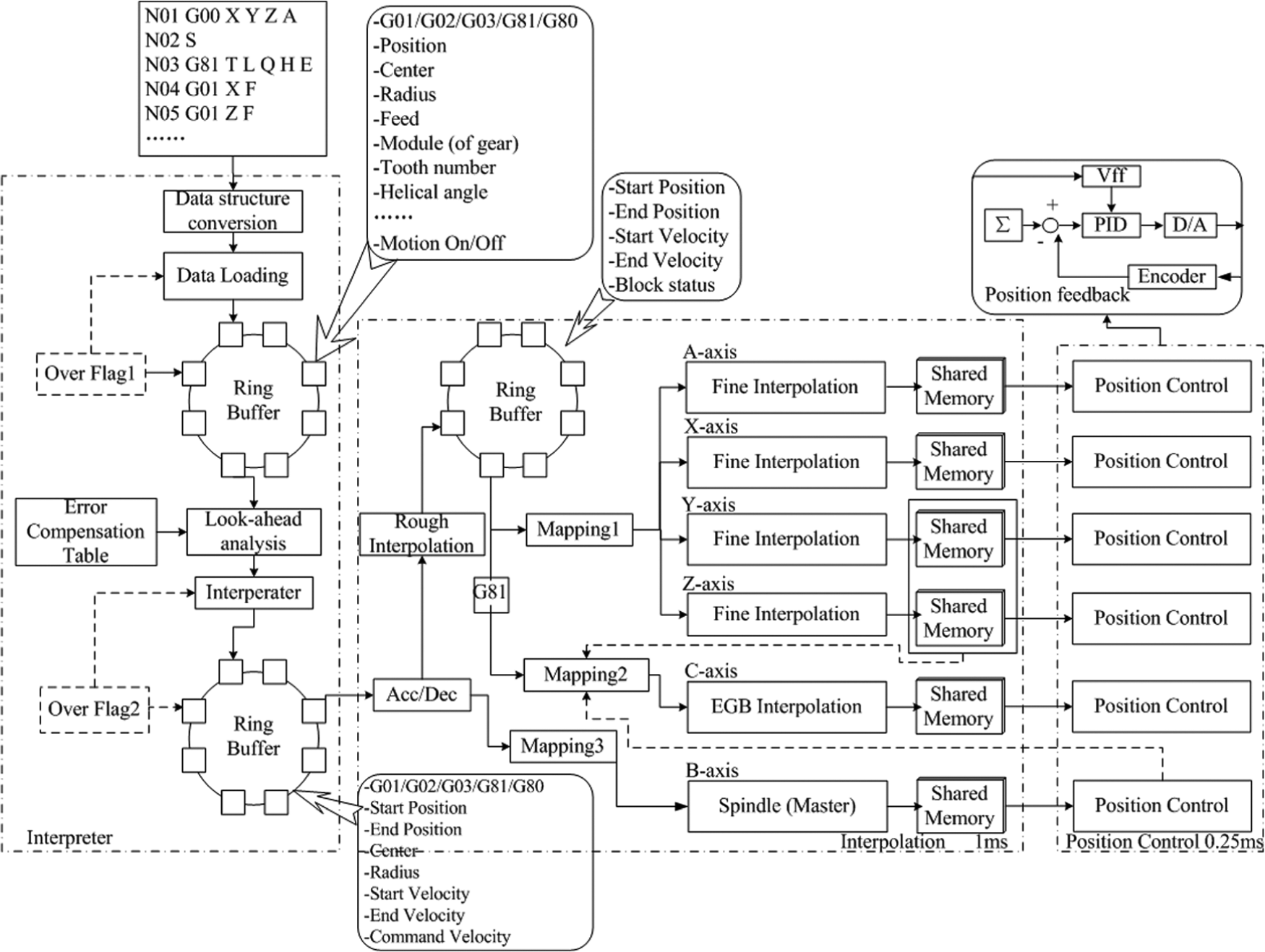
Data flow between the modules in the hobbing CNC with the EGB.
First, G-codes generated by the automatic programming software implemented on the ARM microcontroller are downloaded to the data buffer of the TMS320C6713 DSP via the HPI, after data structure conversion. The buffer “over flag” decides whether to continue downloading data or not, based on the consumption of data. The feed rate and coordinate positions of each axis can be obtained in the ring buffer through look-ahead analysis and interpretation. Finally, after acc/dec processing, rough interpolation, mapping and fine interpolation, the input data for the PID controller are obtained.
G81 is the special code for opening the EGB, and G80 is the code for closing the EGB. NC codes can set the EGB function flag during code interpretation. If the EGB branch is ineffective, the C-axis can be regarded as a general CNC shaft. When the EGB interpolation branch is effective, the C-axis will follow the movement of the B-axis, Y-axis and Z-axis. The law of motion is given by
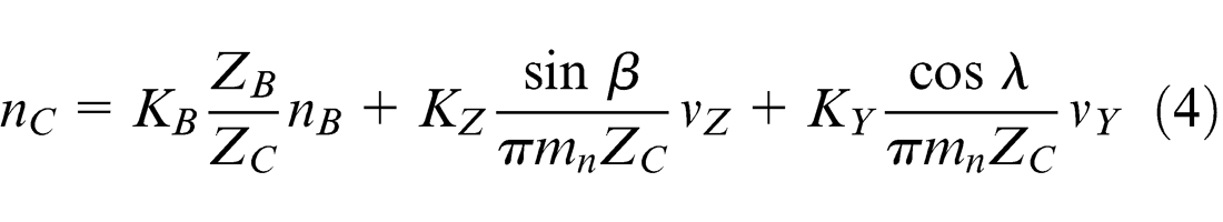
where
Realization of EGB
Experimental setup
The experimental platform used in this article is a custom, six-axis hobbing CNC, which contains six axes (X, Y, Z, A, B and C). The structure of the platform is shown in Figure 9. Panasonic A4-type alternating current (AC) servomotor with built-in velocity control loops drives all the axes. The hardware of the hobbing CNC, as described in section “EGB embedded in a hobbing CNC,” performs coordinate control in the position loop, which includes sending motion commands to and receiving feedback signals from the servomotor. The servo’s encoder produces 10,000 pulses every rotation and the screw lead is 5 mm so that the resolution is 0.5 µm.
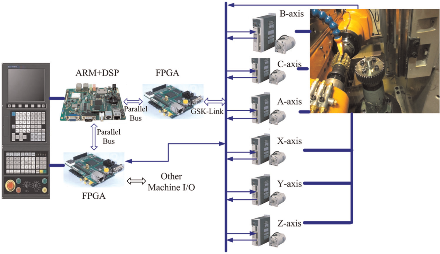
Experimental six-axis hobbing CNC.
Experimental parameters
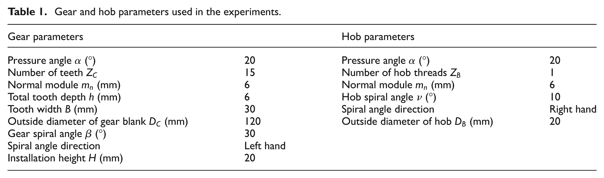
The parameters of the gear and hob are shown in Table 1. After inputting these parameters in the gear- and hob-parameter interface, a processing method is chosen in the process interface. Finally, the G-codes are generated by the ARM automatic programming software.
Gear and hob parameters used in the experiments.
In the next section, the axial hobbing and diagonal hobbing methods will be used to prove the effectiveness of the proposed EGB for CNC hobbing. As illustrated in Figures 10 and 11, the difference between the two kinds of processing methods is that there is more Y-axis movement in the diagonal hobbing method, that is, transverse motion of the tool. The two methods are explained below.
Axial hobbing method.
Diagonal hobbing method.
When machining a cylindrical spiral gear by the axial hobbing method, coordination exists between three axes: the B-axis, C-axis and Z-axis. The EGB should be open before the other travel axes are moved. When the hob spindle runs, the C-axis will follow with a synchronous pulse, which is produced from the feedback pulse of the position detector attached to the hob axis. Then, the hob feeds to the full tooth depth gradually along the X-axis. Subsequently, the hob gradually cuts over the entire tooth width along the Z-axis, while at the same time the X coordinates remain unchanged. During the entire process, the B-axis and C-axis paths must be kept in strict generating motion, which is controlled by the EGB.
When machining a cylindrical spiral gear by the diagonal hobbing method, coordination exists between four axes: the B-axis, C-axis, Y-axis and Z-axis. As in the axial hobbing method, the EGB should be open before other travel axes are moved. When the hob spindle starts, the C-axis will follow with the synchronous pulse, which is produced from the feedback pulse of the position detector attached to the hob axis. Then, the hob feeds to the full tooth depth gradually along the X-axis. After that, the hob gradually cuts over the entire tooth width along the special diagonal trajectory of the Y-axis and Z-axis (rather than the Z-axis only), while at the same time, the X coordinates remain unchanged. The B- and C-axes must be strictly generating motion during the whole movement path, which is also controlled by the EGB.
Experimental results and analysis
Axial hobbing method
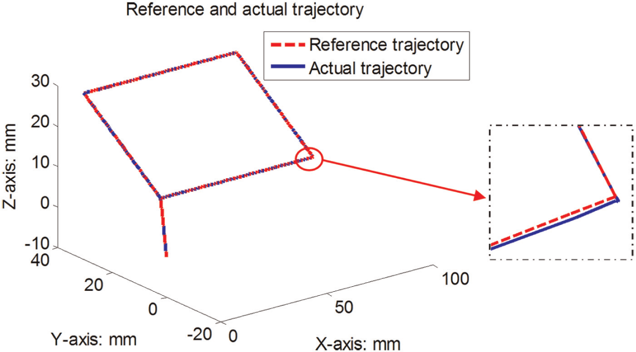
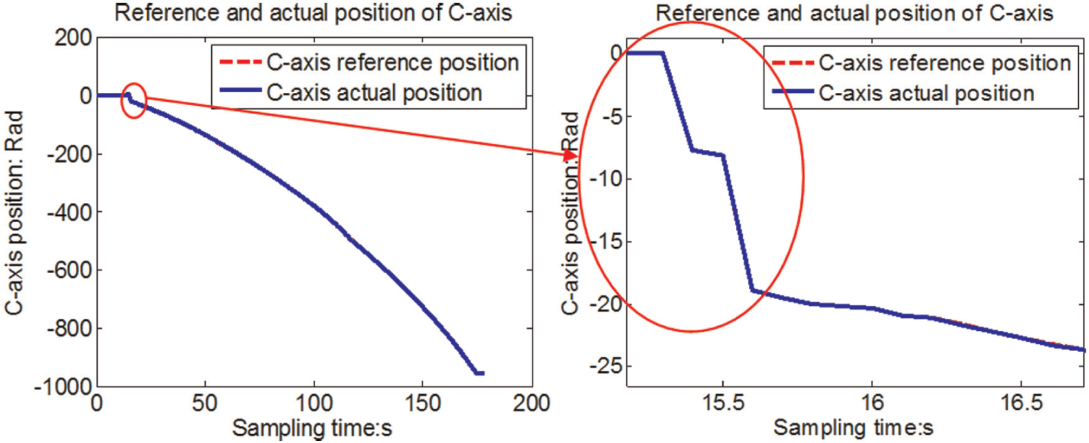
In this section, experiments using the axial hobbing method are described, which were carried out on the six-axis hobbing CNC, with a spindle speed of 500 r/min. The reference and actual trajectory of the hob are illustrated in Figure 12. The C-axis follows the B-axis and Z-axis during the entire machining process. The movement of the C-axis followed equation (4), and its reference and actual positions are illustrated in Figure 13. It is evident that there is an instantaneous position change at the moment when the EGB is opened because the spindle speed was fast and the acceleration time of the C-axis was short.
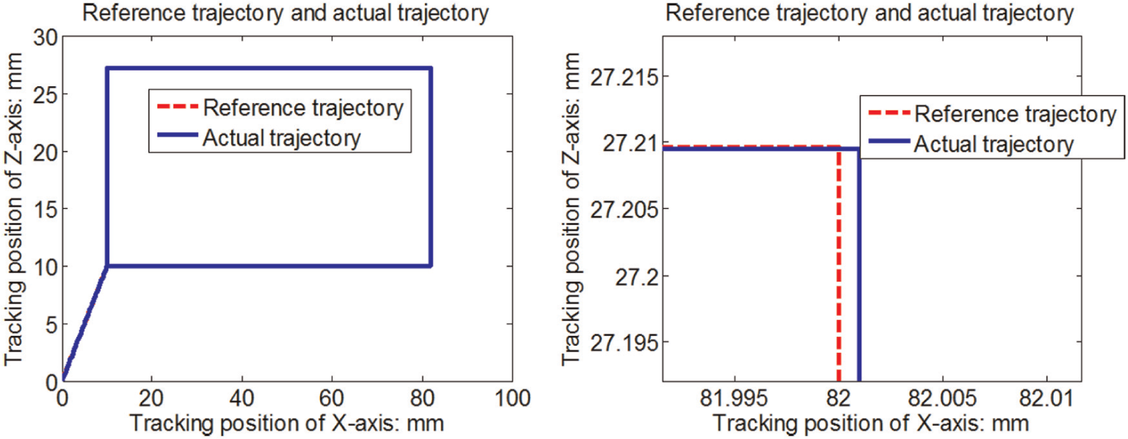
Reference and actual trajectories by using the axial hobbing method.
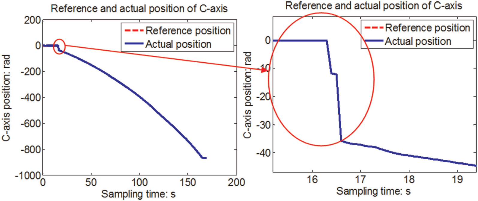
Reference and actual positions of the C-axis by using the axial hobbing method.
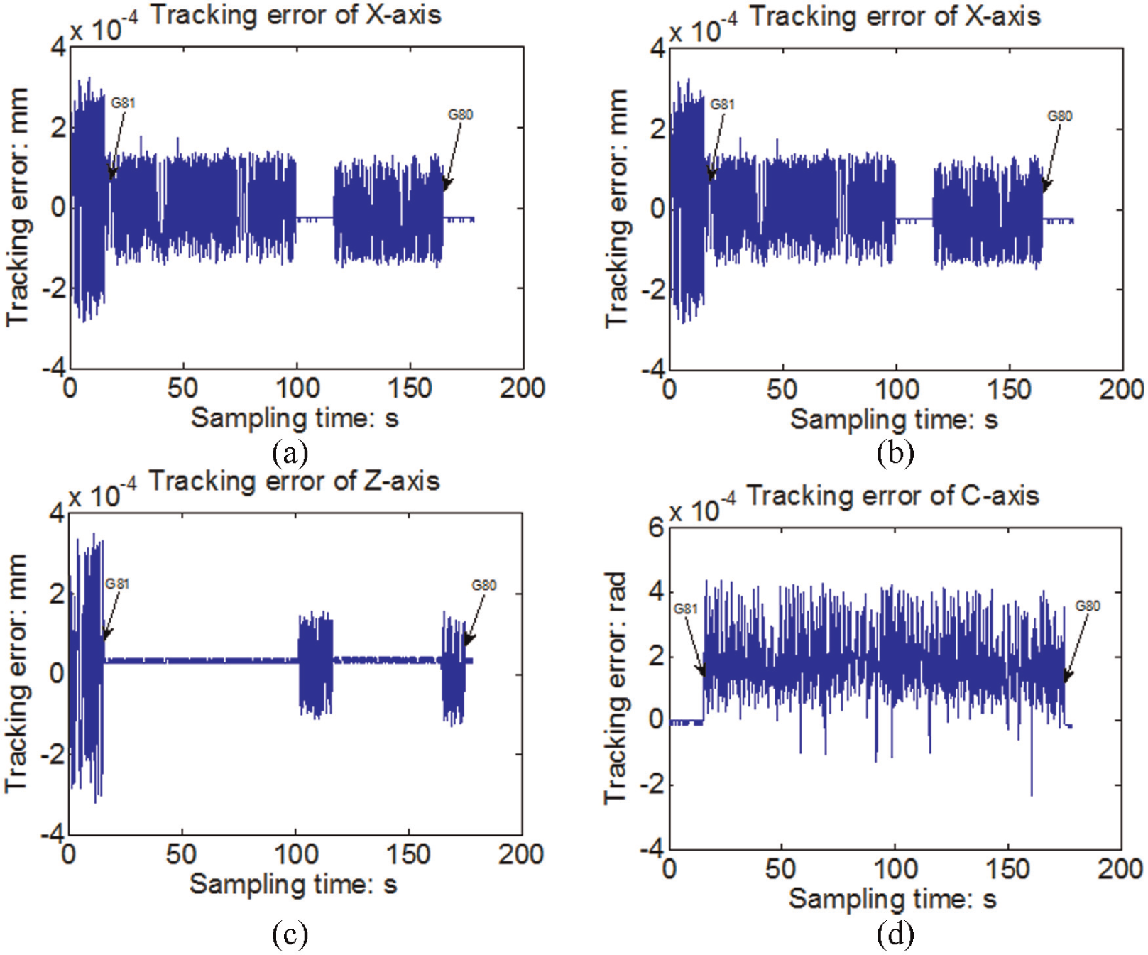
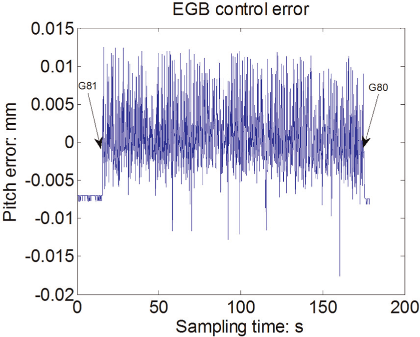
The tracking error throughout the axial hobbing movement process is shown in Figure 14. Before the G81 command was executed, the X-axis and Z-axis moved to a reference point that was close to the workpiece. Then, the EGB was opened by the G81 command, and the hob was gradually fed to the full tooth depth along the X-axis. After a short pause, the hob was fed along the Z-axis over the entire tooth width, as the hob cut along the X-axis and Z-axis. Finally, the EGB was closed by the G80 command. During the cutting process, the single-axis tracking error of the X-axis and Z-axis was both less than 0.4 µm, and the tracking error of the C-axis was less than 0.0006 rad. The pitch error of the workpiece reflects the accuracy of EGB and is illustrated in Figure 15, with a maximum absolute error less than 15 µm.
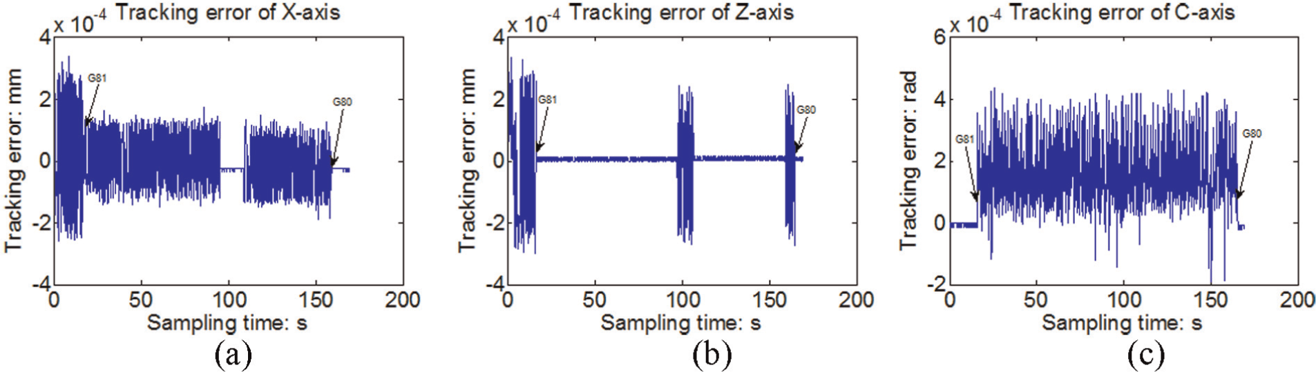
Tracking error analysis during motion: (a) tracking error of X-axis, (b) tracking error of Z-axis and (c) tracking error of C-axis.
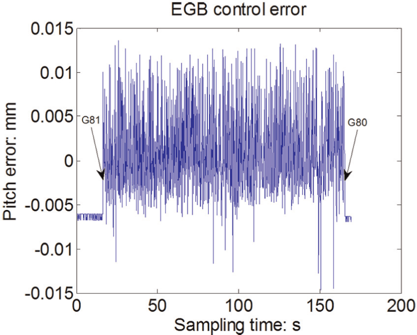
Gear pitch error caused by the EGB.
Diagonal hobbing method
In this section, the diagonal hobbing method is evaluated. In this case, the spindle speed was 900 r/min. The reference and actual trajectories are illustrated in Figure 16. The C-axis followed the B-axis, Y-axis and Z-axis throughout the machining process, and its reference position and actual position are illustrated in Figure 17. There is also an instantaneous position change at the moment when the EGB is opened, as the C-axis attempts to keep up with the spindle.
Reference and actual trajectories by using the diagonal hobbing method.
Reference and actual positions of the C-axis by using the diagonal hobbing method.
The tracking error during the diagonal hobbing motion process is shown in Figure 18. It can be seen that the single-axis tracking errors of the X-axis, Y-axis and Z-axis are all less than 0.4 µm during the hobbing process, and the tracking error of the C-axis is less than 0.0006 rad. The estimate of the gear pitch error in the gear diagonal hobbing process is illustrated in Figure 19, and the maximum absolute error is less than 18 µm.
Tracking error analysis during motion: (a) tracking error of the X-axis, (b) tracking error of Y-axis, (c) tracking error of Z-axis and (d) tracking error of C-axis.
Gear pitch error caused by the EGB.
From Figures 12–19, we can conclude that the hobbing CNC and the EGB can work correctly for the examples tested. The C-axis follows the rotation speed of the spindle and the feed rate of the other servo shaft. From Figures 14 and 18, we can see that the tracking error of each axis is very small. Here, we use the gear pitch error as the performance metric of the EGB. As shown in Figures 15 and 19, under the control of the EGB, the maximum gear pitch error is 0.0147 mm in the axial hobbing movement process, and the maximum gear pitch error is 0.0176 mm in the diagonal hobbing movement process. The results show that the proposed EGB is effective.
Conclusion
A theoretical model was proposed for EGB software control and was evaluated using a custom hobbing CNC. Implementation methods for the software-based EGB were studied in the embedded CNC system. Data flow among the CNC modules was also analyzed in detail. Finally, experiments were conducted using a six-axis hobbing CNC with two different hobbing methods: axial hobbing and diagonal hobbing. The tracking error and gear pitch error were analyzed for both the experiments. The results show that the software-based EGB is effective, although the tracking error of the C-axis could be further improved. Future studies will focus on a synchronous control method of the C-axis.
Footnotes
Declaration of conflicting interests
The authors declare that there is no conflict of interest.
Funding
The authors would like to thank the National Natural Science Foundation of China (No. 51275147), the Important National Science & Technology Specific Projects (No. 2012ZX04001021) and the Fundamental Research Funds for the Central Universities for supporting this research under grant.