
Abstract
Non-circular helical gears, having the advantages of cams and cylindrical gears, are widely used on various occasions, whose precision machining has always been a research focus. With the accuracy requirements increasing of non-circular gears, upgrading non-circular gear hobbing models is more and more important. This paper takes the non-circular helical gears hobbing with moving axis as the research object, and establishes the ellipse standard system for high-order non-circular gears, and derives the linkage mathematical model for machining helical non-circular gears with hobbing cutters. In this paper, a preliminary design for the processing of non-circular gear hobbing is carried out.
Non-circular gear, combining the advantages of a circular gear and a cam mechanism, can accurately transmit high power with a variable transmission ratio, which plays an important role in realizing precise non-circular trajectory movement. 1 Since there are many types and shapes of non-circular gears, and the application of gear hobbing linkage control in the processing of high-end non-circular helical gears is immature, it is difficult to manufacture and the accuracy is low. In order to play the unique advantages of non-circular gear transmission fully and meet the actual needs of mass manufacturing, it is of great value to study high-precision non-circular gear joint control technology.
In recent years, many scholars have carried out a lot of research work on the optimization design, mechanism application, vibration control of special-shaped and complex gears. 2 Xiao et al. 3 studied the influence of drive ratio on torque and transmission efficiency, and proposed a method for optimal design of tooth profile. Wang studied the transmission ratio of multi-stage gear trains and proposed an optimal number of stages with a compact structure. 4 This paper reviews the advancements in HSMC, and reveals the relationships among inherent attributes of workpiece materials, processing parameters during HSMC, and evolution of machined surface properties will be a potential breakthrough direction. Although scholars have made some useful explorations on the processing of non-circular gears, the current processing schemes cannot be fully applied to the processing of non-circular helical gears. There are still technical difficulties in mass production of helical non-circular gears.
In order to establish a hobbing non-circular helical gear machining model that can be combined with a CNC system to solve the gear machining problems such as the pitch curve concave, this paper on the basis of analyzing the characteristics about elliptical family closed gear transmission, proposing the theory of non-circular helical gear transmission based on the target transmission ratio, designing the main and driven wheel pitch curves according to the maximum and minimum transmission ratio requirements, which can be widely used in engineering practice.
Non-circular gear transmission based on variable transmission ratio of moving axis
Features of non-circular helical gears
The most prominent transmission feature of non-circular gears is the variable transmission ratio (changes according to a certain rule). 5 Non-circular helical gears can be used not only to transmit variable transmission ratio rotation between parallel shafts, but also to transmit variable transmission ratio rotation between intersecting shafts. In addition, under the condition that the modulus and the number of teeth remain unchanged, the closedness of the pitch curve can be satisfied by the inclination angle of the helical non-circular gear.6,7
Pitch curve of helical non-circular gear
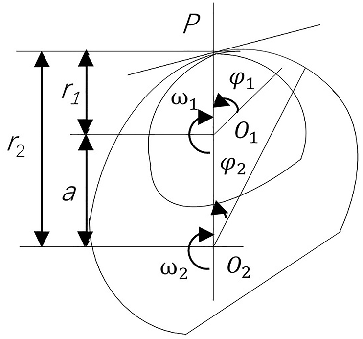
External gear meshing transmission and pitch curve are shown in Figure 1. Set the center distance of the gear pair to a, the angle of master gear rotation to

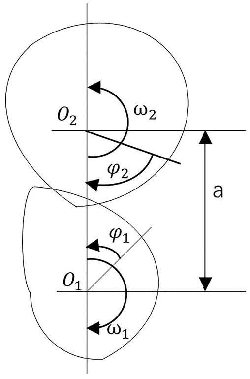
External gear meshing transmission and pitch curve.
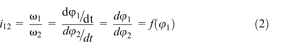
Then the gear sub-drive ratio function i12 is
Within the range of
At any instant of two helical non-circular gears, there is an instant center p whose relative motion speed is equal to zero.
8
Point p is located on the connecting lines O1 and O2, and satisfies the condition
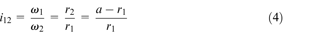
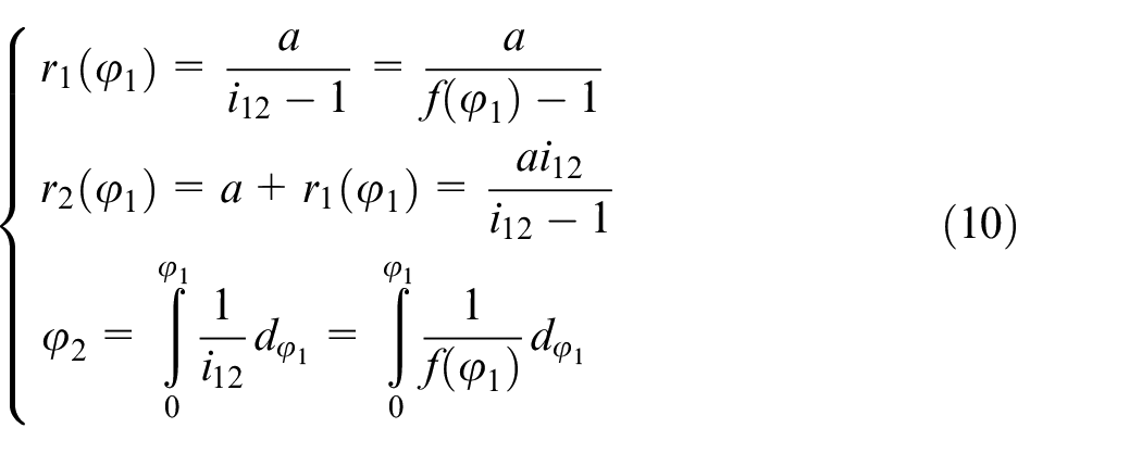
Unlike spur gears, the transmission ratio i12 of non-circular gears is variable, that is, the position of instant center p, r1, and r2 are changed. 9 The trajectory of the instant center on the helical non-circular gears 1 and 2, that is, the instant center line of gears is the pitch curve of the gear, which is called the pitch circle line in the spur gear. The pitch curve equation of driving wheel 1 can be obtained as
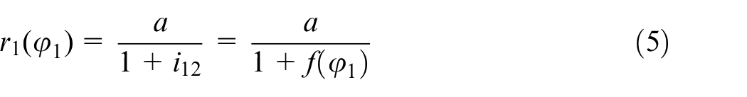
Then, the pitch equation of the driven wheel 2 is
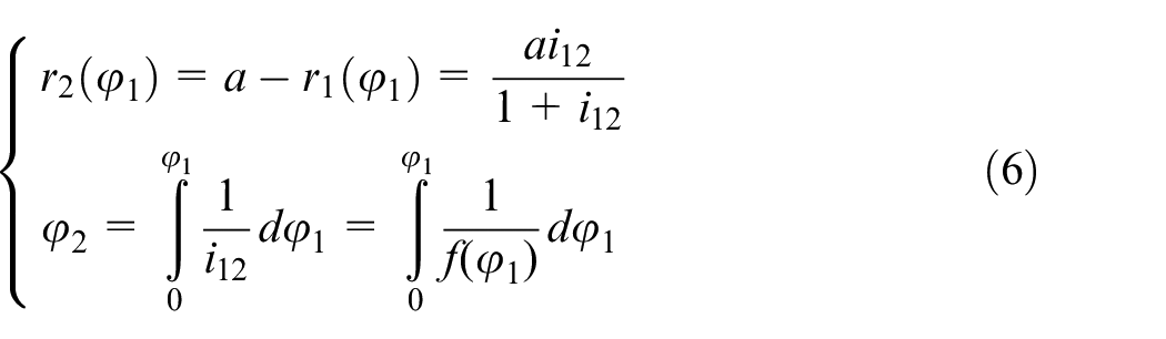
The above formula is the pitch curve equation of external meshing helical non-circular gear represented by polar coordinates (r, φ).
In the transmission ratio

Then the transmission ratio function i12 is
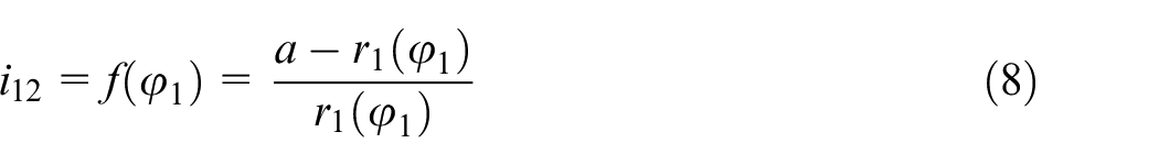
The pitch curve equation of the driven wheel is
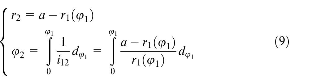
The internal gear transmission and pitch curve are shown in Figure 2. If the driven wheel 2 is an internal gear, the
Internal gear transmission and pitch curve.
The ellipsoid standard system of moving shaft gear transmission
In this study, the relative motion of the axis is seen as a motion spin, so the dynamic shaft gear transmission becomes the discussion of the motion and geometric relationship between the three spins, and the cylindrical coordinate system established by the two transmission gears is selected as the basis. 10 In this paper, auxiliary geometric elements such as instantaneous axis, instantaneous axis surface, axial surface, and pitch surface are integrated to establish the ellipsoid standard system of moving shaft gear transmission.
According to the three-axis theorem, the instantaneous axis of the driving and driven gears can be calculated according to the following formula,

In the formula (11):
From the derivation, the following formula can be obtained
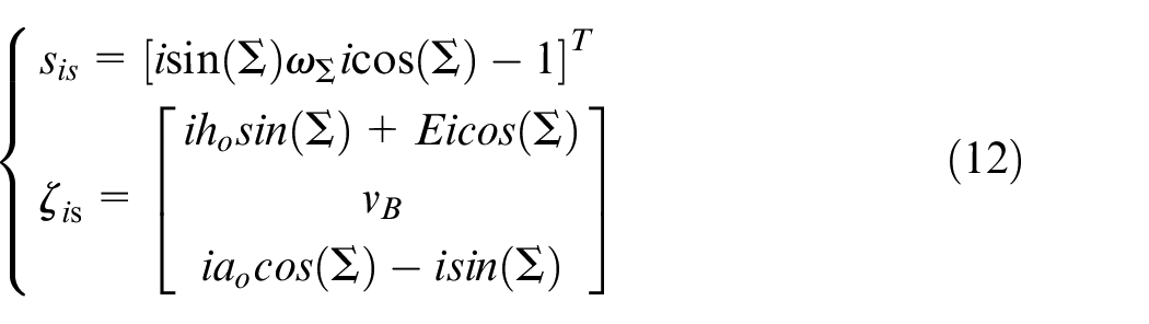
In the formula(12)
According to the basic definition of the screw, the instantaneous shaft screw can be obtained
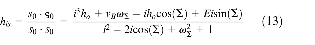
In the formula (13),
So that the direction vector of the instantaneous axis can be determined
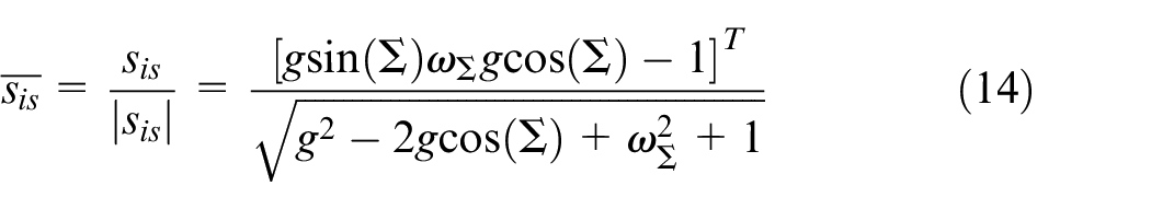
Further, the normal vector of the instantaneous axis can be obtained
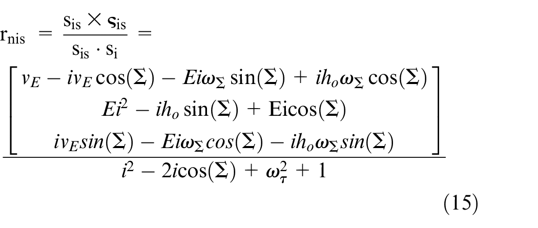
Thus, the linear equation of the instantaneous axis

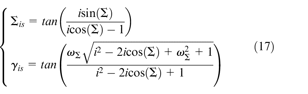
In the formula (16), t is the distance from any point on the straight line to the position vector rnis. The pose of the instantaneous axis in the coordinate system s0 is shown in Figure 3. Its spatial pose can be expressed by the direction angles Σis and γis. According to the formula, the calculation formula can be obtained as follows:
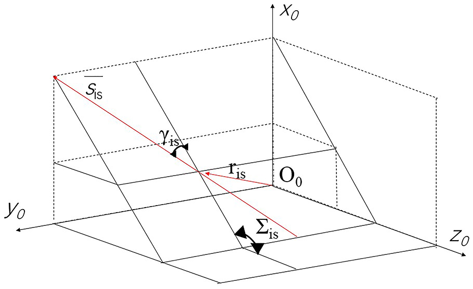
The spatial position of the instantaneous axis.
Another important concept of gear kinematics is the instantaneous exode, which is an important reference for gear design and manufacturing. 11 The instantaneous axis surfaces of the driving and driven wheels can be obtained by rotating the instantaneous shafts around the respective axes as follows:
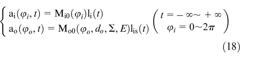
For the most general case, the instantaneous axis of the gear drive is a pair of hyperboloids. 12 When the transmission ratio is constant, it is a standard linear rotary hyperboloid, as shown in Figure 4. When the gear ratio changes, it is a pair of nonlinear hyperboloids.
Space linear hyperbolic revolution.
Axial surface refers to the curved surface formed by all possible instantaneous shafts in a gear transmission of a given pair of transmission shafts. 13 Accordingly, by rewriting equation (18) with the transmission ratio i and the parameter t as independent variables, the axial plane equation can be obtained as follows:
In fact, from the perspective of the screw, cylindroid is a linear combination of the driving and the driven wheel.
This article redefines the reference curve of the hypoid gear transmission to define the pitch surface. According to this definition, in the case of constant speed ratio, the pitch surface is a pair of conical surfaces, which conforms to the existing definition of hypoid gear pitch surface.14,15 With reference to the change of transmission ratio, the position of this point is affected by the angle of driving wheel rotation, and the actual transmission ratio of the gear transmission is given as
where
Scheme design of hobbing of helical non-circular gears
The hobbing linkage processing method as shown in Figure 5. The hob rotation ωb and the tooth blank rotation structure ωc form a generative meshing motion, which needs to maintain a strict transmission ratio, and the tooth blank must be linked with vy along the y axis to form a non-circular shape. The hob moves vertically along the Z axis vz to form an axial feed motion to cut all teeth; for helical gears, additional motion is required, which can be achieved by adding Δωc to the gear blank or Δωb to the hob. 16
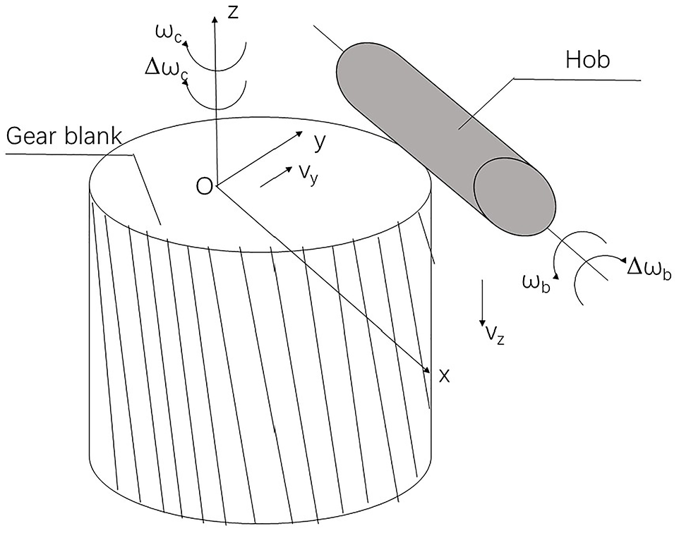
Schematic diagram of NC hobbing linkage control.
A cross-sectional end face gear blank shown in Figure 6. The hob is projected in the end face as the rack, and its knuckle line is tangent to the knuckle curve of the end face of the non-circular helical gear at point P. The pure rolling between the two requires the tooth blank to turn through the arc length s, and the projected rack moves through the distance l.
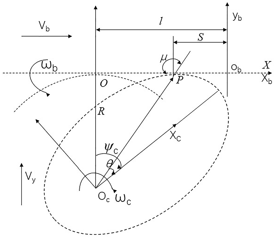
Gear blanks sectional projection.
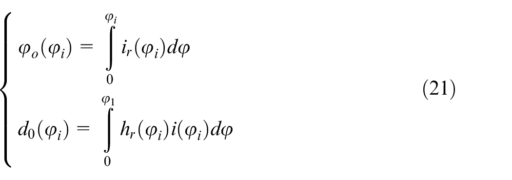
From Figure 6, it can be known from the calculus theory,
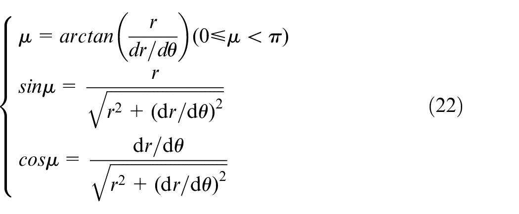
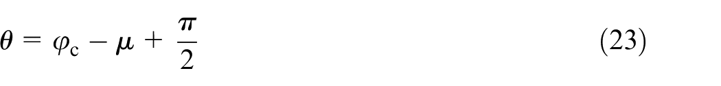
Where r is the polar diameter (mm), θ is the polar angle, μ is the radius cut angle.
Derivation of the formula (22)–(23),
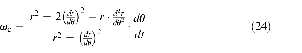
Where
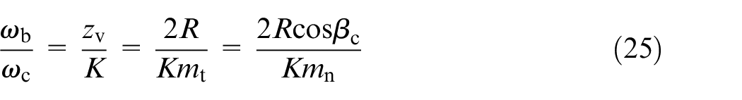
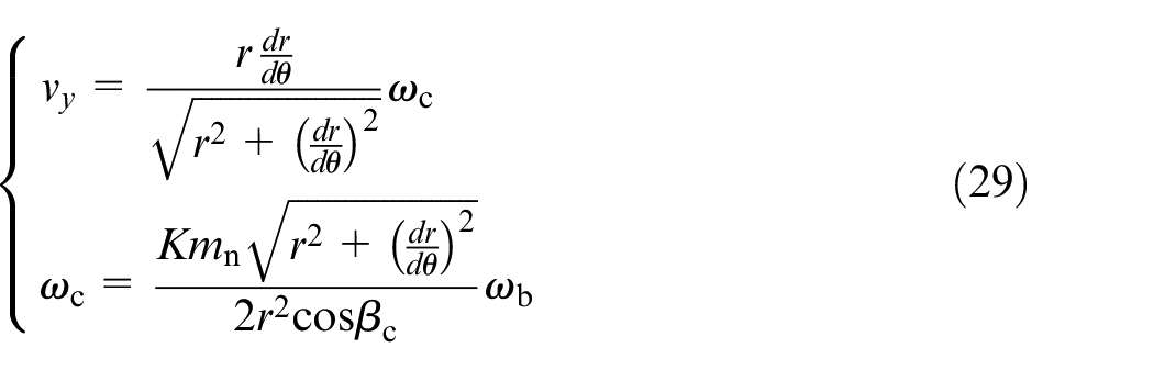
Since the nodal curve r = r(θ) is non-circular, ωc changes non-linearly with respect to ωb in the forming process. When the polar angle of the tooth blank is θ, there is a cylindrical helical equivalent gear with

Substituting formulas 22, 24, and 26 into 25, this study gets,
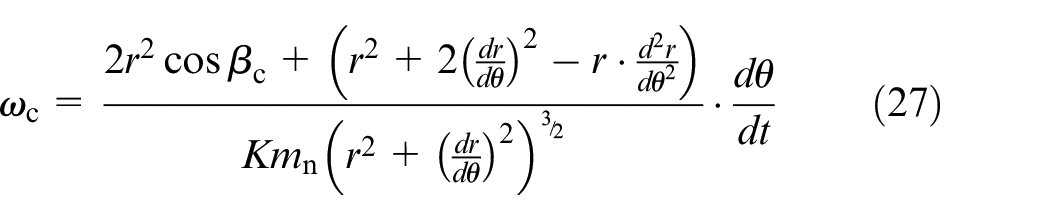
From the formula (27), there is the speed of the gear blank along the normal direction of the hob pitch line,
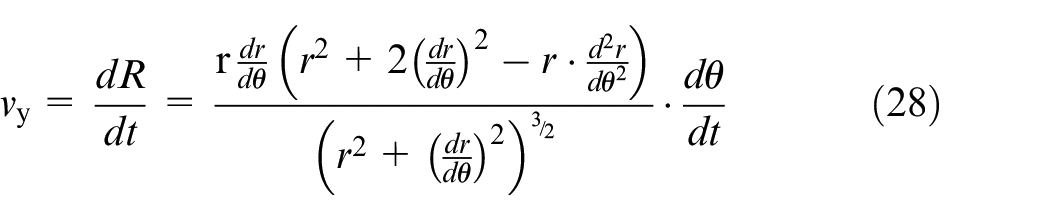
Synthesize the basic linkage model,
As shown in Figure 7, if there is an additional movement Δωc (labeled “A”) on the tooth blank, and one lead is moved along the axial direction of the tooth blank, the tooth blank rotates an additional revolution. Since the helix angle
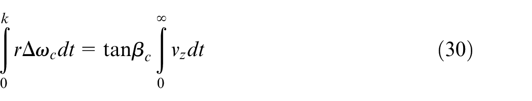
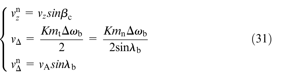
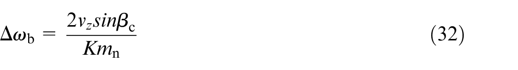
Where
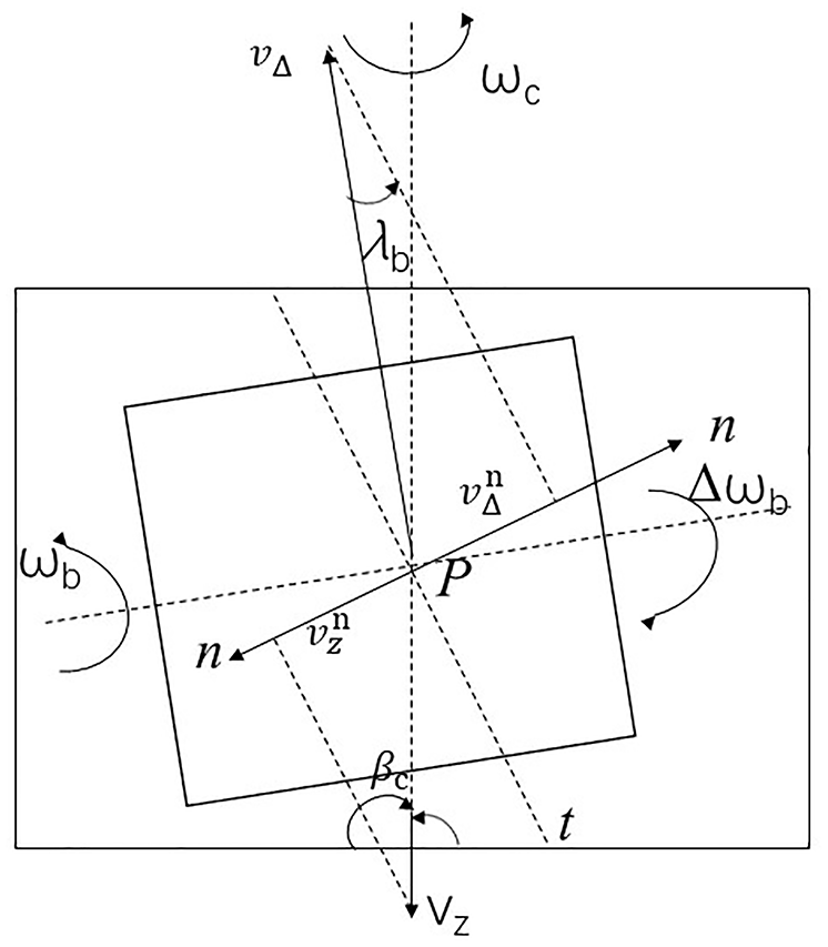
Schematic diagram of gear hobbing male section.
Processing of hobbing of helical non-circular gears
Through analyzing the machining process of helical non-circular gears and the secondary development of solidworks by programming software, the machining process of helical non-circular gears is simulated in a virtual environment, and the helical non-circular gears are modeled.17,18 The programming idea of using VB is to determine the corresponding horizontal and vertical distances of the helical rack, and reposition the coordinates of the helical rack every time the gear rotates through a certain angle. According to the set step length, up to the corner of the tooth blank. 19 It should be noted that a pair of correctly meshed helical non-circular gears have opposite generalized helix angles. Therefore, two rack cutters with equal generalized helix angles and opposite directions are required to envelop a pair of conjugated gears.
Programming with VB based on the principle of gear hobbing. 20 As shown in Figure 8, according to the different tooth profile positions, the discussion is divided into four situations. 21 Setting the arc length of the intersection point of tooth radius curvature and pitch curve to the intersection of the tooth profile and the pitch curve is s. Figure 8(a) shows the left tooth profile between the addendum line and the pitch curve. The mathematical model of the tooth profile curve is shown in equation (33); Figure 8(b) shows the left tooth profile between the tooth root line and the pitch curve. The mathematical model of the tooth profile curve is shown in equation (34); Figure 8(c) shows the right tooth profile between the tooth root line and the pitch curve. The mathematical model of the tooth profile curve is shown in equation (35); Figure 8(d) shows the right tooth profile between the addendum line and the pitch curve. The mathematical model of the tooth profile curve is shown in equation (36).
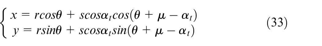
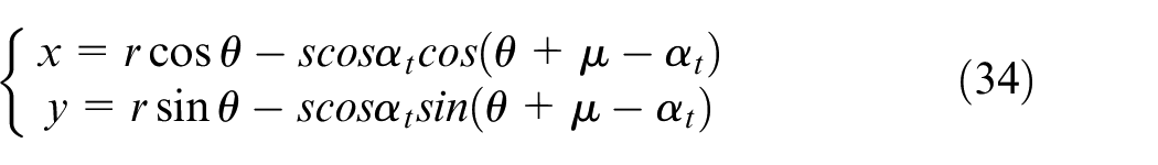

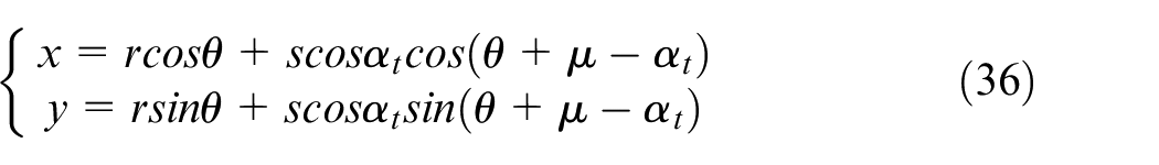
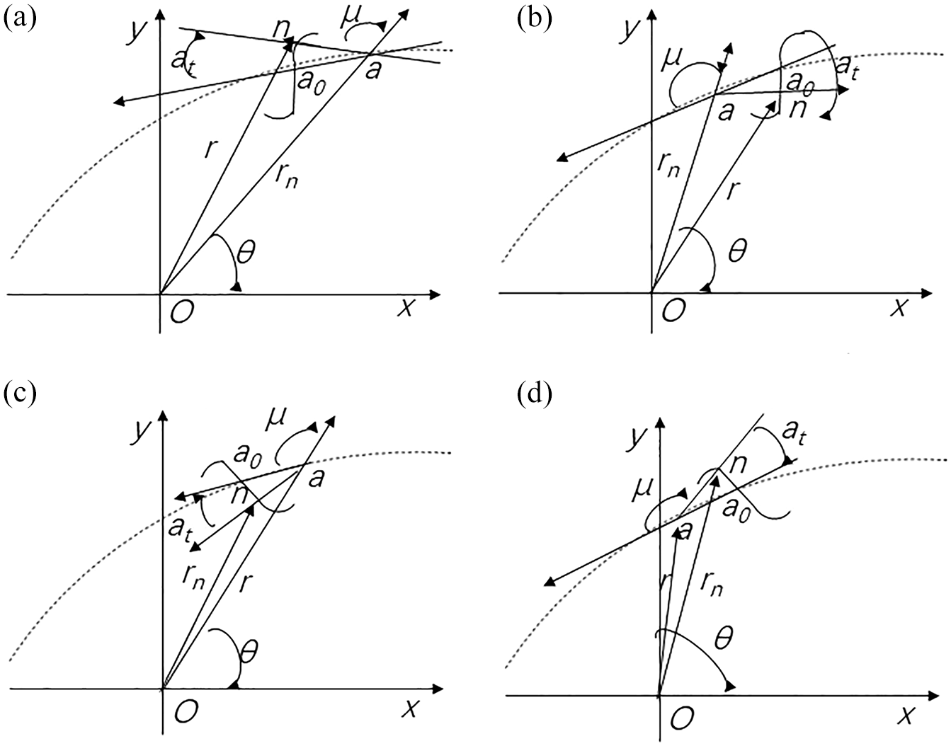
Non-circular gear tooth profile curve: (a) left contour between tooth top line and pitch curve, (b) left contour between tooth root line and pitch curve, (c) right contour between tooth root line and pitch curve, and (d) right contour between tooth top line and pitch curve.
In order to avoid the model reconstruction caused by cutting traces affecting the running speed of the software. In the analysis process, the 3D model of the helical gear and non-circular gear can be regenerated by coupling the midpoint of the cutting mark with the smooth curve. 22 Components need to consider the interference of different meshing positions.
For verifying the theory of non-circular gear hobbing in this article, this paper conducts an elliptical family of closed gear hobbing experiments on a self-developed CNC gear processing platform. In this paper, YN3610C6 CNC gear hobbing machine is selected for processing, the meshing point is moved at a constant speed and the diagonal rolling five-axis linkage scheme is adopted, and the flexible electronic gear box control technology is used to achieve the best linkage model. Hobbing a high-order multi-stage degeneration elliptical gear, the gear parameters are: A = 43.5294 mm, k1 = 0.15, n = 2, mn = 1 mm,
In the domain of x, the extreme diameter and extreme angle values of the corresponding points on the designed driving wheel pitch curve are sequentially extracted in an increasing sequence of 0.02, a total of 315 points. The results of fitting the driving wheel pitch curve with the piecewise cubic spline are as follows Table 1:
The segment coefficients of the segmented cubic spline fitting the driving wheel curve.
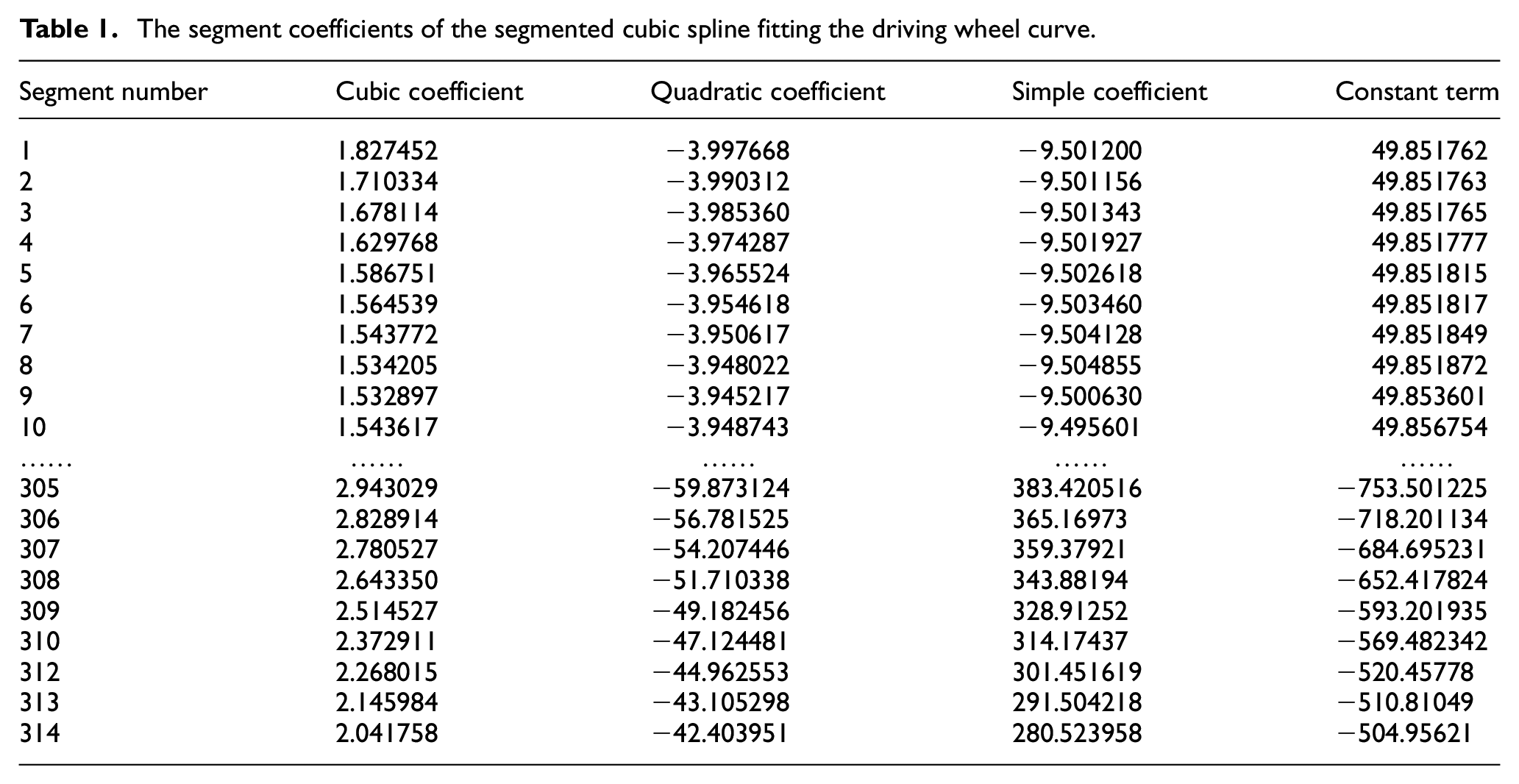
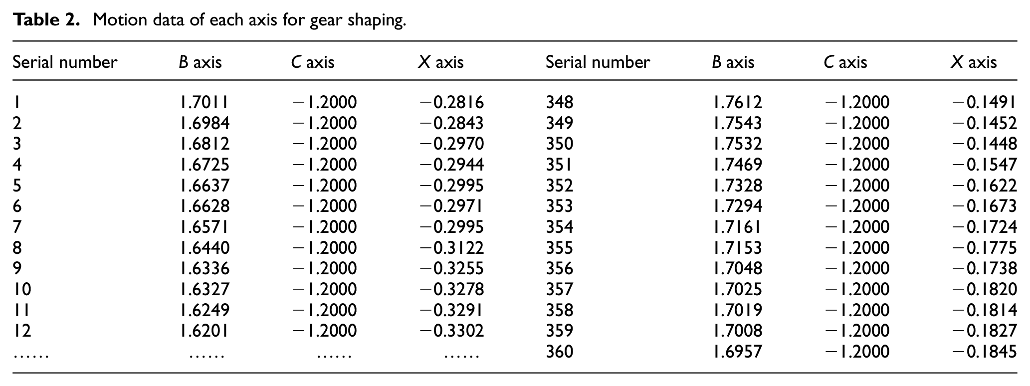
Taking the fitting coefficient segmented cubic spline of the pitch curve and the tooth blank rotation angle corresponding to the starting point of each segment as the look-up table array, import it into the gear shaping module in the system, and calculate the machining code for the generating motion of the slotting tool and the tooth blank in the gear shaping process. The machining accuracy of the driving wheel is 300 steps, and the number of steps to the full tooth depth is 60 steps, then 360 steps are required to complete all the tooth profile processing. The calculated driving wheel gear shaping processing data is as follows Table 2.
Motion data of each axis for gear shaping.
The process parameters are:
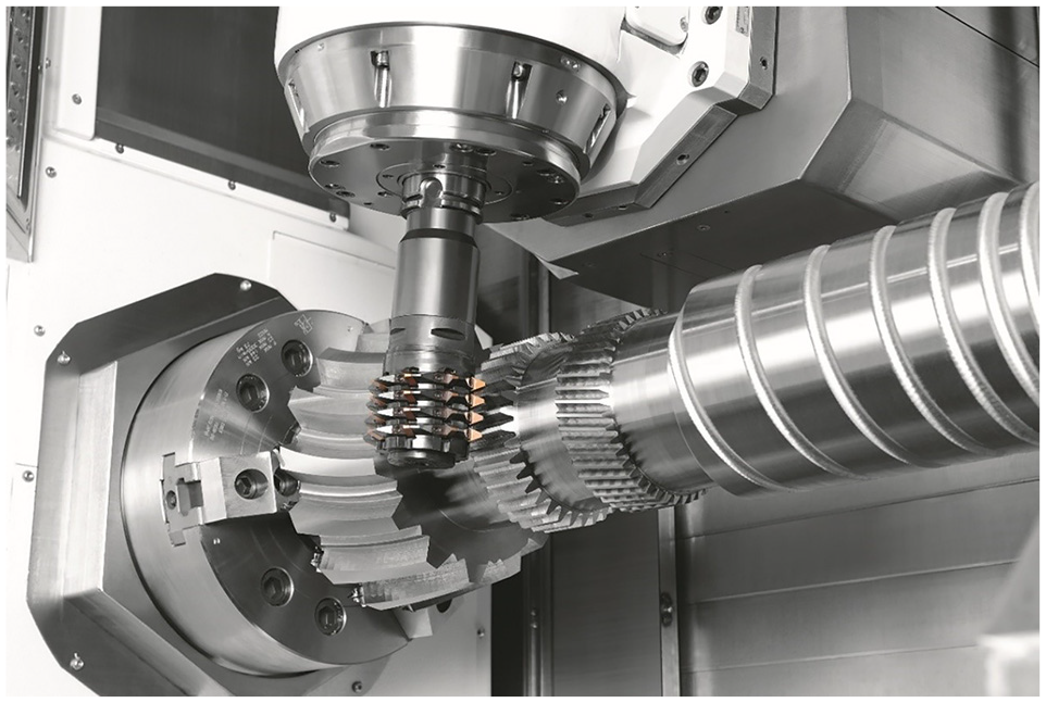
Hobbing process of high-order multi-segment modified elliptic gears.
Conclusion
This paper establishes the ellipse standard system for high-order non-circular gears, and puts forward the concept of gear transmission for the moving shaft (variable center distance and variable shaft angle) for the first time. This theory breaks through the shortcomings of the fixed relative positions of the driving and driven wheels in the traditional gear transmission mechanism. It is a gear transmission mechanism in a broader sense, which can realize the transmission of motion and force between relative moving components. On the other hand, this article provides a mathematical theoretical basis for the design and manufacture of non-circular gears. Aiming at the gear hobbing and gear shaping methods, based on the basic linkage model of non-circular gear CNC machining, this paper develops the realization method and model of non-circular gear (including the multi-stage modified round wheels), proposes linkage schemes and models to heighten the accuracy of gear machining and system control performance, and improves the theoretical system of rolling and inserting non-circular gears. For the first time, a computerized numerical control generation method based on moving shaft gear transmission was proposed, and a more applicable mathematical model of gear manufacturing linkage was established. This article expands the process range of the machine tool, improves the durability of the hob and the machining accuracy of the hobbing tooth surface, and realizes the hobbing of non-circular helical gears, and expanding the application range of non-circular gears. However, the research in this article has some limitations. This article does not conduct an in-depth discussion on the transmission performance of tooth surface. In the future, it will be conducted that thorough research on different tooth surface types from the perspective of providing gear transmission performance, such as contact strength, bending strength, and meshing stiffness. Moreover, the non-circular gear transmission proposed in this article is based on the making better gear theory. The transmission characteristics of these new forms of gears, such as contact marks and transmission errors, have not been discussed in depth. Subsequent research will conduct in-depth research on the meshing characteristics of the various new gear transmissions.
Footnotes
Appendix
Declaration of conflicting interests
The author(s) declared no potential conflicts of interest with respect to the research, authorship, and/or publication of this article.
Funding
The author(s) received no financial support for the research, authorship, and/or publication of this article.