
Abstract
Fiber reinforced composites, also referred as fiber reinforced plastics (FRPs) have gained considerable importance in engineering applications due to their unique qualities like high strength and stiffness at lesser weight, chemical inertness, thermal resistance, corrosion resistance, and electrical resistance. Though the machining of FRPs is not recommended, many times it is inevitable and the primary machining process like drilling is essential. This can cause delamination of the fibers thereby adversely affecting the mechanical properties of the composite and requires additional secondary finishing operation. The present investigation explores electrochemical discharge machining (ECDM) as a one of the novel technique to remove the delaminated fibers from such composites. Using ECDM the protruded delaminated fibers from a drilled hole in FRP have been precisely eliminated. Two different approaches viz. top machining and inside machining were followed for this purpose. Process evaluation was done in terms of its ability to remove the delaminated fibers and the extent of thermal damage (heat affected zone and hole overcut) to the workpiece. Both approaches have shown considerable potential of removal of delaminated fibers precisely.
Keywords
Objective addressed in the paper
Delaminated fibers occur after conventional drilling in a composite. To remove these delaminated fibers, electrochemical discharge machining (ECDM) is used as a secondary process.
Highlights: (major novel contributions)
Electrochemical discharge machining (ECDM) as an innovative method for removal of the delaminated fibers from a FRP product.
The effect of two different machining methods of ECDM viz. top and inside machining on heat affected zone (HAZ) and the hole overcut (HOC).
Influence of process parameters (voltage, feed rate, and tool rotation speed) on the HAZ and HOC.
Two different machining approaches suggested for removing delaminated fibers.
Introduction
Composite materials like fiber reinforced plastics (FRP) have higher strength-to-weight and modulus-to-weight ratios. They also provide opportunities for innovative product design and flexible manufacturing. Hence FRPs are finding extensive industrial applications in engineered products from automobile parts, sport goods, medical devices to aerospace industries. Ishikawa et al. 1 reported that European automotive manufactures recommend use of carbon fiber reinforced plastic (CFRP) in automotive structures. CFRP in automotive provides higher strength to weight and stiffness to weight ratios. Hatta et al. 2 studied the use of carbon-carbon (C/C) composites for space vehicles. The authors reported use of C/C composites for manufacturing the turbine disks, heat exchangers, and different components. To ensure structural integrity of such products, the primary machining operation like drilling needs to be performed. Due to the delamination of the fibers from the matrix, though such operations are not recommended, many times they are unavoidable. Konig and Graß 3 reported that the delamination during drilling is composed of damage of surface layer (referred as pitting) and improper cut of the composite layers (known as fuzzing). Tsao and Hocheng 4 reviewed that delamination of fibers is a serious defect that not only reduces the strength of the product but also adversely affects its dimensions and tolerances. It can also result in inferior long term performances of the product. Jin et al. 5 investigated drilling operation on CFRP composites. The authors concluded that torque and axial force exerted by the drilling tool are major factors causing delamination. Tsao 6 used core and core-saw drill to reduce the delamination of CFRP. The author revealed that the core-saw drill was more suitable than the core drill. It was observed that spindle speed and feed rate were the most influential factors on thrust force and delamination. They have also categorized the delamination into two types, viz. peel out and push out. Generally, peel out seen at the entrance of the hole and push out occurs at the exit. Tan et al. 7 investigated the delamination in hybrid carbon/ glass fiber reinforced polymer (HFRP) during drilling operation. The ratio of maximum diameter of damaged hole to the actual hole diameter was defined as “Delamination factor.” It was noticed that the delamination factor was 1.1–1.3 at the exit (push out) of the hole and 1.05–1.30 at an entrance (peel out) of the hole. Kumar et al. 8 studied the delamination during drilling of glass fiber reinforced polymer (GFRP) with different drills. The authors found that delamination factor changes with materials and geometry of the drill bit. Rajakumar et al. 9 reviewed the effect of drilling on CFRP composites. The authors summarized that the quality of the hole can be enhanced by low feeds and high spindle speeds. Shi et al. 10 reviewed the compound machining processes (ultrasonic-assisted mechanical machining and cutting-grinding compound machining) during drilling of CFRP and aramid fiber-reinforced polymer (AFRP). The authors found that burr (delaminated fibers) and tear defects are effectively controlled during the process. Geier et al. 11 studied unconventional technologies for drilling CFRP composites like electrical discharge machining (EDM), laser cutting, and water jet machining (WJM). The authors concluded the use of such techniques enhanced the machining time and cost of the process. Kumar and Singh 12 reviewed and presented a comparative study of conventional and unconventional drilling process for destruction free machining of CFRP and GFRP. The authors have emphasized the need of unconventional machining processes like EDM, laser beam machining (LBM), and rotary ultrasonic machining (RUM) for such composites. Hocheng and Tsao 13 concluded that it is difficult to completely avoid the delamination of fibers through the conventional drilling process. As an alternative they have explored unconventional drilling processes like; EDM, LBM, WJM, ultrasonic machining (UM), and electrochemical spark machining (ECSM). However, they have also found limitations in terms of materials applicability and process related factors like heat affected zone in such processes.
To remove the delaminated fibers from the drilled (primary machining) FRP products, an additional secondary finishing operation is thus required. Ning et al. 14 observed finishing operations based on the principles of erosion (like grinding) are not suitable as they may cause further delamination. Thus there exists a need to identify and study another technique for machining of such products. In this context, electrochemical discharge machining (ECDM) can be a promising technique to eliminate such fibers economically. It is based on controlled melting and vaporization to remove the delaminated fibers with very minimal subsurface damage.
ECDM is a hybrid machining process. It can be regarded as a combination of EDM and electrochemical machining (ECM). Yadav 15 reviewed the different machining variants of ECDM process like drilling, milling, sinking, dressing, grinding, turning, trepanning, and slicing. The author have presented an evolution of the ECDM process in last two decades and suggested future opportunities like vibration-assisted ECDM and magnetic-assisted ECDM. Singh and Singh 16 reviewed the capability of ECDM process; for machining conductive materials like steel, super-alloys as well as non-conductive materials like glass, ceramics, and composites. This is in contrast with EDM and ECM which can be used for only conductive materials. Jain et al. 17 identified the potential of ECSM process on composites. The authors successfully used ECSM process for drilling of Kevlar fiber epoxy and glass fiber epoxy composites. Jain et al. 18 also sliced Kevlar fiber epoxy and glass fiber epoxy composites using a traveling wire electrochemical spark machining (TW-ECSM). Liu et al. 19 performed wire electrochemical discharge machining (WECDM) and sliced particulate reinforced aluminum alloy 6061 (Al2O3). Liu et al. 20 removed the material using grinding-aided electrochemical discharge machining (G-ECDM) process on particulate reinforced aluminum alloy 6061 (Al2O3). Manna and Malik 21 sliced ceramic material (e-glass-fiber-epoxy) using wire electrochemical spark machining (WECSM). They found micro slicing has achieved using WECSM. Shamim et al. 22 successfully removed material and created a slit on Al6063/SiC/10p metal matrix composite using near dry wire electrochemical discharge machining (ND-WECDM). Similarly, Kumar et al. 23 sliced the SiC reinforced z-pinned composite using WECDM in micron.
Table 1 summarizes the application spectrum of ECDM explored by different researchers in machining of the composites. From Table 1, it is clear that the ECDM/ECSM process has only been used for micro-drilling, micro-slicing, and micro-grinding purposes. Also, Singh and Dvivedi 27 found that limited research reported on machining of composites with different machining variants of the ECDM.
Literature review of the composite material during ECDM process.
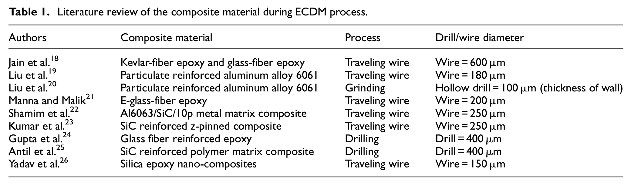
From the above literature, it is clear that there are no studies which report the application of ECDM for removing delaminated fibers. On the other hand, it can also be seen that ECDM has the potential to be used to address the delamination of fiber FRPs. This can be done by performing a secondary operation of removing delaminated fibers. The present study reports a novel approach to use ECDM process to remove micro delaminated fibers from the previously drilled holes in CFRPs. In order to achieve maximum accuracy and precision, two different orientations of the tool were used viz. top and inside machining. The effects of process parameters on the heat affected zone (HAZ) and the hole overcut (HOC) during the above machining methods also have been investigated.
Development of experimental setup
A customized experimental setup has been developed to conduct the present investigations and the schematic of which is shown in Figure 1.
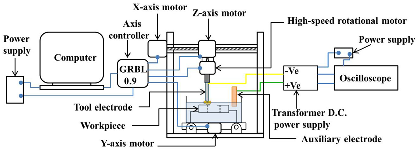
Schematic view of the experimental setup.
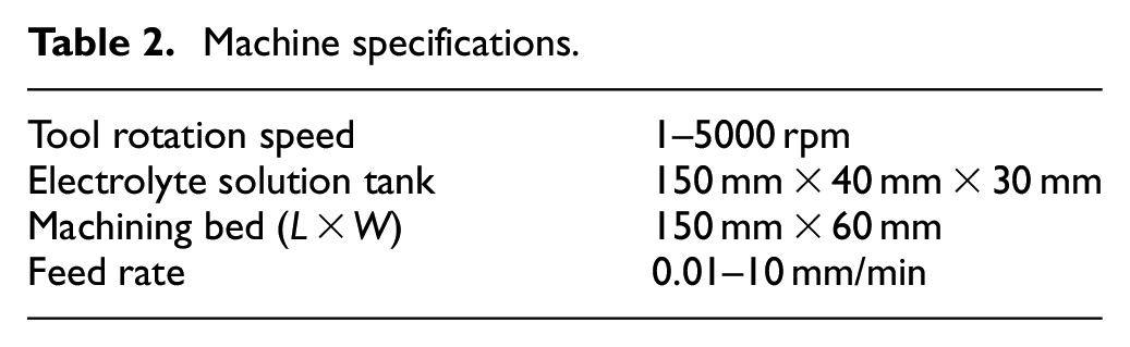
It consists of two electrodes viz. tool electrode (cathode) made up of tungsten carbide and the auxiliary electrode (anode) made up of copper which were submerged in an electrolytic solution of potassium hydroxide (KOH) in acrylic tank. A direct current (DC) power supply (10–110 V) was employed for the process. Workpiece fixtures were designed and fabricated to locate the drilled composite with delaminated fibers below the tool electrode. The dimension of the machining bed was 150 mm × 60mm. The movements of the tool electrode in X, Y, and Z directions were controlled using three stepper motors with a computer numerical control (CNC). A separate DC power supply (24 V, 10 A) was used for the smooth and accurate movement of these stepper motors. An oscilloscope was used to monitor the waveforms of different electrical signals with respect to time. The machine specifications are given in Table 2.
Machine specifications.
When a suitable potential difference is applied between the tool and the auxiliary electrode, the process of electrolysis begins. It affects the development of hydrogen bubbles at the tool and oxygen bubbles at the auxiliary electrode. These hydrogen bubbles form a gas layer in between tool tip and workpiece. When an appropriate voltage builds up and reaches the breakdown voltage (breakdown the gas film), causing a spark. 28 This spark results in the removal of delaminated fibers from the drilled hole. The experimental setup used for the study is shown in Figure 2. It also shows the spark generated during the process.
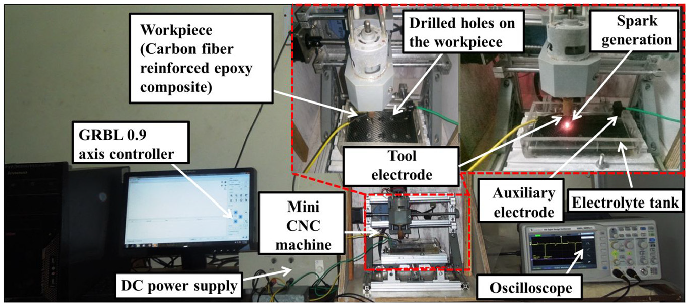
Pictorial view of the experimental setup.
Materials and methods
Preparation of workpiece material
A plate of carbon fiber reinforced epoxy composite with approximately 60% fibers by weight having a thickness of 3 mm was used as a workpiece in this study. It was prepared using conventional vacuum bagging technology. Bagging technology involves the use of a vacuum that potentially eliminates the blow holes in the composite. As a primary operation, this plate was drilled at a spindle speed of 1000 rpm using a twist drill of 4.8 mm diameter. Peel out type delaminated fiber at entry and push out type delaminated fiber at exit could be prominently seen as illustrated in Figures 3 and 4 respectively.
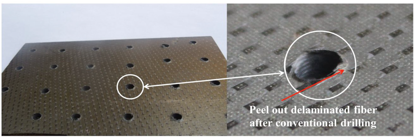
Peel out delamination at the entrance of the hole.
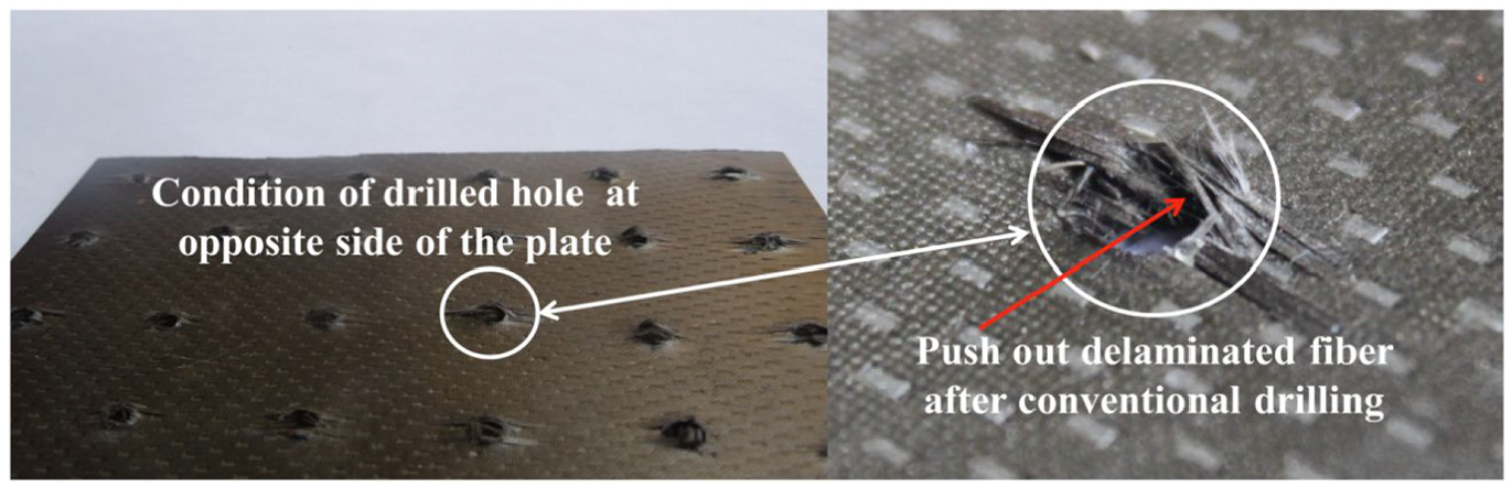
Push out delamination at an exit of the hole.
It was observed that push out type delamination had a significantly large number of loose fibers that adversely affect to the structural integrity of the product. Therefore a scanning electronic microscope (SEM) was used to characterize this region.
Figure 5 reveals the damage of surface layers at the exit of hole in the form of pitting, fuzzing, and tiny cracks in the last few layers of the material. It was found that the delaminated micro fibers near that region had an average length of 1.470 mm. Further, the SEM analysis indicated the average width of the fibers as 8.866 µm having a thickness of 3.481 µm. Such delamination causes considerable difficulty in the removal of fibers by using conventional machining processes like filing or grinding.
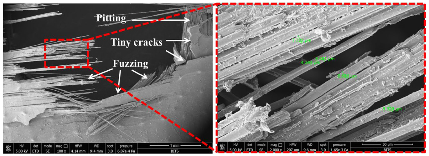
Loose fibers in push out delamination at exit of the hole.
Machining methods
Behroozfar and Razfar 29 showed that the thermal energy emission has more at the tool edges (a rim of the tool) and it can be used for removal of material. Based on this, a conical shape of tool and two machining methods viz. top machining and inside machining were used.
Figure 6(a) shows a technique to remove delaminated fibers from the top edge of the drilled hole and hence referred as “top machining.” During this operation, the loose push type reinforcements at the edges of the hole were removed by lateral travel of the tool on and around the face of the hole. Figure 6(b) shows the technique for removing the delaminated fibers from inside of the drilled hole and referred as “inside machining.” During this operation, rotation of the tool along the inner surface of hole was employed to remove delaminated fibers.
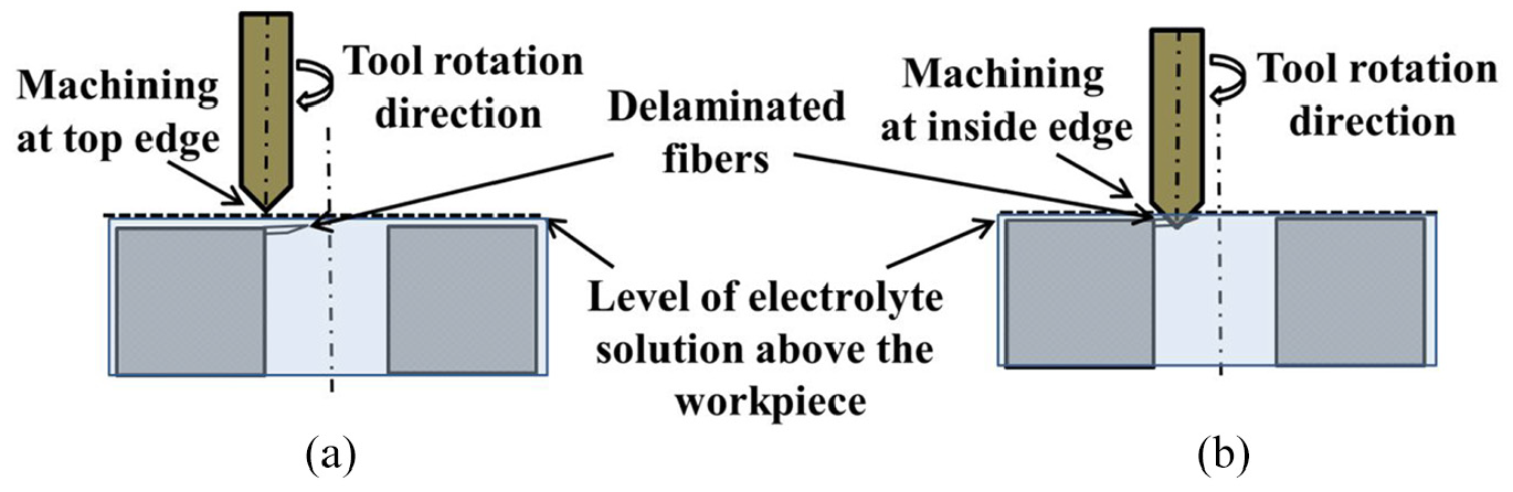
Machining methods (a) top machining and (b) inside machining.
Precise alignment of the tool and periphery of the hole were controlled by CNC controller (CNC-3018) in both approaches (top and inside machining). To achieve better alignment between tool tip and periphery of the hole, a fixture was designed inside the electrolyte tank. During both approaches, the micro fibers were removed by thermal energy emission of the rotating tool. Figure 7(a) and (b) further depicts the tool feeding for both, top and inside machining process respectively as discussed above. To ensure complete removal of protruded fibers, multiple passes of the tool over workpiece were employed.
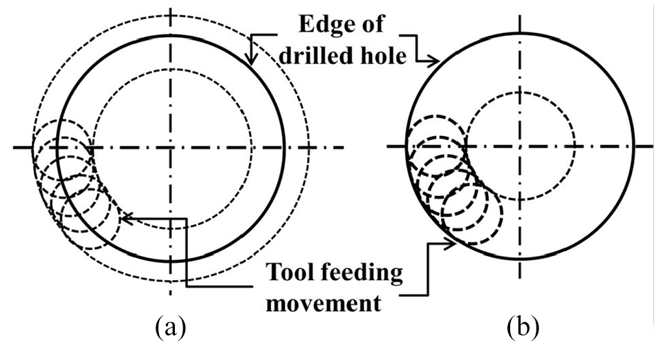
Tool feeding movement (a) top machining and (b) inside machining.
Regimes of process parameters
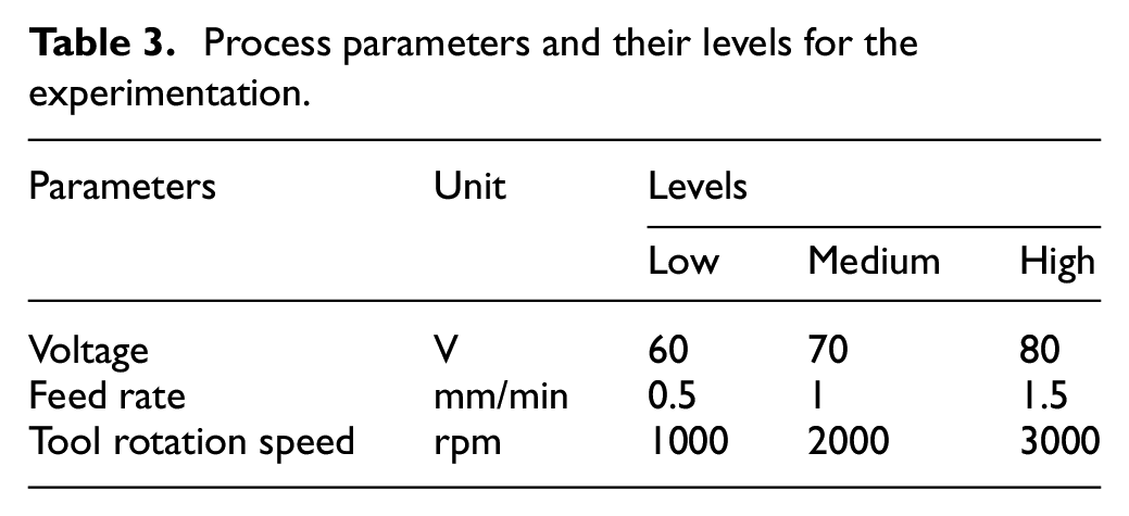
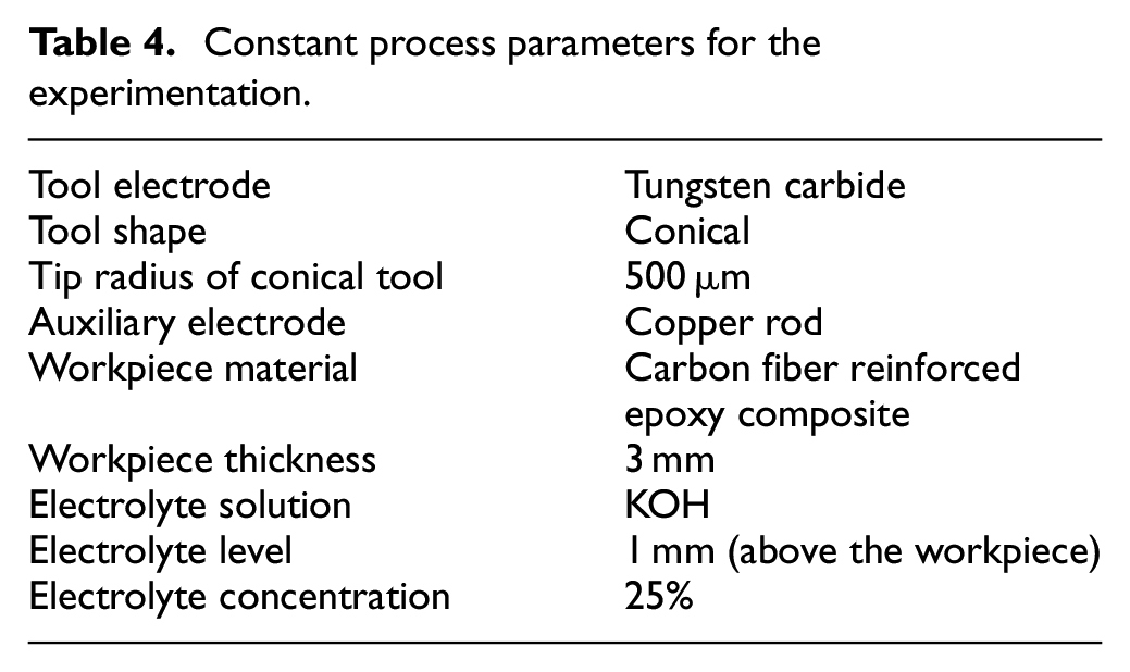
During the experimentation, it was found that performance of ECDM process gets affected by a number of process parameters. These can be categorized as electrical and non-electrical parameters. Electrical parameters include voltage, electrolytic concentration, current, and pulse duration while nonelectrical parameters can be an inter-electrode gap, feed rate, and tool rotation speed. Out of the “trivial many, vital few” parameters selected for the purpose of investigations were voltage, feed rate, and tool rotation speed. The performance of operation was investigated by two quality measures viz. HAZ and HOC. Levels of process parameters selected for the experimentation are listed in Table 3 while the parameters kept constant during the experimentation are given in Table 4.
Process parameters and their levels for the experimentation.
Constant process parameters for the experimentation.
The process parameters and their levels were selected based on the preliminary studies conducted as well as practical limitations of the present experimental set up. However, they are in tune with the existing literature in this field.
Measurements of HAZ and HOC
The thermal gradients during the process result in HAZ. To assess this, the average thickness of HAZ was measured with the help of SEM images. Figure 8(a) and (b) shows the schematic of this measurement for the top and inside machining respectively. It is represented in the form of concentric circles. The solid circle represents the drilled hole while the dotted circle represents the extent of HAZ. HAZ was estimated along the horizontal plane as the difference between the diameters of these circles.
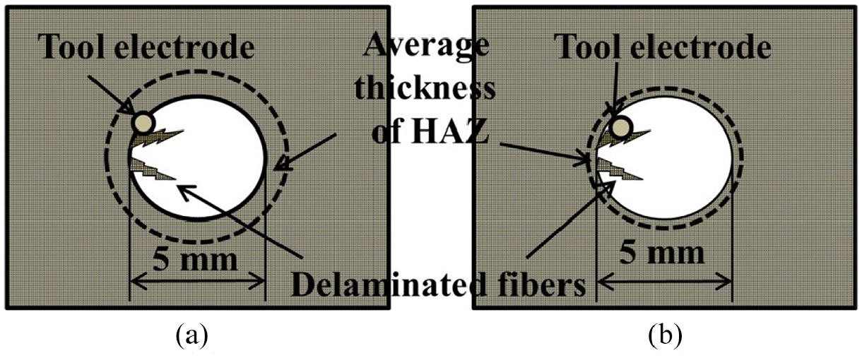
(a) HAZ in top machining and (b) HAZ in inside machining.
Apart from the HAZ, the thermal gradients may result in a slight increase (by a few microns) in the dimensions of drilled holes. This is referred as HOC. Figure 9(a) and (b) are used to illustrate the estimation of HOC during the process for a 5 mm diameter hole. The HOC can be observed as a slant surface as shown in Figure 9(a) and (b) for the top and inside machining respectively.
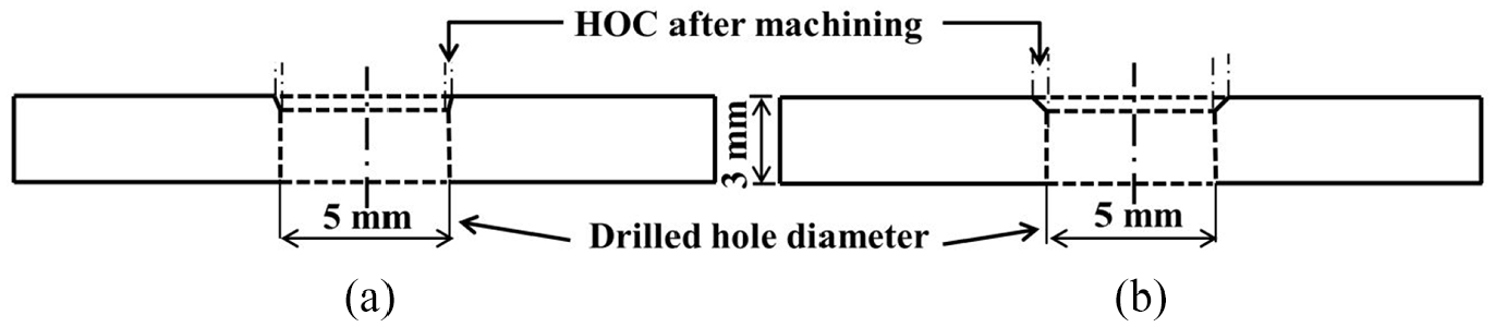
(a) HOC in top machining and (b) HOC in inside machining.
Results and discussion
Having carried out ECDM to remove the delaminated fibers of existing drilled holes, it was observed that the fibers were eliminated effectively with considerable ease and minimal subsurface damage. An account of the same is given in subsequent sections.
Comparison of top and inside machining for HAZ
Figures 10 and 11 show the SEM images of the HAZ, obtained after ECDM of the composite. The difference in the nature of HAZ which is formed during top and inside machining both can be perceived when comparing Figure 10 with Figure 11.
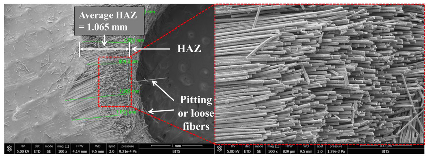
HAZ on the workpiece in top machining.
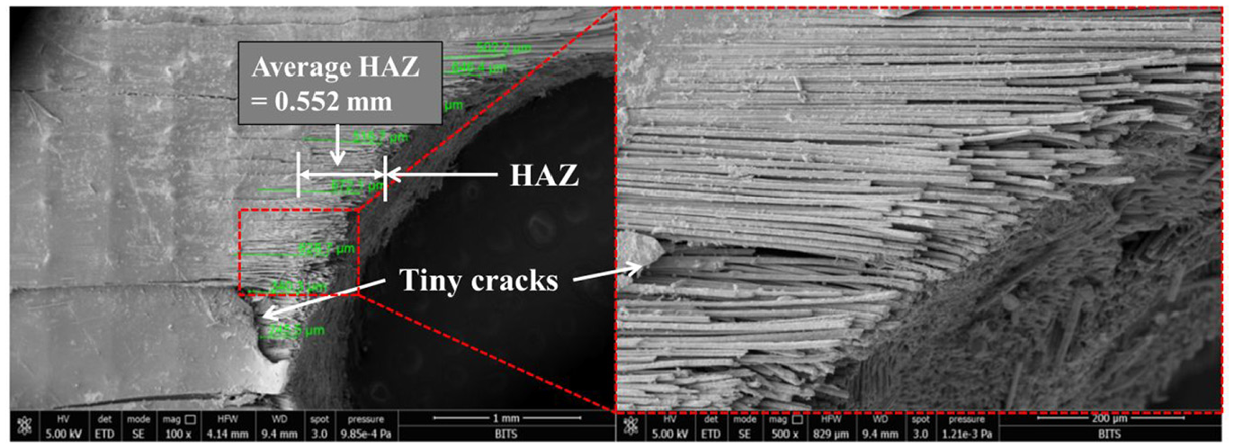
HAZ on the workpiece in inside machining.
Figure 10 shows that the loosening of fibers did not take place and the structure was uniform. It also did not reveal any particular pattern. It was also found that HAZ in top machining (Figure 10) was more than inside machining (Figure 11). This can be attributed to the proximity of the rotating tool with workpiece along the perimeter of the circle. It results in transfer of additional thermal energy on the top surface of the hole. However, when Figures 5 and 10 are compared, it is quite clear that the delaminated fibers were effectively removed during top machining. It was also observed that tiny cracks on the surface were also successfully removed.
The delaminated fibers present in the inner area of the hole were also effectively removed by the inside machining. This can be seen by comparing Figures 5 and 11. For inside machining, the perpendicular sides of the fibers are exposed to the heat source, which causes thermal damage near the removed fibers. Moreover, area available for conduction of heat is more for inside surface of the hole, resulting in less HAZ. It was also seen that pitting or loose fibers from the hole were effectively removed but some tiny cracks may result in case the thermal gradients are large. As the performance of the process is sensitive to the voltage, feed rate and tool rotation speed their effect was assessed on HAZ. It is depicted in Figure 12(a)−(c).
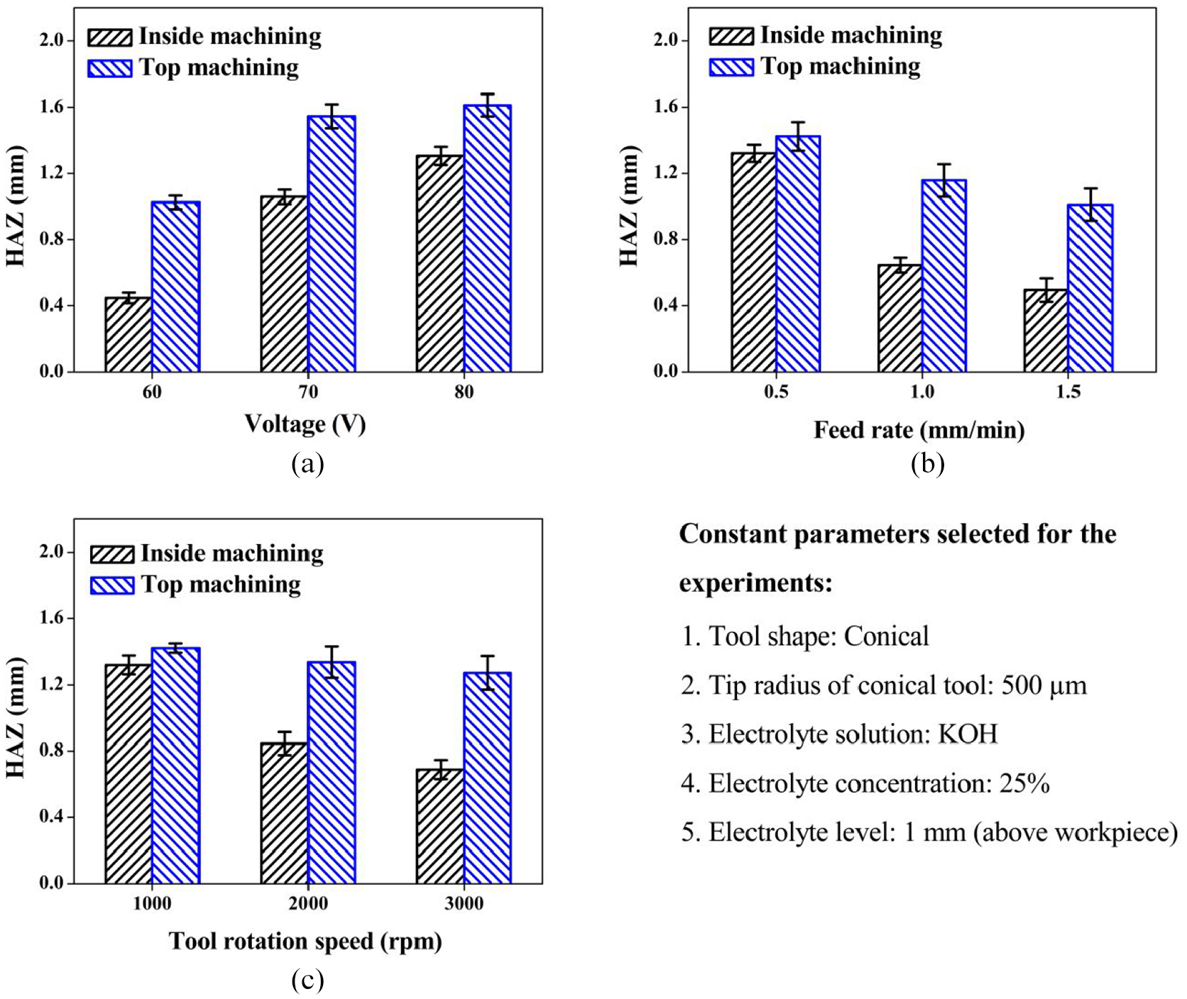
(a) Effect of voltage on HAZ, (b) effect of feed rate on HAZ, and (c) effect of tool rotation speed on HAZ.
From Figure 12(a), it can be seen that HAZ increases as voltage increases. According to Kim et al., 30 with increase in voltage, the rate of electrolysis increases, resulting in increase in the amount of hydrogen bubbles between tool tip and workpiece. Moreover, it was seen that discharge frequency increases with voltage which in turn increases the HAZ. Figure 12(a) shows, HAZ in top machining increased by from 1.025 to 1.611 mm at 60–80 V, whereas the HAZ in inside machining increased by 0.447–1.305 mm at 60–80 V.
Figure 12(b) shows that HAZ decreases with increased feed rate. This is in accordance with the observations by Ladeesh and Manu 31 that the feed rate of the tool decides the quantity of energy input to a particular region in the given time. Jain and Priyadarshini 32 also investigated that at a low feed rate, the contact time between machined surface and discharge is more resulting in an increase in the HAZ. From Figure 12(b), it was clear that the HAZ decreased by 1.423 mm to 1.011 mm in top machining and it decreased by 1.321–0.494 mm in inside machining at 0.5–1.5 mm/min respectively.
Figure 12(c) indicates that HAZ decreases with increasing tool rotation speed, probably due to the enhancement in the insulating capacity of the gas bubble layer between the tool electrode workpiece interfaces. Huang et al. 33 observed that the insulating ability of the gas bubble layer improves because of the centrifugal force during the rotation. This can potentially decrease the current density. Moreover, the heat dissipation capacity improves with higher rotational speed. It was also seen that with increased speed, the machining gap increases and therefore the thermal erosion is reduced. It can be seen from Figure 12(c) that the HAZ was reduced from 1.423 to 1.273 mm in top machining and it reduced from 1.321 to 0.689 mm in inside machining when the tool rotation was increased from 1000 to 3000 rpm respectively.
The comparison of HAZ in top and inside machining with respect to different process parameters is presented in Table 5. A total of 27 experiments were conducted according to 33 (General full factorial design) schemes of experiments on previously drilled holes. Each experiment was replicated thrice and the average values used to calculate the HAZ and HOC. From Table 5, it is clear that top and inside machining when performed at 60 V, 1.5 mm/min, and 1000 rpm produces the best results in terms of minimized in the form of minimal HAZ.
Comparison of HAZ and HOC for top and inside machining.
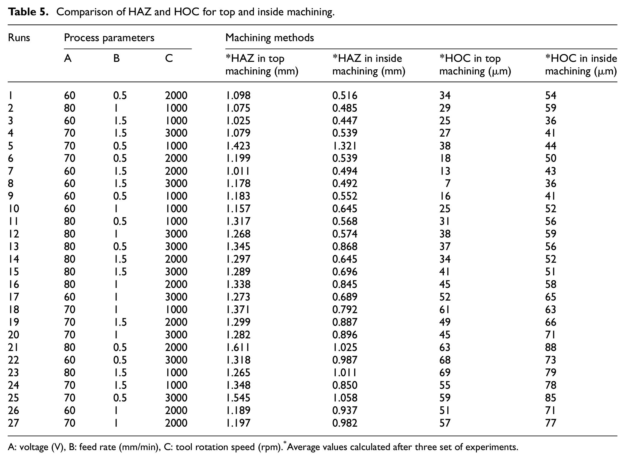
A: voltage (V), B: feed rate (mm/min), C: tool rotation speed (rpm).
Average values calculated after three set of experiments.
Comparison of top and inside machining for HOC
While comparing the HOC in top machining with that of inside machining, it was found that HOC was comparatively lower in top machining (5.007 mm) than inside machining (5.036 mm) which is shown in Figure 13(a) and (b).
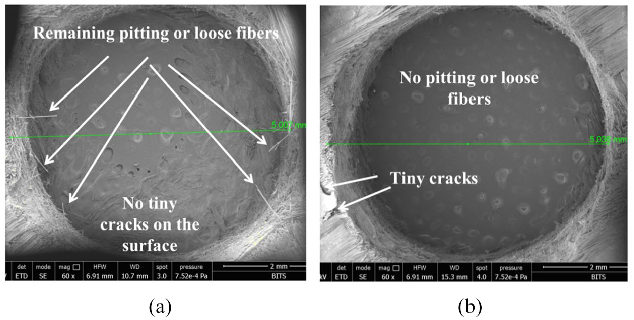
(a) HOC in top machining and (b) HOC in inside machining.
By comparing Figure 13(a) and (b) with Figure 5, it was observed that machining defects like tiny cracks and pitting or loose fibers occurred during conventional drilling (primary operation) were successfully removed. During inside machining (Figure 13(b)), a small amount of material was also removed which has resulted in an increase in HOC. The effect of process parameters on HOC was assessed. Figure 14(a)−(c) shows that the effect of voltage, feed rate, and tool rotation speed on HOC.
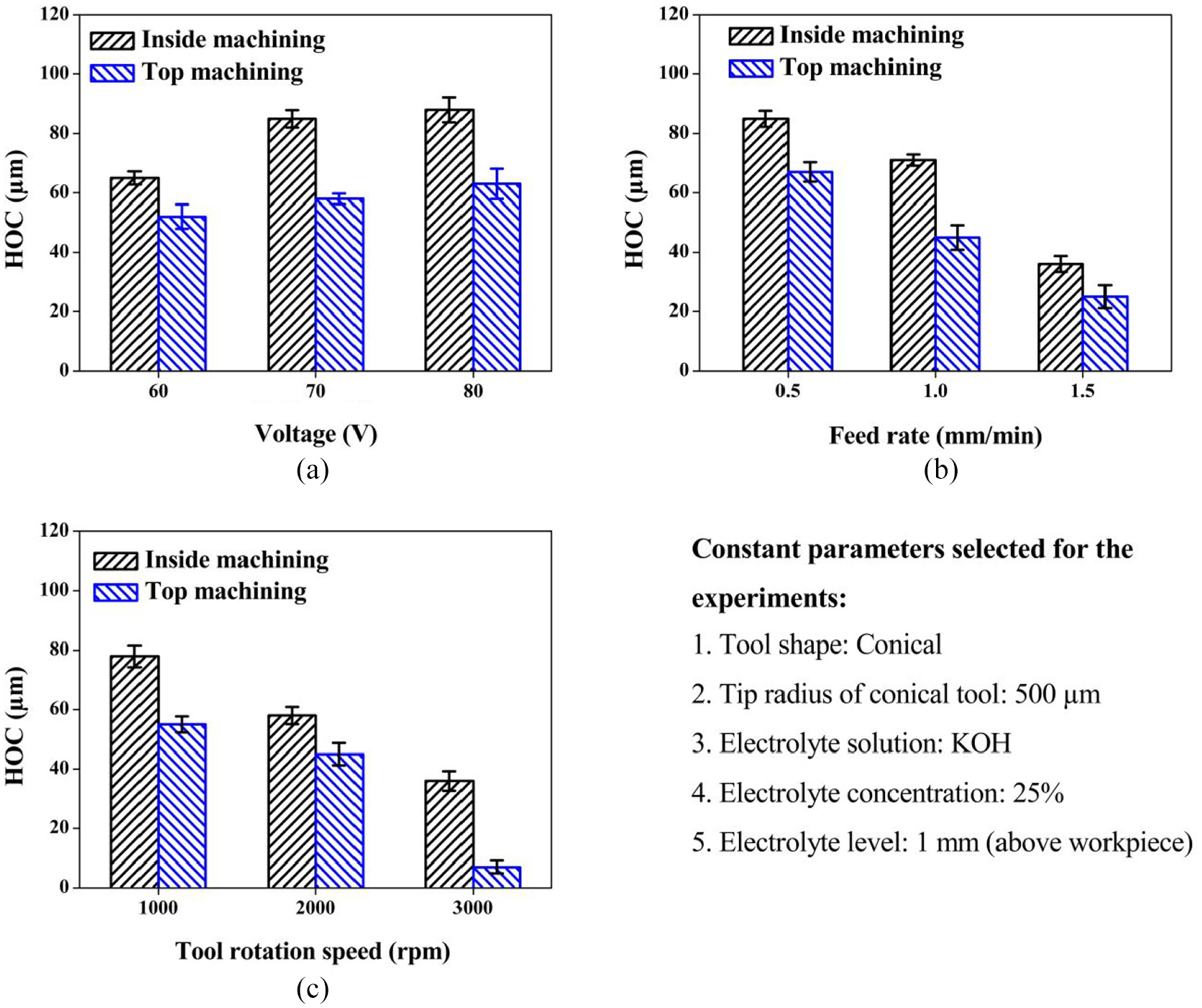
(a) Effect of voltage on HOC, (b) effect of feed rate on HOC, and (c) effect of tool rotation speed on HOC.
The effect of voltage on HOC can be observed in Figure 14(a). HOC progressively increases with the increase of voltage. Arya and Dvivedi 34 found that gas film generates at the discharge zone (in this case, between tool edge and the edge of drilled hole) at high voltage. Bhattacharyya et al. 35 have also shown that the gas film causes higher breakdown of voltage and more thermal energy available for erosion, resulting in increase of material removal (in this case, material removed at the edge of the drilled hole). It was observed that HOC increased with increasing voltage (60–80 V); 52–63 µm in top machining and 65–88 µm in inside machining.
Figure 14(b) shows that the effect of tool feed rate on HOC of the workpiece. It was observed that HOC decreases with an increase in the feed rate. Arab et al. 36 observed that uniform and steady thermal discharge at lower feed rate enhances over cut. Also, Goud and Sharma 37 applied different feed rates and investigated that, at the lower feed rate the time available for thermal erosion increases. From Figure 14(b) it was observed that HOC reduced from 67 to 25 µm in top machining and it reduced from 85 to 36 µm in inside machining at 0.5–1.5 mm/min respectively.
From Figure 14(c), it was observed that HOC reduced with increased tool rotation speed. Liu et al. 38 identified the reason of reduction in HOC. They have found that stable gas bubble creation is difficult in high tool rotation speed and unstable gas bubbles deteriorate discharge conditions. The unstable gas bubbles are formed due to the centrifugal force generated by the tool. So in these conditions, deteriorated thermal discharge removes less base material from the edge of the hole. From the Figure 14(c) it was clear that, when tool rotation speed increased from 1000 to 3000 rpm, HOC was decreased 55–7 µm in top machining and 78–36 µm in inside machining.
Comparison of HOC in top and inside machining is presented in Table 5. It was observed that the HOC was higher in inside machining compared to the top machining in all the variants of the process parameters. It was observed that when the top and inside machining performed at 60 V, 1.5 mm/min, and 3000 rpm produces the best result in terms of a minimized form of HOC.
Conclusions
Conventional machining of reinforced composite material causes delaminated fibers on the machined surface. This can result in the weak structure as well as a rough surface finish and therefore requires a secondary treatment. In this study, an attempt has been made to use the ECDM process as an unconventional process for removing delaminated fibers of carbon fiber reinforced epoxy composite. Two different approaches viz. top and inside machining were investigated and it was found that both were effective during the machining process with a few limitations mainly due to the inherent process characteristics. The important observations can be summarized as:
ECDM can be successfully used for removing delaminated fibers of the CFRP composite. This was demonstrated by developing an in-house set up of the process.
Surface characterization using SEM images showed that in top machining, delaminated fibers around the hole were removed. For the inside machining also, delaminated fibers around and inside of the hole were completely removed. Thus, this method results in the generation of a high quality machined surface.
In both methods, voltage and feed rate were seen as the most important process parameters. The study shows that increase in voltage (60–80 V) increases HAZ and HOC; increase in feed rate (0.5–1.5 mm/min) reduces the HAZ and HOC. Also, increase in tool rotation speed (1000–3000 rpm) reduces HAZ and HOC.
The combination of machining parameters, that is, applied voltage 60 V, feed rate 1.5 mm/min, and tool rotation speed 1000 rpm shows minimum HAZ of 1.025 and 0.447 mm at the top and inside machining respectively.
On the other hand, combination of applied voltage 60 V, feed rate 1.5 mm/min, and tool rotation speed 3000 rpm shows minimum HOC of 7 and 36 µm at the top and inside machining respectively.
With the development of further control over the spark energy generated, the damage can be minimized and use this process as a cost-effective tool for the post-processing of laminated composites without affecting their structural integrity.
Footnotes
Acknowledgements
The authors gratefully acknowledge the support of center for sophisticated instrumentation facility (CSIF), BITS Pilani, K. K. Birla Goa campus, for facilitating the SEM analysis for this research.
Declaration of conflicting interests
The author(s) declared no potential conflicts of interest with respect to the research, authorship, and/or publication of this article.
Funding
The author(s) received no financial support for the research, authorship, and/or publication of this article.
Supplemental material
Supplemental material for this article is available online.
References
Supplementary Material
Please find the following supplemental material available below.
For Open Access articles published under a Creative Commons License, all supplemental material carries the same license as the article it is associated with.
For non-Open Access articles published, all supplemental material carries a non-exclusive license, and permission requests for re-use of supplemental material or any part of supplemental material shall be sent directly to the copyright owner as specified in the copyright notice associated with the article.