
Abstract
The adoption of Industry 4.0 technologies within the manufacturing and process industries is widely accepted to have benefits for production cycles, increase system flexibility and give production managers more options on the production line through reconfigurable systems. A key enabler in Industry 4.0 technology is the rise in Cyber-Physical Systems (CPS) and Digital Twins (DTs). Both technologies connect the physical to the cyber world in order to generate smart manufacturing capabilities. State of the art research accurately describes the frameworks, challenges and advantages surrounding these technologies but fails to deliver on testbeds and case studies that can be used for development and validation. This research demonstrates a novel proof of concept Industry 4.0 production system which lays the foundations for future research in DT technologies, process optimisation and manufacturing data analytics. Using a connected system of commercial off-the-shelf cameras to retrofit a standard programmable logic controlled production process, a digital simulation is updated in real time to create the DT. The system can identify and accurately track the product through the production cycle whilst updating the DT in real-time. The implemented system is a lightweight, low cost, customable and scalable design solution which provides a testbed for practical Industry 4.0 research both for academic and industrial research purposes.
Keywords
Introduction
Manufacturing systems are dramatically changing as a result of the Fourth Industrial Revolution (IR4.0) and the increase in the digitisation of the manufacturing industry.1,2 Global competitiveness has amplified the need for manufacturers to be reactive and adaptive to increasingly diverse customer demands and on much shorter time scales than ever before. These factors lead to increased complexity and a reduction in decision time within the manufacturing system, both of which require intelligent and innovative technologies.
Two such technologies that are addressing these manufacturing challenges are the CPS3–5 and the DT.6,7 Each have similar attributes such that they seek to connect the physical with the cyber world using a variety of communication methods. A CPS focuses on the interaction between the two worlds whereas the DT provides a complete digital description of the physical process. Each can consist of interconnected sensors and communication networks which may include cloud and/or edge computing.8–10
A DT is a digital representation of a physical asset. The degree of complexity of the DT, which can be a realtime or predictive representation a system, is specific to the intended use of the DT. DTs can represent different types of system behaviour and levels of complexity within the system depending on the user requirements.11,12 They can be applied to all stages in the product lifecycle from prototyping through to production. Specific to the manufacturing industry, when a DT and CPS is deployed into production environment it is termed a Cyber-Physical Production system (CPPS).
The digitisation of the shop floor has ensured more accurate and timely information flows which has improved reporting times, reduced reporting errors and aided process planning flexibility. The secondary benefit of digitisation has been the availability of data for Prognostic and Health Management (PHM) applications. In a modern production process there exists a need for integration between the factory floor automation level and the Enterprise Resource Planning (ERP) level. Interfacing between these two levels is the Manufacturing Execution System (MES) and the function of the MES to control production lines in order to meet the business strategy.13,14 The MES provides a required level of situational awareness of the production process and in order to improve the fidelity and accuracy of the system a CPPS is required. The CPPS can be both real-time, to assist time-critical decision making, and also predictive to enable planners off-line solutions to on-line problems thereby removing any unnecessary costs of plant downtime. 15 With an ever increasing and complex set of requirements for the factory of the future there is a requirement for a DT and CPPS to operate in real-time. The production managers and operators then have the ability to view the whole production system from the unit level through to the operational level and have complete visibility of the operating capacity, overall equipment effectiveness (OEE) and full control of the ERP.
An integral component of a CPS is Machine to Machine communication (M2M). M2M includes any communication between machines, controllers and actuators using both wired and wireless networks. M2M is a key part of Internet of Things (IoT) networks and there is a host of commercial and open-source protocols which have been designed for the manufacturing sector. 16 MTConnect and OPC-Unified Architecture (OPC-UA) are two communication protocols specifically designed for industrial automation.17,18 MTConnect has been designed towards the Computer Numerical Control (CNC) machine shop with predefined data structures and rules whereas OPC-UA provides a more open user-defined variable structure which results in a wider scope of implementation. 19 OPC-UA has the capability to both receive and send information where MTConnect can only monitor. The use of OPC-UA has been an enabling technology in this research.
The challenge within the CPS context is to use the available data in a smart manner to improve productivity, accurately predict system response and reduce system downtime. 20 Therefore, the same information that is used to update the MES (PLC and M2M data) can be used to update the DT. One source of real-time data is programmable logic controller (PLC). 21 Significant process data can be accessed from the PLC such as counters for throughput metrics or from radio-frequency identification (RFID).22–24 tags on pallets. Pallets are load carrying components of a production line that transport the product around the plant during the various phases of production. The RFID tags contain electronically stored information and use electromagnetic fields to enable automatic identification and tracking whilst attached to objects. The RFID tags located in the pallets can be read by RFID sensors at strategic points around the production system. The use of RFID tags to assist tracking in manufacturing assembly lines has been a proven capability for many years.25,26 Placing RFID sensors at strategic locations around a manufacturing plant, such as at stations and loading/unloading platforms, then the MES can be kept up-to-date with the state of the production plant. The data from RFID tags can be sent to the MES either via PLC communication or through one of the many M2M communication methods. When RFID object detection is set far at a distance from the sensor then signal strength can lead to difficulty in detection therefore methods have combined RFID with computer vision techniques27,28 to improve detection and tracking. The technologies described above (RFID, PLC, Fast M2M communications) are all key components to a successful CPPS and DT.
It has been demonstrated that conducting research on teaching platforms can aid development of Industry 4.0 technologies. A detailed review of manufacturing and production testbeds for teaching and research is presented in Abele et al. 29 The research highlighted that many legacy testbeds were designed for a specific manufacturing teaching goal. Many testbeds were designed to teach production principles pre-Industry 4.0, therefore, there is now a shift to develop demonstrators for smart manufacturing 30 and Industry 4.0 technologies. Some examples are now discussed.
The iFactory, housed with the Intelligent Manufacturing Systems 31 Center at Windsor, Canada is a reconfigurable manufacturing plant focused on systems learning, re-configurable processes and product design and customisation. The Experimental and Digital Factory 32 at the Chemnitz University of Technology consists of networked laboratories used for teaching various aspects of manufacturing processes. The Smart Factory KL 33 at the Technical University of Kaiserslautern consists of a testbed with many of the key communication technologies used within this research such as RFID and networked systems. The facility demonstrates a liquid soap manufacturing system. The Smart Factory, 34 at the Fraunhofer Project Center at MTA SZATKI in Hungary, is a compact production facility which explores physical and virtual manufacturing processes. The Smart Production Laboratory (Smart Lab) 35 at Aalborg University consists of reconfigurable cells interconnected with conveyor systems with research focused on emerging digital technologies such as virtual commissioning. Both the MTA SZATKI and Aalborg plants initially focused research on the cyber physical production system and both will subsequently benefit from applied digital twin research. Other similar modular systems include I4.0 Lab 36 at Politecnico di Milano, SmartPro4.0 37 at Zurich University of Applied Sciences, Swiss Smart Factory 38 at the Switzerland Innovation Park, Bern and the Industry 4.0 Pilot Factory (I40PF) 39 at the Technical University of Vienna. These centres all offer a multitude of smart manufacturing capabilities but have yet to take the CPPS or Digital Twin research to publication. And finally, in terms of production line tracking, a computer integrated manufacturing scenario 40 implemented a vision based tracking system to a production line teaching demonstrator which resulted in position updates every 25 s to a cloud based system for visualisation.
Few studies have demonstrated the implementation of a real-time production DT for Industry 4.0 research. There is a need for practical research testbeds to demonstrate and publish future technologies for the manufacturing sector. This includes research for the factory of the future and for the transition of legacy factories to become IR4.0 capable. Ribeirio and Bjorkman 41 described the challenges from transitioning from a standard automation system to a CPPS and Uhleman et al. 42 highlighted the need for scalable demonstrator platforms to demonstrate the IR4.0 principles where the requirements included the need for real-time data acquisition to support DTs.
There exists a gap in research demonstrating production digital twin capable testbeds. The platforms are required to develop and validate future practical industry 4.0 technology and research, moving away from the theoretical structures and frameworks described in literature and providing tangible results based research outputs.
In this paper the authors demonstrate a proof of concept implementation which fills that gap in the research in order to provide a testbed for further academic and industrial research. Intended research applications include digital twin research, production process optimisation and manufacturing data analytics.
Paper organisation This paper is organised as follows, first, the physical description of the CPPS lab is described, second, the development of the DT model is presented, third, the development of the vision tracking system is presented and finally the results of the system implementation are discussed.
Cyber physical production system
CPPS description
The CPPS Lab, housed at the University of Sheffield, is a modular Industry 4.0 learning system from FESTO Didactic. The system is representative of a modern industrial production line which is fitted with the capabilities to demonstrate and communicate with Industry 4.0 methodologies and standards. Figure 1 shows the key components defined within automation level framework. The production factory consists of many work stations interconnected by conveyor transport systems. The CPPS Lab consists of a remote PC terminal, two work stations and a pallet carrying robot station named Robotino. The physical system layout is divided into two work stations (as shown in Figure 2). Each work station consists of four hardware modules which are further broken down into three application modules and one bridge pallet transfer module. The four modules are connected in a loop configuration as shown in Figure 3. The pallet can be loaded or unloaded from each work station using the bridge pallet transfer module. The Robotino carries the pallets between the two bridge pallet transfer modules which act as docking stations.
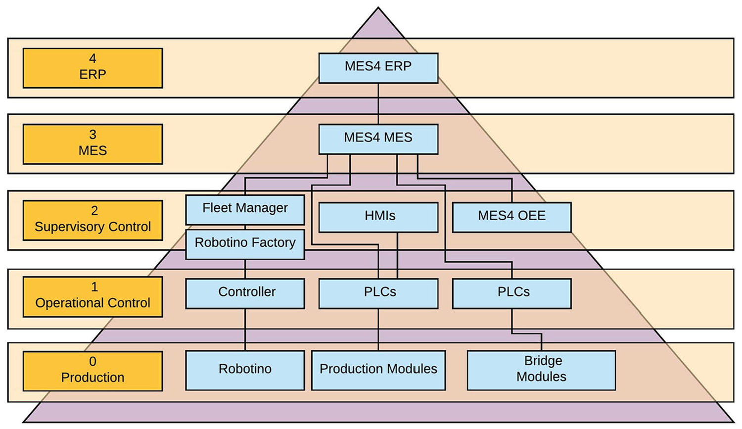
Automation level framework showing the key components of the cyber physical production system laboratory.
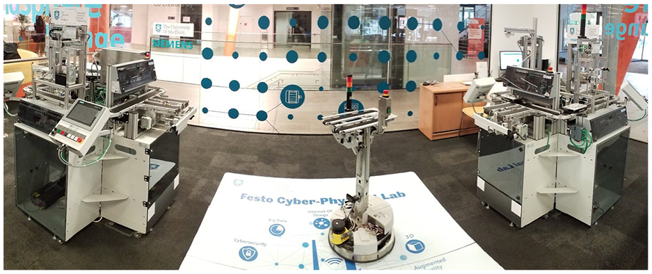
The cyber physical production system laboratory (University of Sheffield, UK).
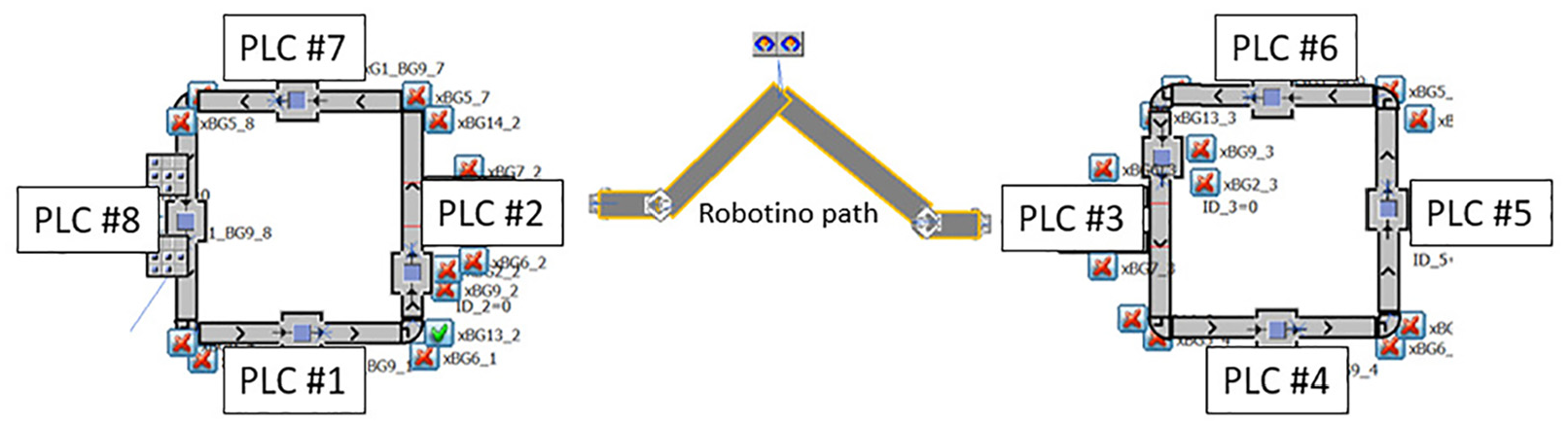
Station and PLC configuration.
The six application modules each represent a part of a standard industrial manufacturing process. The specific function of the CPPS Lab is a mobile phone production line where upper and lower panels of a mobile phone case are joined together and heat treated before being removed from the conveyor system for unloading. Numbered pallets move around the production line; stopping at each station to carry out the respective function. Each pallet contains an RFID chip that is read by sensors situated at each station for pallet identification. The application modules consist of the following functions (in order) – Magazine application (front panel), height measuring module, magazine application (back panel), pneumatic press, tunnel heater and finally an output module for physical removal from the production line.
All eight modules consist of a pallet carrying conveyor system, a series of sensors (including an RFID sensor), a PLC and in-built OPC-UA servers as shown in Figure 4. The layout is shown in Figure 3. The application modules are controlled by Siemens S7 ET200SP PLCs with Siemens TP700 touch panel human machine interfaces (HMIs). The PLCs are each connected to a PROFINET via RJ45 connections. The PROFINET communicates with the local PC which hosts the MES via an OPC-UA server for production orders, system status and maintenance functions. The two bridge modules are controlled by FESTO PLCs using CoDeSys software connected to the local PC via an OPC-UA server. UA Expert was used as an OPC-UA client during system testing and for monitoring purposes.
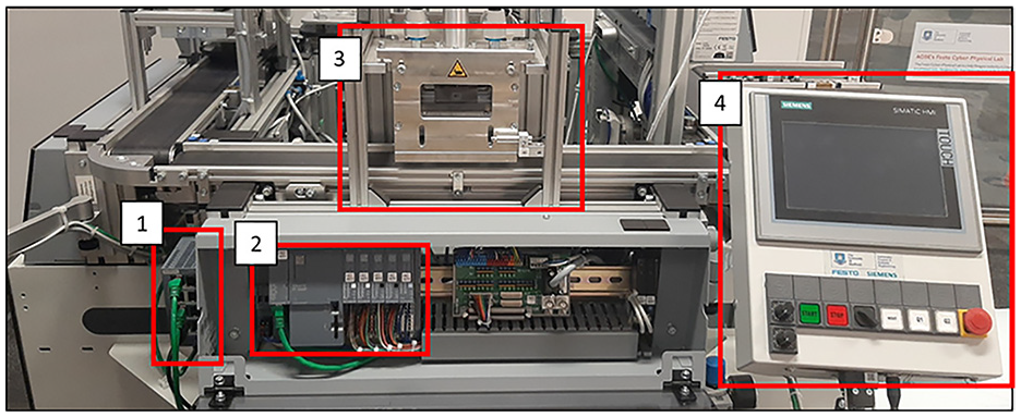
Standard process module components: PROFINET (LAN connection) (1), PLC (2) (which houses the OPC-UA server), process module (3) and HMI (4).
Digital twin
Within this research, the DT is termed a ‘Simulation DT’, the systems’ behaviour is represented through Discrete Event Simulation (DES). It is concerned with the movement of parts through the system which is driven by discrete events such as operations upon the part. It is not be concerned with simulating the intricacies of the operations themselves and the physics involved. This can be considered the level of abstraction of the DT. The usefulness of this type of DT for a factory, for example, comes though the virtual replica (simulation) of the factory being actively linked to the physical factory floor. The DT can hence monitor the factory, identify issues or sub-optimal behaviour, re-optimise the factory virtually (within the simulation) and, upon approval, implement these changes back into the physical factory via connected control systems, all performed within decision critical times.
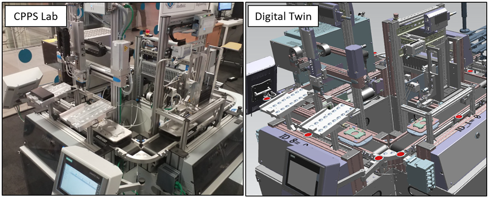
A DES model representing the ‘as-is’ simulation DT of the cell was created using Siemens Tecnomatix PlantSim software. 43 A DES model was used as it has the ability to use measured data in order to accurately model the future behaviour and states of the production process. The model captures the physical and digital behaviour of the cell. The model uses a functional model to represent the individual stations and conveyor system overlaid with a CAD model as viewed in Figure 5. Combined the system gives a realistic visualisation of the real-world system (as shown in Figure 6). The DES model can display RFID Information (Pallet ID), number and position of parts in the system at a given time based on touch sensors and RFID tag detection when in station, cycle times of a production process duration at any given station and goods-in/goods-out. PlantSim reads the real-time data from the eight PLCs in the physical cell via OPC-UA. Each PLC hosts an OPC-UA server with one for each station. It is through this OPC-UA server that the real-time vision system data is hosted.
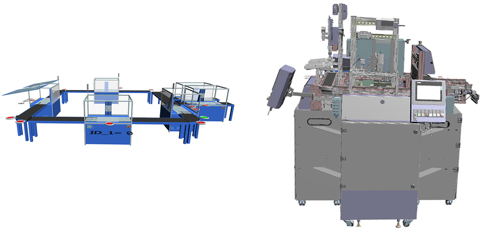
Hidden functional objects (left) and CAD model (right).
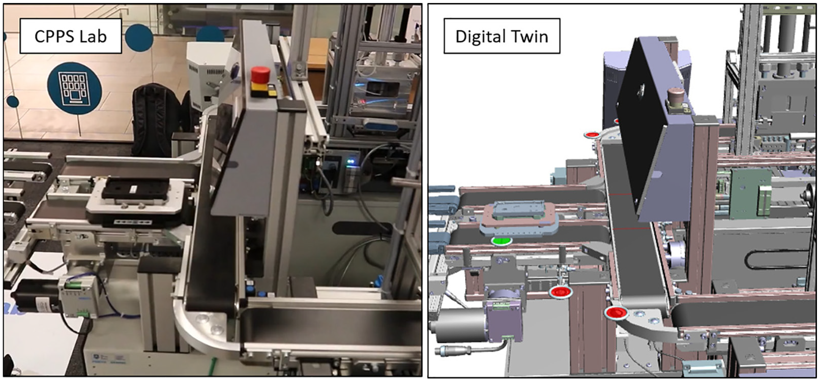
The CPPS lab (left) compared to the DT (right). The green and red markers indicate active and inactive sensors. The green marker in the DT shows that the pallet RFID tag is being read and thus the position of the pallet is known whilst it is at the sensor position. There is a slight difference between pallet position in the DT and the actual position which highlights the need for a more accurate position detection system.
The DES model provides important information to the user but it is the overlay of the high-fidelity CAD model that enables a useful visual representation of the system. This is a key component to DTs where the user is able to better visualise the status of real-world system without being physically on-site. Ensuring an accurate visual representation of the status of the system is one of the objectives of a DT. In a large factory setting one of the advantages of this type of DT would be the rapid diagnosis of the location of a fault. If a pallet became stuck or there was a sensor fault then it is easy for maintenance teams to visualise where the physical location of the problem is and react quickly. This type of technology is rapidly expanding into Augmented Reality maintenance systems aided by DT technologies.
Implementation
Vision tracking system
The objective of the vision tracking system was to create a low cost solution to identify, accurately track and transmit the position of the pallets to the CPPS DT in real-time. The inputs to the vision tracking system are the four video feeds of the pallets moving along the conveyors and the pallet RFID information read at each station. The output was defined to be an OPC-UA data structure with updated pallet number, position and order on each conveyor. The system was designed to be stand alone which then can be used by the DT to retrieve the data as desired. It has no function into the control or operation of the lab, therefore it can be turned on or off without disrupting the production process.
Hardware
The vision tracking system consists of four D435 Intel®RealSense™ depth cameras connected to a Dell Optiplex 5050 CPU (Intel i5-7500 3.4 GHz, 8 GB 2400 MHZ DDR4, Windows 10 Pro OS) via USB3 cables. The D435 cameras are configured for depth and colour streaming which provide intrinsic and extrinsic calibration capabilities. 44 The D435 cameras have excellent low light sensitivity due to the global shutter sensor and a wide field of view which makes them suitable for a range of industrial environments. The mounted positions can be see in Figure 7 and the corresponding four video feeds can be seen in Figure 8.
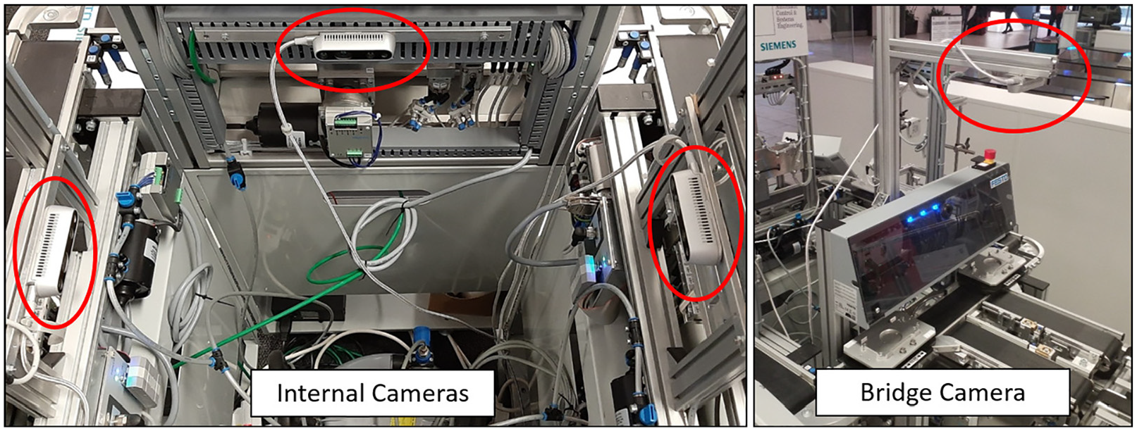
Photograph showing the camera mounting position. The internal cameras face towards the opposite conveyor (left image). The bridge camera views the pallets from above (right image).
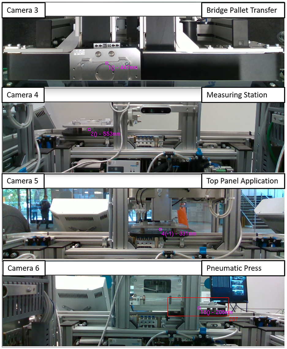
Camera views of the four D435 cameras.
The cameras are co-labelled with the station they are viewing, for example camera 4 is viewing station 4. The CPU is housed within the CPPS infrastructure and is connected to the PROFINET via RJ45 cable. Each camera is mounted such that it is positioned to view the whole of the individual conveyor and multiple pallets that are transferred along the conveyor.
Software
All custom software was developed using Visual Studio 2017, written in C# on the .net core 2.2 framework. Figure 9 shows the relationship between the hardware and software.
The key components of the software are:
libRealSense 2 45 – for interfacing with the RealSense cameras, it is a C# wrapper around a C++DLL that handles configuring the cameras and receiving new frame data.
OpenCV 4/OpenCVSharp 46 – for manipulating and processing the video frames, and for the Deep Neural Network interfaces (DNN). Received frames are converted to OpenCV matrices to allow further processing.
Darknet/YOLO v3 tiny 47 – the used DNN. The model was crosstrained to allow it to identify the pallets. The OpenCV matrices are then passed to an OpenCV DNN. This is running the Darknet Yolo v3 Tiny model crosstrained on video footage of the conveyors in order to detect the pallets.
DLib/DLibDotNet 48 – for outputting the video frames to screen during debugging.
Track Manager- bespoke software – once object detections have been performed they are passed to the track manager. This calculates the cost of assigning each detected pallet to each existing track, and then assigns them in the most cost effective manner.
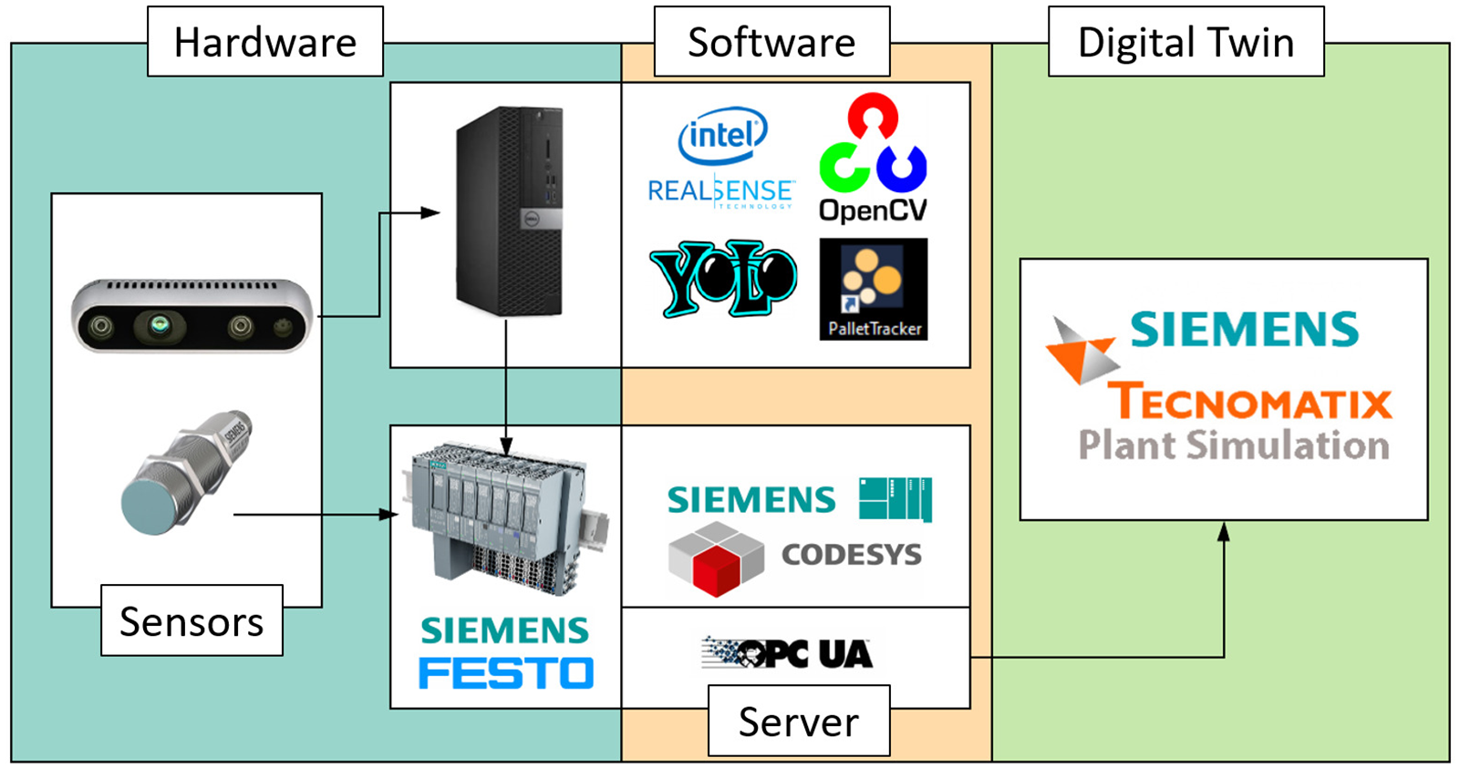
Hardware and software configurations.
Pallet detection system
An overview of pallet detection process is shown in Appendix 1. The vision tracking system can be summarised into object detection, assignment and tracking, ID assignments, conveyor arrival and departure and communication. The methodology is explained in the following section.
Input and object detection
The process initialises when a video feed is received from the D435 cameras. The Intel RealSense video frame is converted to an OpenCV matrix. The pallet is detected as an object using the Yolo detector deep neural network which has been cross trained using previous video footage of the conveyors. Once detected, a bounding box is applied to contain the object (the pallet). The software looks in the surrounding area for the object features in the following frames. The detection is called every four frames – in between the detection frames, a Kalman Filter is used to estimate the position. The estimated position is updated after each detection frame. This optimises the CPU to reduce processor usage as a Kalman Filter is more efficient on the CPU memory than the Yolo object detection algorithm. A pallet located in the station and behind the struts can be seen in Figure 10, the red bounding box is clearly seen with the pallet ID number, order on conveyor (for when there are multiple pallets on the conveyor) and distance along the conveyor.

A pallet in station with a bounding box indicating detection alongside tracking information for a single conveyor.
Assignment and tracking
Difficulties arose when the objects passed behind the struts of the modules, where all tracking algorithms failed to track objects. In order to overcome this, the Kalman Filter was used to estimate the pallets next positions based on the previous estimation and detected position of the pallet. This enables the system to track the object as it passes behind the struts.
A cost array is generated and then calculated to assign predictions to tracks. The Hungarian algorithm49,50 (also known as Kuhn-Munkres algorithm) is then applied to assign predictions to tracks by minimising the cost. The Hungarian algorithm is used for two purposes, one, to map each observed detection to a track, and two, for multiple object tracking.
Object Detection to Track Mapping The algorithm uses data from two adjacent frames to link each observation to a track. The Euclidean distance between an object in two frames (k and k + 1) is the key metric in the assignment matrices Dk, k + 1,
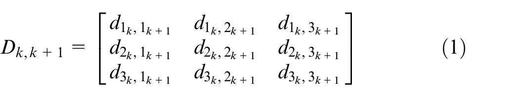
where,

The algorithm finds the mapping between the two objects by minimising the solution of the assignment matrices as follows:
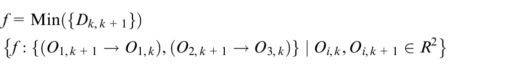
In this implementation of the Hungarian algorithm, the cost function is based on the Euclidean distance in the x axis between detected object position in the Yolo network and the updated state estimate from the Kalman Filter. Previously assigned tracks are updated and new tracks are created for any unassigned detections. Tracks that have expired or not assigned for 15 frames are deleted.
Multiple Object Tracking More than one pallet can be on a conveyor at any time. Therefore the vision tracking system must be capable of multiple object tracking. To do this, the Hungarian algorithm associates an object from one frame to another based on a score. A common approach is to use the IOU (Intersection Over Union) which means that if the bounding box in next frame overlaps the bounding box in the current frame then it is likely the same object. The algorithm can tell if an object is new, if it has moved, or if it is stationary, as shown in Figure 11.
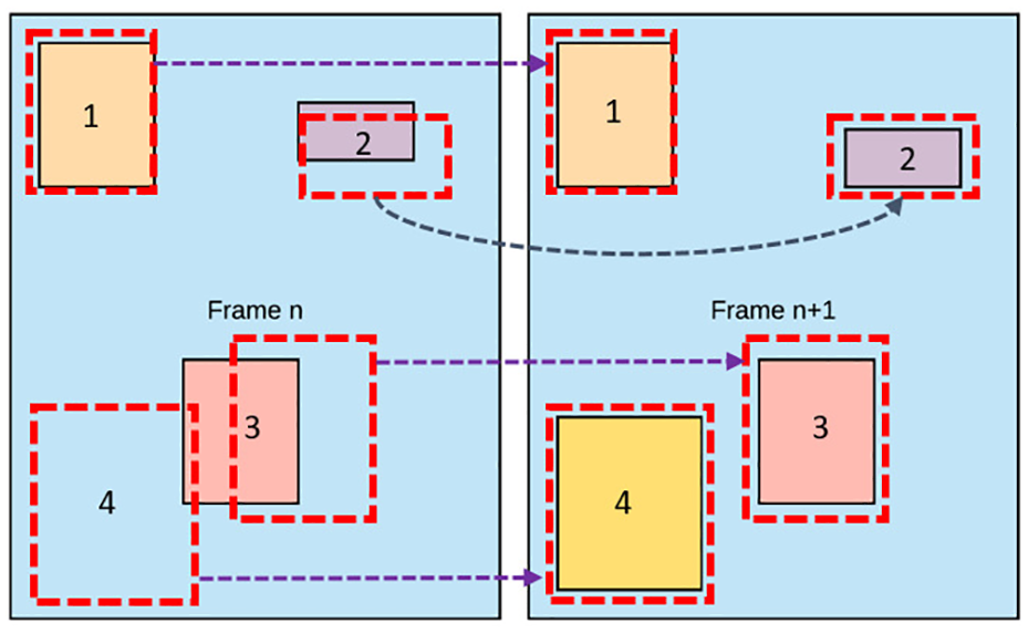
Multiple object tracking showing (1) stationary object, (2) and (3) moving objects and (4) new object detected. The images shows the relationship between the bounding boxes and the detected objects in two successive frames.
In the Yolo detector, two lists are generated, a tracking list and a detection list. A cost function gives a weight to each score and stores these in a matrix. The maximum and minimum weights are 1 and 0, respectively. A score of 1 would represent an exact match of a bounding box in two frames. The matrix describes the mapping between the detections and the tracks. The Hungarian algorithm uses bipartite graph theory to calculate each detection. The individual detections and now mapped to the individual tracks. Each cycle generates matched detections, unmatched detections and unmatched tracks. Multiple pallet tracking can be seen in Figure 12.
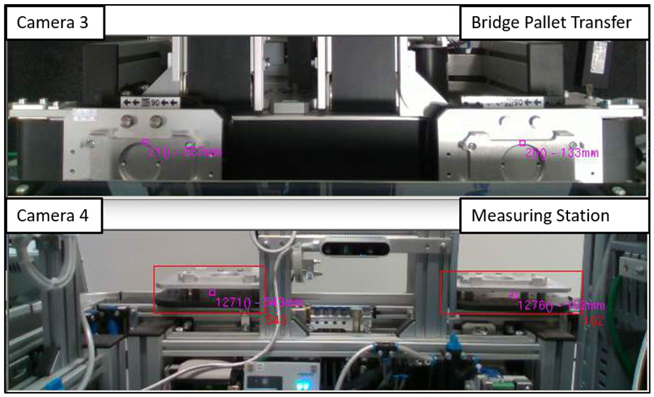
Multiple object tracking – two stations each showing two detected pallets.
ID assignment, conveyor arrival and departure
As each pallet is fitted with an RFID chip, when a pallet enters a station the RFID sensor reads the pallet information and sends the data through the PROFINET to the OPC-UA server. The software assigns the pallet ID to the detected object as can be seen in Figure 10. As the pallet is transferred along the production line the vision system continually tracks the pallet and calculates the pallet position. When the pallet is about to leave a conveyor, the next conveyor is waiting to detect a new object. The new object is automatically assigned the pallet ID from the pallet that has just left the previous conveyor. This enables continuous tracking and pallet identification around the whole conveyor circuit.
The system has the capability to detect four pallets on each conveyor, therefore each conveyor is assigned four sets of tags. The tag sets are presented in terms of ranked position order, that is, 1st, 2nd, 3rd or 4th and contain pallet ID and positional information (mm) along the conveyor. However, due to the time taken in station to read the pallet ID, only three pallets can be on any conveyor at a given time. The ability to conduct multiple object tracking is important for scalability to real industrial processes where the conveyor tracks can be anywhere from 0.5 to 20 m and beyond.
System output
The output from the pallet detection system is read by the DT via OPC-UA. The DT can read the data in real time and update the visual position of the pallet on the functional model. With the CAD overlay this provides an accurate visual representation of the physical system as shown in Figure 13. The pallet ID and position is continuously updated on the OPC-UA server as opposed the previous method where the DT was only provided up to date information at RFID sensor positions. Two pallets can be seen in Figure 13 where the positions have been updated on the DT and the result is an accurate representation of the real world system.
Integration of the vision tracking system into the DT shows the accurate position of the pallets when outside the touch and RFID sensors. The sensors when not active are displayed in red which demonstrates the pallet position data is being read in real-time via OPC-UA from the vision tracking system.
Research platform
The real-time DT (as presented in Figure 13) is now a baseline platform for Industry 4.0 research. The capabilities demonstrated include real-time data monitoring, multiple object tracking and real-time DT visualisations. These foundation capabilities are enablers which allow further research in DT and CPPS technologies from multi-disciplinary areas from engineering through to operational business research. The use of industrial PLC devices, OPC-UA communication and commercial-off-the-shelf hardware and software ensure that the DT can scale directly into an industrial setting and the industrial research developed on the platform can translate to a production process.
Conclusions
This paper has demonstrated that a Cyber Physical Production System can be generated for an existing industrial production plant. Using existing PLC information, a vision based multiple object tracking system has been implemented to provide accurate real-time product identification and position throughout the plant. The real-time information provides inputs to a visual discrete event model via an OPC-UA server which results in an accurate real-time DT and visual representation of the industrial process. This low cost, reconfigurable and scalable technology is an excellent testbed for future Industry 4.0 research.
The focus of this research has been to demonstrate a proof of concept system for Industry 4.0 research. The next step is to integrate this information with the MES in order to optimise product launch scheduling and prove the utility of real-time plant information to optimise resource planning. In the immediate future, the research effort will extend the current level of simulation and focus on a multi-level DT of the FESTO system with the aim of DT at each level in the automation pyramid (see Figure 1).
Footnotes
Appendix
Acknowledgements
This project was a collaboration between the Department of Automatic Control and Systems Engineering and the Manufacturing Intelligence Department at the Advanced Manufacturing Research Centre, University of Sheffield. We would like to thank Dr Jamie Smith for his support with Tecnomatix. We would also like to thank Mike Smart, Joe Bell and Adam Jarmin from Inspec Solutions for their technical support throughout this project. The authors also acknowledge the support of the Royal Academy of Engineering under the Research Chairs and Senior Research Fellowships scheme (RCSRF1718/5/41). Professor Ashutosh Tiwari is Airbus/RAEng Research Chair in Digitisation for Manufacturing at the University of Sheffield.
Declaration of conflicting interests
The author(s) declared no potential conflicts of interest with respect to the research, authorship, and/or publication of this article.
Funding
The author(s) disclosed receipt of the following financial support for the research, authorship, and/or publication of this article: This work was supported by the Higher Education Innovation Funding at the University of Sheffield Knowledge Exchange. Grant No. X/013194.