
Abstract
Cutting temperatures and heat partition into the cutting tool are critical factors that significantly affect tool life and part accuracy during metal removal operations, especially in dry machining. Among many thermal modelling studies, uniform heat partition ratio, and/or uniform heat intensity along the tool-chip interface are frequently assumed. This assumption is not valid in actual machining and can lead to erroneous estimated results in the presence of sticking and sliding friction zones. Therefore, it is necessary to accurately predict the cutting tool temperature and heat partition during machining. This paper presents an analytical thermal modelling approach which considers the combined effect of the primary and the secondary heat sources and determines the temperature rise and non-uniform heat partition ratio along the tool-chip interface. Cutting tests were conducted on AISI/SAE 4140 high-strength alloy steel using carbide cutting tools over a wide range of cutting speeds. Cutting temperatures were measured experimentally using an infrared thermal imaging camera. Experimentally established sticking and sliding friction regions were used to evaluate non-uniform frictional heat intensity along the tool-chip interface. The temperature matching condition along the tool-chip interface leads to the solution of distributed non-uniform heat partition ratio by solving a set of linear equations through programming in MATLAB®. Experimental results show to be consistent well with those obtained from the thermal model, yielding a relative difference of predicted average tool-chip interface temperature from −0.8% to 6.3%. It is found that average heat partition into the cutting tool (RT) varies from 35% down to 15% for the entire range of cutting speeds. These results suggest that, to address the thermal problem in metal cutting, the research and development of tooling should also focus on reducing friction on the tool rake face in addition to the contribution of the combined effect of primary and secondary heat sources on temperature rise at the tool-chip interface.
Keywords
Introduction
Machining is a coupled thermo-mechanical process. During the metal cutting process, heat generation occurs as a result of plastic deformation and friction along the tool-chip and the tool-workpiece interfaces. A schematic of the heat sources in orthogonal metal cutting is shown in Figure 1. It can be safely assumed that almost all of the cutting energy is converted to heat within the cutting domain. 1 During the orthogonal cutting process, the temperature rises due to three deformation zones namely primary (shear plane heat source), secondary (frictional heat source), and tertiary (rubbing heat source) deformation zones. The temperature rise in the cutting tool is mainly due to the secondary deformation zone, but the primary deformation zone also contributes to the temperature rise of the cutting tool and indirectly affects the temperature distribution on the cutting tool. The contribution of the tertiary deformation zone does not make a significant difference in temperature rise and this heat source would be small. Therefore, the tertiary deformation zone at tool-workpiece contact can be neglected.2,3 The fraction of heat enters into the cutting tool, which is stationary relative to the heat source, is based on the determination of heat partition into the cutting tool (RT), which defines the percentage of heat going into the tool. The fraction (1−RT) defines the percentage of heat entering into the moving chip (Figure 1).
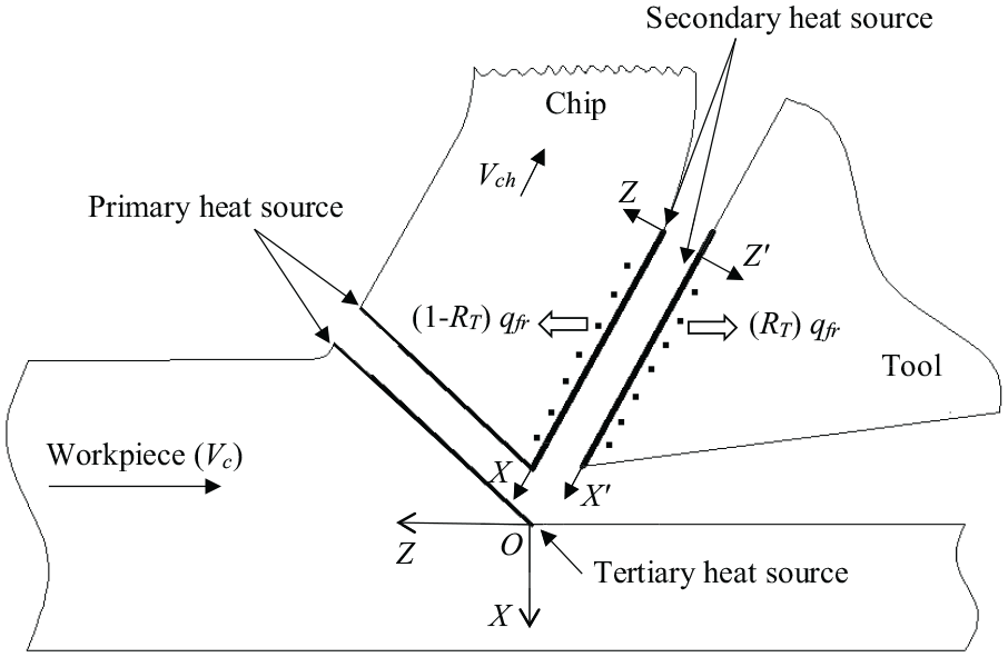
Schematic of heat sources in orthogonal cutting used for thermal modeling.
Thermal modelling of cutting tool temperatures and heat partition ratio has attracted many researchers due to the complexity of the machining process. Various analytical thermal models have been proposed to predict cutting tool temperature distributions and heat partition ratios in the deformation zones. Blok’s 4 principle has been broadly used for the analytical investigation of temperatures that generate during the metal cutting operation where it models (i) stationary body and (ii) moving body with relative velocity. The moving heat source method was proposed by Jaeger 5 and presented in the study of cutting temperature by Rosenthal, 6 Hahn 7 model, Chao and Trigger8,9 model, Leone 10 model, Loewen and Shaw 11 model, Weiner 12 model, Boothroyd 13 model, Dutt and Brewer 14 model, Wright et al. 15 model, Dawson and Malkin 16 model, Komanduri and Hou17–19 model, and finally Huang and Liang 20 model have developed one after another. Among the above reported analytical thermal models, Komanduri and Hou17–19 model and Huang and Liang 20 model are widely adopted by many researchers.
Most researchers21–36 in their analysis have preferred to assume the values of heat partition for machining applications, but with large differences with the experimental values. Huang and Liang 20 used a non-uniform heat intensity in their model and assumed the lengths of sticking and sliding zones to diverge from other studies to determine the heat partition. Liu and Chou37,38 used a uniform heat flux along the tool-chip interface to determine heat partition, negating the effects of sticking and sliding at the tool rake face. Yvonnet et al. 39 used the inverse technique to determine the convection heat transfer coefficient and the average heat flux flowing closer to the tool-tip where a piecewise constant function was used for the calculation of approximate heat flux distribution. Karpat and Özel40,41 held on to the assumption of non-uniform heat flux to predict the heat partition and calculated empirically the actual lengths of sticking and sliding friction zones for uncoated carbide cutting tool.
Egana et al. 42 used a specially designed open tribometer to characterize the macroscopic friction coefficient, heat partition coefficient, and adhesion in the contact versus sliding velocity and contact pressure. Fahad et al. 2 used an analytical model to evaluate the chip temperature rise due to the primary deformation zone heat source and estimated its contribution to the cutting tool heat flux to be less than 9.5%. Jiang et al. 43 performed an analytical modelling and experimental investigation for the interrupted cutting of steel by the method of inverse heat conduction. Rech et al. 44 developed a method for identification of heat partition and friction models via a special tribometer which was able to simulate wide ranges of contact pressures and sliding velocities, as compared to those occurring along the tool-work material interface during metal cutting operations. Avevor et al. 45 employed a combined analytical and numerical model where they considered the combined effect of material flow in the primary deformation zone and the thermomechanical load along the chip-tool interface.
Sun et al. 46 used an analytical model where they considered a continuously varying actual chip thickness in end-milling of titanium alloy Ti6Al4V with a carbide cutting tool. The authors ignored the frictional heat between the workpiece and the cutting tool and measured cutting temperatures with the help of a semiartificial thermocouple. Chen et al. 47 utilized a non-uniform moving heat source model to analyze the thermal problem in the machining of titanium alloy. Shan et al. 48 proposed a modified analytical model for determining cutting tool temperature and heat partition along the tool-chip interface in orthogonal machining of titanium alloy Ti6Al4V. Shan et al. 48 used a non-uniform heat intensity along the tool-chip interface in their thermal model but assumed lengths of the sticking friction zone (lst) and the sliding friction zone (lsl). Recently, Curtis et al. 49 reported that both contact patch and thermal energy partition are critical parameters in the assessment of residual stress formation when grinding Inconel 718 with conventional and super abrasives.
It can be established from the review of the state-of-the-art literature that a more profound investigation of heat partition between the tool-chip interfaces is demanded to produce convincing analytical models of the machining processes. Therefore, this paper presents an analytical thermal modelling approach that considers the combined effect of the primary and the secondary heat sources and determines the temperature rise and heat partition along the tool-chip interface using MATLAB® software. The thermal model presented in this study contemplates a non-uniform heat intensity in conjunction with the experimentally determined sticking and sliding lengths along the tool-chip interface. Finally, the thermal model validation is performed through orthogonal machining of AISI/SAE 4140 alloy steel using uncoated carbide cutting tools over a wide range of cutting speeds.
Thermal modelling of the orthogonal cutting process
Theoretical outline of the temperature modelling
In this study, the distribution of temperature along the chip and tool interface at a half-way distance across the width-of-cut is of crucial interest due to the peak level temperatures taken at this location. Temperatures at different other locations can also be estimated by the below-described approach. The method of heat source presented by Jaeger 5 is applied here as the basis for thermal modelling.
Assumptions
The following assumptions are made in the development of the thermal model:
Heat generation and temperature distribution are in a steady-state.
All of the deformation energy within the deformation zones is converted into heat.
The dimensions of the tool are large enough compared to the chip cross-section so that the tool size can be considered as infinite.
Primary and secondary heat sources are plane heat sources.
There is no redistribution of shear energy entering into the chip when the chip is in contact with the tool.
The co-ordinate system
Analytical models use a Cartesian co-ordinate system to define a particular point along the tool rake face. Figure 2 represents this co-ordinates system for (a) a simple cutting insert and (b) a conventional orthogonal cutting model, with X co-ordinate along tool-chip interface, Y co-ordinate along the deformed chip thickness, and Z co-ordinate perpendicular to the plane in the direction of depth-of-cut.
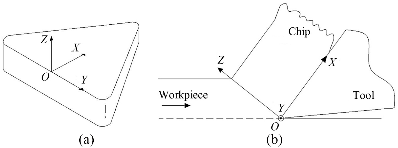
The co-ordinate system for: (a) the cutting tool insert and (b) the orthogonal cutting model.
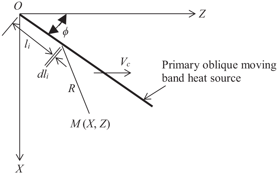
The method of moving heat source was first applied by Jaeger 5 with moving velocity in accordance with the heat source direction and was stretched further to cater the oblique moving band heat source. The primary heat source is modelled commonly as an oblique moving band heat source. Figure 3 represents a single oblique moving heat source at an angle (ϕ) with velocity (V) in an infinite medium, where the rise of temperature (θ) at any arbitrary point M (X, Z) caused by a differential segment dli can be calculated from equation (1)17,50 as:

where, q is the heat intensity of a moving heat source, λi is the thermal conductivity of the medium i, αi is thermal diffusivity of the medium i, L is the length of the moving band heat source or shear plane, X is the projection of the distance R in the direction of motion, and Ko is the zero-order Bessel function of the second kind.
Representation of an infinite medium oblique moving band heat source.
Modelling of temperature rise in the chip
Rise in the chip temperature due to primary deformation zone
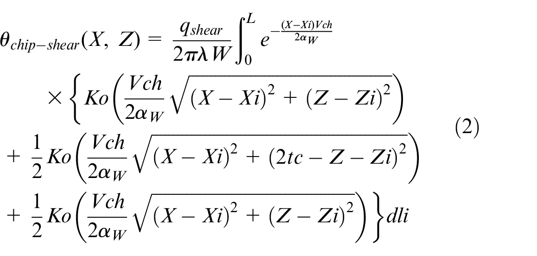
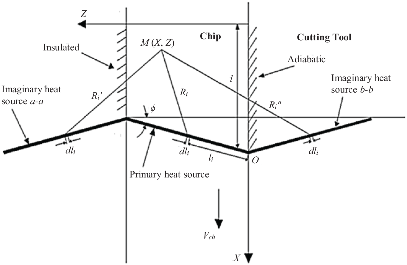
The rise in chip temperature is attributed to both primary and secondary heat sources, where the former being a moving heat source due to the continuous flow of the chip. The back side of the chip is supposed to be adiabatic, while the primary and imaginary heat sources are symmetric concerning the back side of the chip, as shown in Figure 4. The rise in temperature due to the primary heat source is given by equation (2) 20 as:
where,

Primary shear zone uniform heat intensity owing to shearing effect is demonstrated as:

where, Fs = shear force, Ft = feed force,

and shear velocity (Vs) is calculated as:
Primary heat source heat transfer model relative to the chip side.
Rise in the chip temperature due to secondary deformation zone
The secondary heat source effect is encountered due to the continuous flow of chip with an imaginary heat source. The moving heat source direction is contrary to the flow direction of the chip as the heat source that is moving down with reference to point M, as shown in Figure 5. The rise in temperature owing to the secondary heat source is given by equation (8) 20 as:
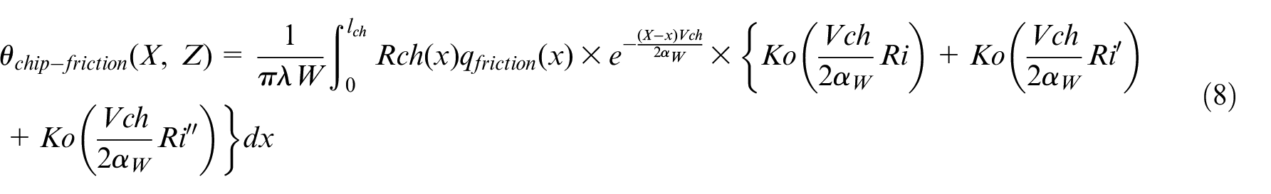
where,

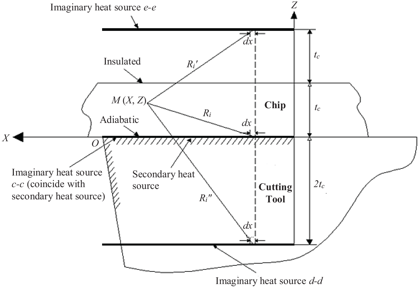
Secondary heat source heat transfer model relative to the chip side.
Modelling temperature rise on the cutting tool
The tool temperature rises due to the friction heat source which is immobile with reference to any arbitrary point on the tool, as shown in Figure 6. The rise in temperature due to friction can be expressed by equation (9) 20 as:

where,

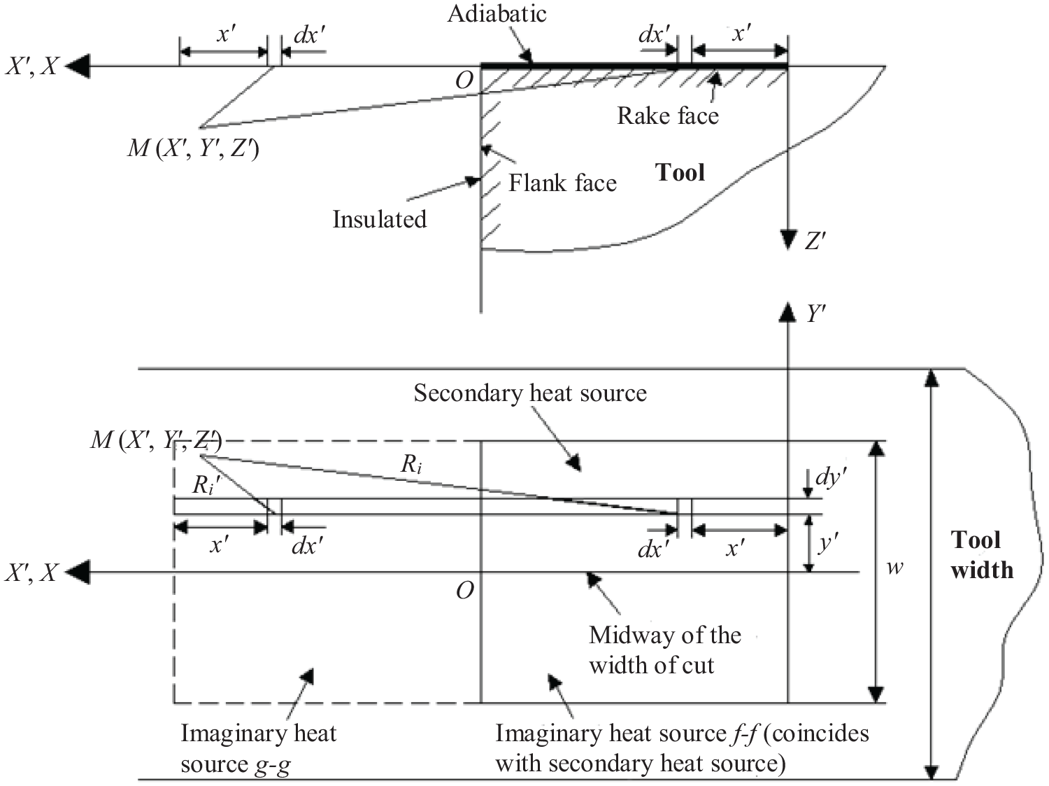
Secondary heat source heat transfer model relative to the tool side.
Non-uniform heat intensity estimation at the tool-chip interface
The contact phenomena in machining can be characterized by the sticking and sliding friction zones, which is highly contingent on the cutting tool and workpiece materials, as well as, on the cutting conditions. In the sticking friction zone, the constant shear stress (τsh) is being assumed along the entire sticking contact length, up to x = lst, where x is the distance from the edge of the cutting tool. However, in the sliding zone, this shear stress gets reduced to zero where the chip departs from the rake face of the tool. The shear stress in the sticking friction zone, (τsh), can be calculated from the equation (10) 15 as:
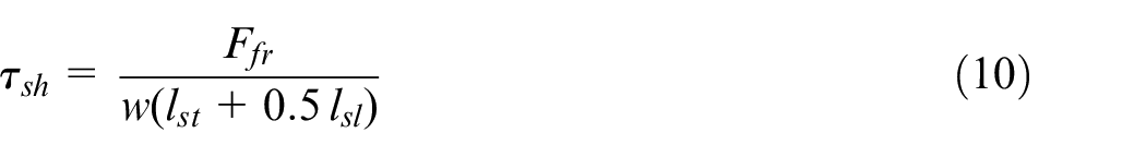
where lst is the sticking length, w is the depth of cut, lsl is the sliding length, and Ffr is the force of friction, which is found out from equation (11).

where Ff is the feed force, Fc is the cutting force, and γ is the rake angle. In this study, the heat intensity qfr (x) along the sticking zone is defined as τshVch (x ≤ lst) which decreases to zero linearly along the zone of sliding contact (lst < x ≤ lch). 51 For the estimation of non-uniform heat intensity, experimentally quantified values of sticking and sliding friction lengths along the tool-chip interface were used.
Determination of non-uniform heat partition ratio and the tool-chip interface temperature
The temperature rise on the tool-chip interface is considered the same as those in the chip and the tool. The heat partition into the cutting tool and chip is determined by discretization along the tool-chip interface. The tool-chip interface is evenly divided into n intervals where n + 1 points from xo to xn. If a total of n points are defined on the tool-chip interface, the n equations can be solved for the heat partition Rch(1),Rch(2),Rch(3)…………….. Rch(n). According to the continuity of the temperature field along the tool-chip interface, the temperature rises on the chip side (Z = 0) and on the tool side at a midway location across the depth of cut (w) (Y' = Z' = 0) should be equal, which can be expressed in equation (12) as:

Equation (12) can be rewritten based on equations (2), (8), and (9) as:

Rearranging the above equation (13) as:


The above equation (14) can be written in matrix form as:

where matrix
and matrix

Finally, the matrix

Finally, the values of the heat partition into the chip (Rch) and the cutting tool (RT) of n dissimilar intervals can be obtained by solving equation (15), and then the tool-chip interface temperature can be computed by substituting the heat partition ratio values in equation (12).
Experimental tests
Experimental set-up
Dean Smith and Grace (DSG) horizontal lathe machine was used to perform the cutting tests. A Kistler 9263 three-axis piezoelectric dynamometer was used to measure cutting forces. Dynamometer mounted on the turret disk of the lathe through a custom-designed turret adapter for the tool-holder creating a very rigid tooling fixture. The amplified signal is acquired and sampled by using a data acquisition card and software (National instrument lab View 7.0) on a personal computer at a sampling frequency of 2000 Hz per channel. The complete experimental setup is shown in Figure 7. Tungsten based uncoated cemented carbide tools with geometric designation TCMW 16T304 were utilized. The Sandvik STGCR/L 2020K-16 tool holder was used. The cutting tests were performed at five different cutting speeds of 100, 197, 314, 395, and 565 m/min. These cutting speeds were set by the available revolutions per minute (RPM) on the lathe machine. A new cutting edge was used for every cutting speed. The federate (f) and depth of cut (w) were kept constant at 0.1 mm/rev and 2.5 mm respectively. The general representation of the complete research methodology applied in this study is illustrated in Figure 8.
Set-up for cutting experiments.
The research methodology used for the estimation of heat partition into the cutting tool (RT).
Workpiece material
A pre-bored workpiece of AISI/SAE 4140 high-strength alloy steel (EN-19 in British Standard) with an external diameter of 200 mm, length 200 mm and tube thickness 2.5 mm was used in the machining tests. Its hardness was 23.9 HRC and was chosen due to its diverse applications in the manufacture of automobile components such as crankshafts, piston rods, steering components, axles, gears, and high-resistance screws. Its chemical composition was examined by Energy-Dispersive X-ray Analysis (EDXA) and is presented in Table 1.
Chemical composition of AISI/SAE 4140 by weight percentage.
Experimental temperature measurements
Numerous techniques of experimentation have been established and utilized to study the cutting temperatures.13,51–58 From the literature review, it comes into understanding that Infrared (IR) thermal imaging is a profound technique to obtain the distribution of temperature in metal cutting operations. In the presented work, temperatures measurements were taken via an IR thermal imager FLIR ThermaCAMTM SC3000 which is a long wave and self-cooling analysis system. This allows extensive analysis of highly dynamic objects and processes which are found in metal machining research applications. FLIR thermal CAM SC3000 system has a cooldown time of <6 min and a temperature range of −20 to +2000°C with an accuracy of ±2% or ±2°C for measurement ranges above 150°C. This IR thermal imaging camera can capture and store thermal images and data at high rates.
The infrared thermal imager was mounted near the turret of the machine and placed in view of the rake face of the tool during the cutting process, as shown in Figure 7. It was positioned at a space of 30 cm from the tool-workpiece interface to elude any harm by the ripping chips. The emissivity of the material is of primary concern when using a thermal imaging camera as the actual temperature of an object strongly dependent on it. Accurate calibration of the thermo-graphic system was ensured to find the values of emissivity for the uncoated cemented carbide tool material. Samples were heated in an oven to temperatures ranging from 100°C up to 900°C. Inserts temperature were read via thermal imaging camera and emissivity was adjusted until it matched with the thermocouple reading. Fifteen values of emissivity were obtained at each temperature level and their mean was used for the setting of the camera. According to M’Saoubi et al., 59 the error calculation is less than 10% for the emissivity of 0.2, which is lower than 7.5% and 5% for emissivity values greater than 0.3 and 0.5 respectively. The emissivity results obtained in the present study for the uncoated cemented carbide tool produced typical emissivity variation with temperature, as shown in Figure 9, whose mean was then used for the setting of the camera. The average emissivity of uncoated inserts was determined to be 0.48 at 700°C. A small variation of tool emissivity in the temperature range of 450°C–900°C given by 0.48 ± 0.01020 for the uncoated tool was observed.
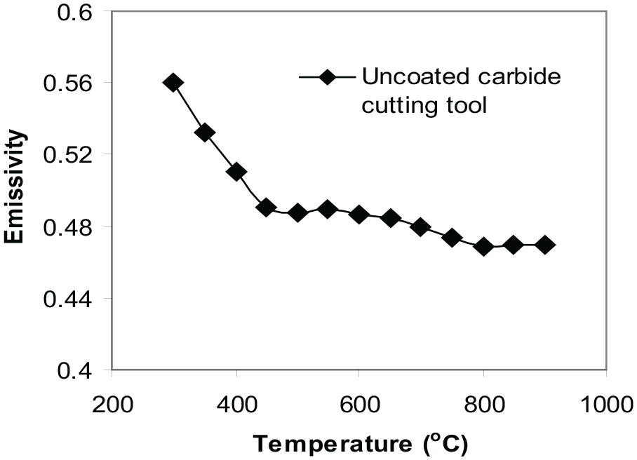
Variation of emissivity with temperature for uncoated carbide cutting tool.
Thermal properties of the cutting tool and workpiece materials
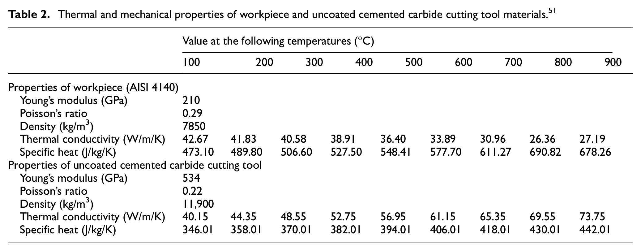
Variation of the mechanical and thermal properties of the workpiece and cutting tool materials with a temperature considerably affect the machining processes and its modelling. These variations are prone to significantly affect the chip-tool interface temperatures, and eventually the heat partition. A realistic metal cutting model must, therefore, take into account this temperature dependency of thermal and mechanical properties. The thermal and mechanical properties of the materials used in the analytical thermal model are given in Table 2.
Thermal and mechanical properties of workpiece and uncoated cemented carbide cutting tool materials. 51
Results and discussion
Cutting forces
The cutting and feed forces versus cutting speed obtained from the tests performed are shown in Figure 10. It can be observed that the cutting force decreases with the increasing cutting speed from low (100 m/min) to medium (395 m/min), and then marginally increases at speeds up to 565 m/min. The feed force also decreases stealthily with the increasing cutting speed. These results are in good agreement with the accepted effect of cutting speed on cutting forces.
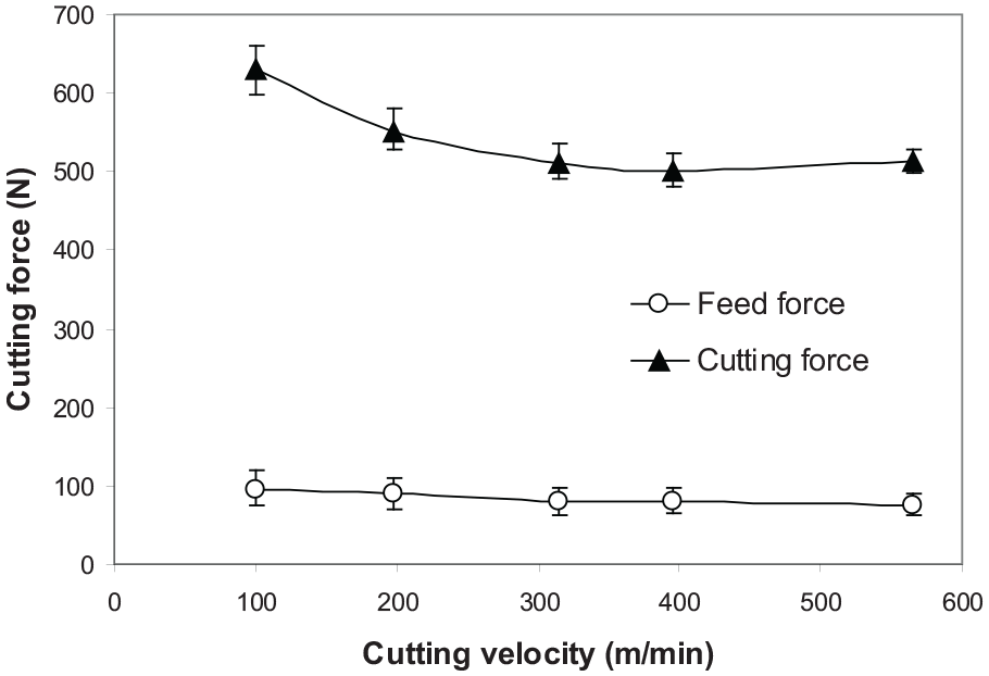
Variation of cutting and feed force with the cutting speed.
Chip compression ratio and shear angle
The shear angle (ϕ) is specified as a function of chip compression ratio (λh) and the rake angle, as in equations (5) and (6). Figure 11 represents the variations in shear angle (ϕ) and the chip compression ratio (λh) with the cutting speed. It can be observed that the shear angle increases and the chip compression ratio decrease with increasing the cutting speed from 100 to 565 m/min. The chip compression ratio decreases due to a decrease in the deformed thickness of chip (tc), whereas the shear angle increases. The chip compression ratio is an important parameter which is used in estimating the amount of deformation of the chip as well as the shear angle.
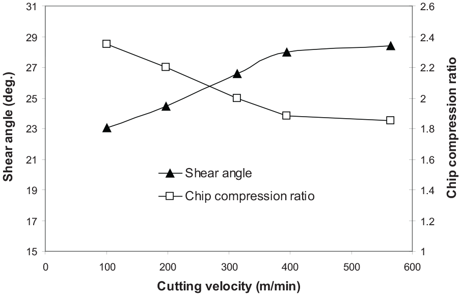
Variation in shear angle and chip compression ratio with the cutting velocity.
Tool-chip contact length
The mechanics of machining, heat partition into the cutting tool and heat generation can significantly affect the contact length of the tool and chip. A Scanning Electron Microscope (SEM) was used to obtain the tool-chip contact length (lch) of the worn carbide cutting inserts at different cutting speeds. Sample pictures of the worn insert taken from SEM at cutting speeds of 100 m/min and 565 m/min are shown in Figure 12. The SEM examination of cutting tool inserts used in this study evidently shows superficial marks left on the worn tool rake face (Figure 12). This was due to the continuous flow of the chip over the rake face of the cutting tool during machining process starting from the cutting edge. Different chip marks were observed on the worn tool rake faces due to the presence of sticking and sliding frictions in the tool-chip contact regions at different cutting speeds. The size of sticking and sliding regions were specified with the length of the regions. In orthogonal cutting, the power supplied by the cutting force is consumed in two ways (i) by breaking down the workpiece metal bonds in the sticking region (deformation) and (ii) by overcoming friction in the sliding region (friction) on the tool rake face. Both sticking and sliding processes of chip flow generate heat. Moreover, SEM images of the worn inserts indicate that the tool-chip contact length (lch) changes according to the contact phenomena in the tool-chip interface zone (Figure 12), which is mainly affected by the cutting speed (Vc).
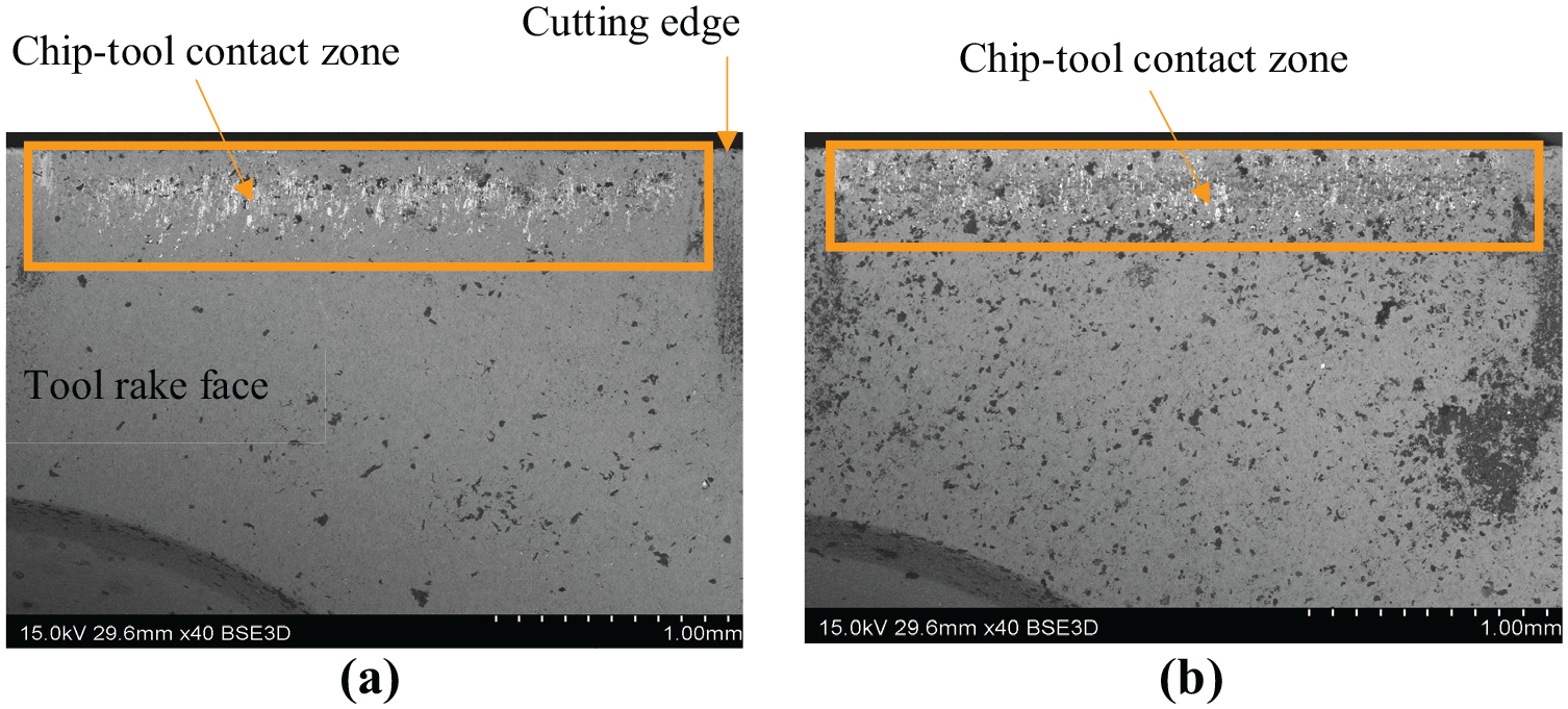
SEM images of the chip-tool contact length of uncoated carbide cutting tool at cutting speeds of: (a) 100 m/min and (b) 565 m/min.
The graph in Figure 13 shows the experimentally measured average tool-chip contact length at different cutting speeds for the worn inserts. It is evident that the contact length is considerably affected by the cutting speed. For carbide cutting tools, there is a decrease in the contact length when the cutting speed is increased from 100 to 395 m/min. Figure 13 shows a notable change in trend after cutting speed of 395 m/min. Beyond 395 m/min, the tool-chip contact length increases with the cutting speed. The cutting speed of 395 m/min represents the transition zone (between conventional and high-speed machining) where the trend for a reduction in the contact length with cutting speed changes and starts to increase. This is driven by the change in the sliding contact phenomenon. This trend is in agreement with the widely reported reduction in tool-chip contact length for a wide range of cutting speeds. 51
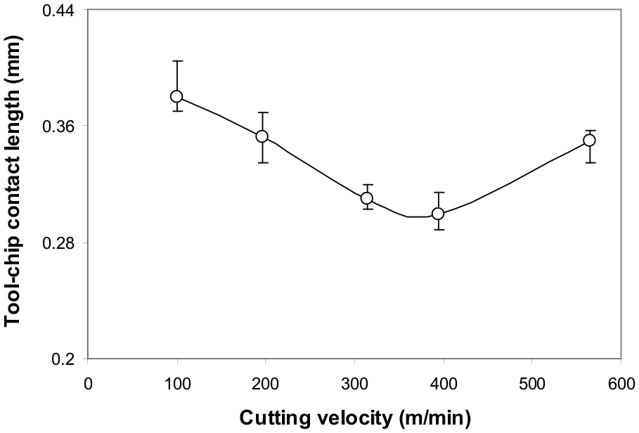
Deviation in the experimentally measured tool-chip contact length with the cutting speed.
Quantification of sticking and sliding friction zones
At any stage during the machining, a part of the tool-chip interface can be in seizure (sticking) while the rest of the contact undergoes interfacial sliding. SEM-EDXA was used to differentiate between the sticking and the sliding friction zones from an examination of the chip-tool contact region for uncoated carbide cutting tools. The worn cutting tool inserts were examined by SEM using a backscattered imaging mode and the tool-chip contact length was scanned for the proof of iron (Fe) concentration transfer from the moving chip. The estimation of this iron (Fe) concentration intensity was taken on a cross-sectional plane of the contact area in the direction of chip flow.
The map of EDXA of iron concentration on the rake surface of the cutting inserts for uncoated carbide tools for cutting speeds ranging from 100 to 565 m/min is plotted in Figure 14. The map highlights low iron (Fe) concentration at the cutting edge which is credited to affect the tool edge radius. Figure 14(a) shows that at 100 m/min the cutting tool rake face is not dominated by iron (Fe) concentration transfer from the chip, hence, providing evidence that sticking does not occur at this cutting speed. As the cutting speed is amplified to 565 m/min, Figure 14(b), the contact phenomena fluctuates and the rake face of the tool displays a substantial transfer of iron (Fe) concentration, thereby suggesting an ample amount of seizure occur at this cutting speed. Therefore, it is justifiable from Figures 14(a) that for the uncoated carbide cutting tools, no significant seizure or sticking transpired for the speed of 100 m/min. However, the cutting speed is escalated to 565 m/min, 59% sticking and 41% sliding contact phenomenon is established as shown in Figure 14(b).
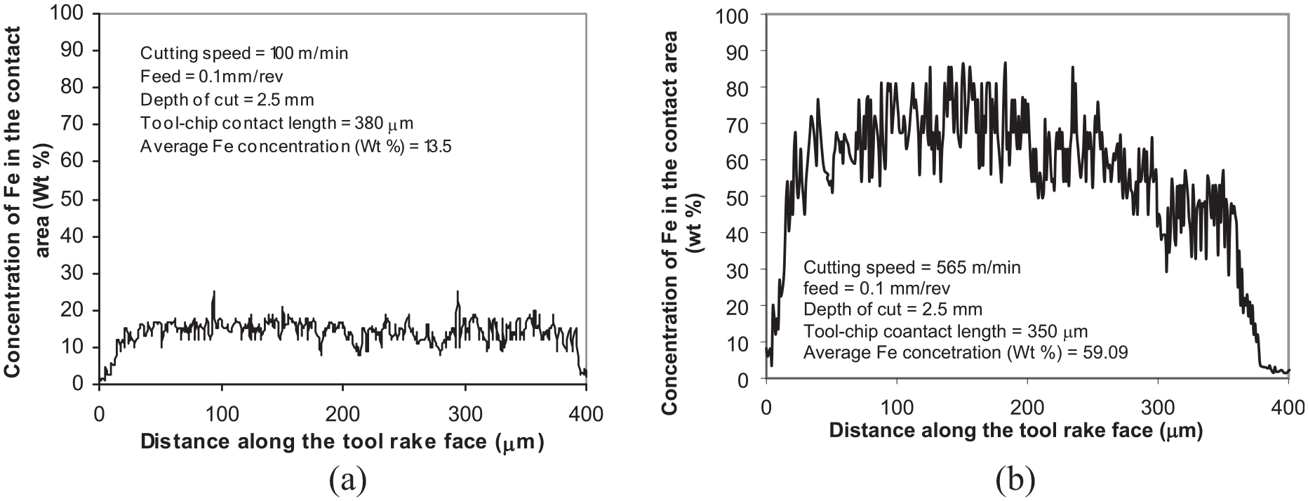
SEM-EDXA Fe density maps along the rake face of uncoated carbide cutting inserts for cutting speeds of: (a) 100 m/min and (b) 565 m/min.
Comparison of predicted and experimentally measured chip-tool interface temperatures
With the aid of ThermaCAMTM Research data acquisition software with post-processing options, the whole sequence of the cutting process has been recorded. The thermal camera offers a very high spatial resolution to record simultaneous temperatures at and near the cutting zone. Figure 15(a) shows a general view of the ThermaCAMTM Researcher post-processing software main window and Figure 15(b) shows the magnified infrared photograph of the cutting process along line LO1 at the tool-chip interface. The temperature variation obtained at the cutting speed of 100 m/min at the chip-tool interface with respect to time is shown in Figure 16. It indicates that the temperature reached the condition of steady-state during the time frame of the cutting process. The transient period appears to be of a very small fraction of a second, as shown the Figure 16.
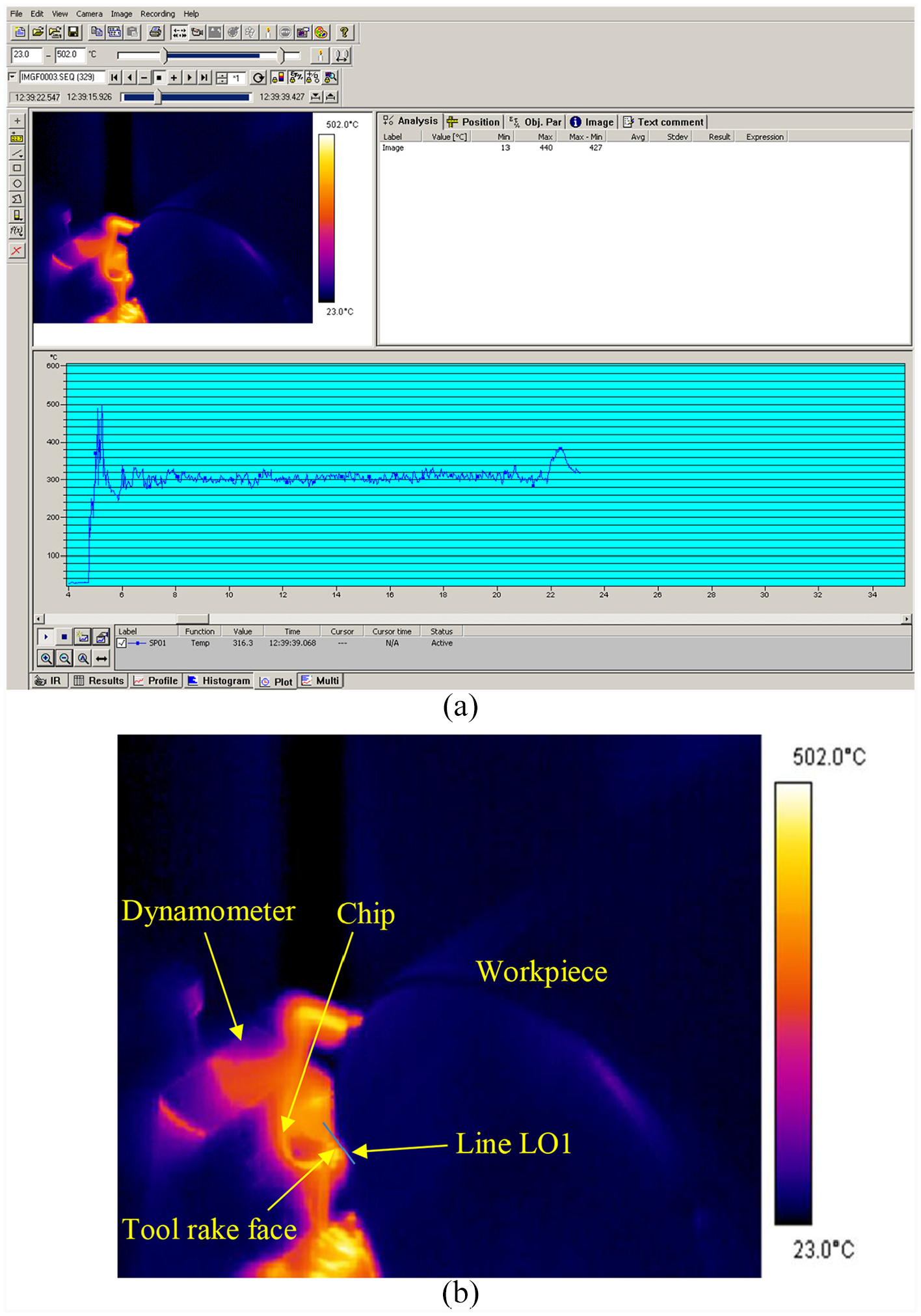
(a) A general view of the ThermaCAMTM Researcher post-processing software main window and (b) Magnified infrared photograph of the cutting process along line LO1 at the tool-chip interface.
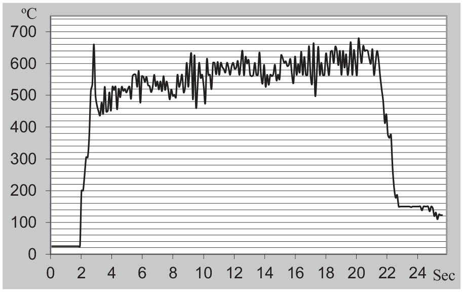
Experimentally measured tool-chip interface temperature profile along line LO1 at the cutting speed of 100 m/min.
The distribution of predicted temperatures on the tool rake face is obtained by programming in MATLAB® and results are shown in Figure 17(a)–(d). It is worth noticing that a flat temperature trend is obtained along the interface of the chip and tool within the span from 0 to 0.1 mm for all the cutting conditions. As the cutting edge distance is increased, that is, between about 0.1 mm and 0.4 mm, the temperature progressively decreases with the distance far off the cutting edge. Ultimately, a falling temperature trend is noticed for far off distances. Due to the consideration of non-uniform frictional heat source where the experimentally measured lengths of the sticking and sliding zones are used, the location of maximum temperature gets closer to the middle of the tool-chip interface.
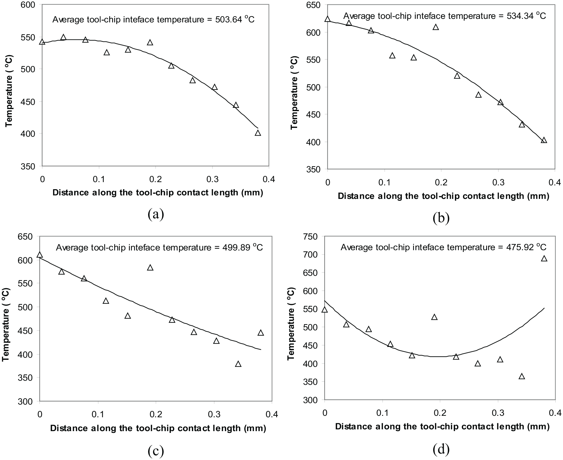
Predicted temperature distribution along the tool-chip interface for cutting speeds of: (a) 100 m/min, (b) 197 m/min, (c) 314 m/min, and (d) 565 m/min.
Under the same cutting conditions, the predicted values of the average tool-chip interface temperature as calculated from equation (12) and experimentally measured through data recorded by thermal imaging camera were used for the validation purpose of the thermal model. The predicted and experimental measured values of the average tool-chip interface temperature are presented in Figure 18. It can be clearly seen that the predicted values of average tool-chip interface temperature obtained from the thermal model agree well with the experimentally measured results. The relative differences between the predicted values of average tool-chip interface temperature from the thermal model and the experimentally measured results are 5.9%, −0.8%, 3.1%, 6.3%, and 1.6% at cutting speeds of 100, 197, 314, 395, and 565 m/min respectively. The average difference between the experimental and predicted data is small for each cutting speed which shows a fine agreement is attained between the experimental and predicted results, as shown in Figure 18.
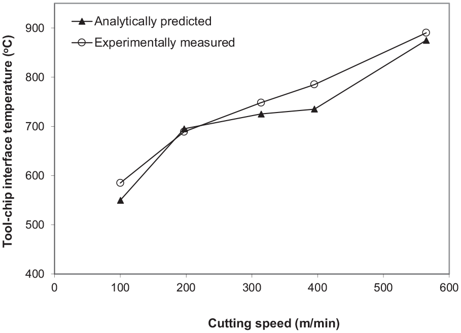
Comparison of average predicted and experimentally measured temperatures along the tool-chip interface.
From Figure 18, it can be deduced that the predicted temperature rise at the tool-chip interface has to be considered the contribution of the combined effect of primary (shear plane) and secondary (frictional) heat sources. Komanduri and Hou 19 reported that the average temperature rise at the chip-tool interface due to primary heat source alone was lower than the combined effect primary and secondary heat sources during the orthogonal machining of steel with a carbide cutting tool. Komanduri and Hou 19 found that the exactly matched temperature rise distribution at the tool-chip interface was obtained due to the combined effect of the primary and secondary heat sources. Karpat and Ozel 40 stated that the temperature rise due to primary heat source was lower than the measured temperature at the tool-chip interface in the orthogonal machining of AISI 1045 steel. Komanduri and Hou 19 and Karpat and Ozel 40 results support the cutting temperature prediction as reported in this study. Hence, the presented thermal model proves its ability to predict cutting temperatures at the tool-chip interface.
Heat partition into the cutting tool (RT)
The fraction of heat entering into the cutting tool (RT) at the tool-chip interface is calculated using equation (15) for different cutting speeds. This signifies the non-uniform heat partition into the cutting tool from the tool-chip and chip-workpiece interfaces. As shown in Figure 19(a)–(d), the heat partition into the cutting tool is evidently a function of the cutting speed which is also explicitly related to the contact face conditions in the cutting process. Overall, the average heat partition ratio into the cutting tool on the rake face is a function of cutting speed ranging from 100 to 565 m/min with a decreasing trend. Heat faster dissipated by the chip and workpiece outflows as the cutting speed increases, therefore, heat partition into the cutting tool decreases.
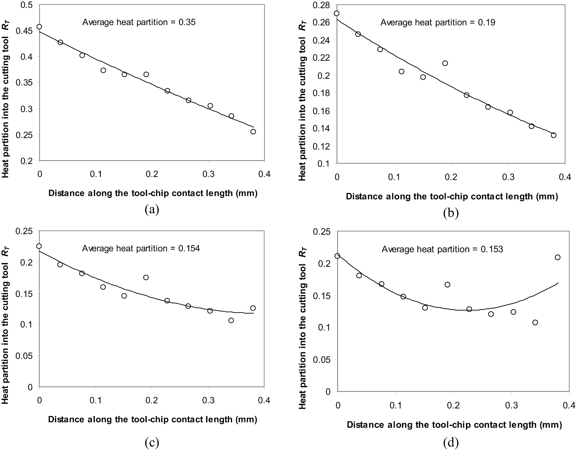
Heat partition along the tool-chip interface for cutting speeds of: (a) 100 m/min, (b) 197 m/min, (c) 314 m/min and (d) 565 m/min.
From Figure 19(a)–(d), it can be seen that some individual values of the heat partition into the cutting tool (RT) are not followed the decreasing trend along the tool-chip contact length. It is plausible that the primary (shear plane) heat source affects not only the temperature directly on the chip side, however also the temperature indirectly on the cutting tool side. In addition, experimentally obtained sticking and sliding contact lengths are used to evaluate non-uniform frictional heat source at the tool-chip interface. Therefore, the heat partition into the cutting tool (RT) presented here is not only for the frictional heat source, instead, it is also the combined effect based on the contribution of the shear plane heat source as well as the frictional heat source.
The effect of cutting speed on the average heat partition into the cutting tool (RT) is presented in Figure 20. It shows a reduction in the value of average heat partition into the cutting tool (RT) with increasing cutting speed from 100 to 565 m/min. These heat partition into the cutting tool (RT) values are in good agreement with the published results for uncoated carbide cutting tools where a combined finite element-experimentally based technique was used. 51 In the cutting speed range of 100 to 565 m/min, the heat partition coefficient varies from 35% down to 15%. This reduction of heat partition into the cutting tool can be explained by the reduction in the contact length except at 565 m/min and the presence of a seizure or sticking, as well as, a sliding zone at high cutting speeds. The cutting speed increases, therefore, the chip velocity is also increases and hence the frictional heat load. However, due to a decrease in the contact length, there is a smaller contact area between the cutting tool and chip, and hence, less heat enters into the cutting tool. Furthermore, the tool-chip contact length has been found to be a dominant influence on the heat partition ratio driven by the change in the sliding contact phenomenon.
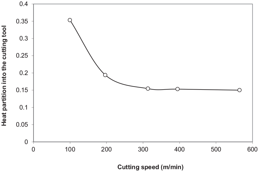
Variation of average heat partition into the cutting tool (RT) with cutting speed.
Conclusion
In this study, an analytical thermal modelling approach which considered the combined effect of primary and secondary heat sources on temperature rise is employed for accurate estimation of heat partition into the cutting tool for orthogonal machining of AISI/SAE 4140 high-strength alloy steel with carbide cutting tools. The thermal model presented in this study applies a non-uniform frictional heat intensity based on a quantitative determination of sticking and sliding contact lengths at the tool-chip interface through EDXA material transfer analysis. The temperature rise in the chip due to primary and secondary heat sources matched with the temperature rise in cutting tool due to non-uniform frictional heat source at the tool-chip interface leads to the solution of non-uniform heat partition into the cutting tool by solving a set of linear equations through programming in MATLAB®. The thermal model was validated by matching the average predicted cutting temperatures with the experimentally measured tool-chip interface temperatures. The relative differences between the average tool-chip interface temperature values predicted by the thermal model and those measured in the experiments through IR thermal imaging camera are within −0.8% to 6.3%. Hence, the presented thermal model proves its ability to predict cutting temperatures at the tool-chip interface. The average heat partition into the cutting tool (RT) varies from 35% down to 15% for the complete range of cutting speeds. Thus, this research study strengthens the integrity and dominant contribution of the combined effect of primary and secondary heat sources on temperature rise in the prediction of heat partition into the cutting tool.
Footnotes
Acknowledgements
The authors sincerely thank Dr. Muhammad Aslam Sheikh retired as a Reader from The University of Manchester, UK, for his critical discussion on experimental and modelling results and reading during manuscript preparation.
Author contributions
FA was in charge of the whole trial. MA wrote the manuscript and assisted with the process of analysis. Both authors read and approved the final manuscript.
Declaration of conflicting interests
The author(s) declared no potential conflicts of interest with respect to the research, authorship, and/or publication of this article.
Funding
The author(s) received no financial support for the research, authorship, and/or publication of this article.
Availability of data and materials
All data generated and analyzed during this research work are included in this published article.