
Abstract
Mechanical and microstructural properties of titanium alloys change with β-phase fraction. This in turn influences the dominant tool wear mechanisms in their machining. This work therefore involves turning experimentation on three titanium alloys with varying β-phase fraction, namely, α, α+β and β-rich alloys using coated carbide tools, to identify dominant wear mechanisms, which hitherto have not been adequately investigated. The dominant wear mechanisms were investigated using scanning electron microscopy and energy-dispersive X-ray analysis of worn tool surfaces and were also correlated with the cutting forces during machining. Abrasion, abrasion with built-up edge and plastic deformation of cutting edge appeared to be the dominant tool wear mechanisms in α, α+β and β-rich alloy, respectively. At the same time, diffusion of Sn, V and Mo from α, α+β and β-rich alloys to tool face, respectively, was observed. The chip–tool contact length predicted using the analytical models from the literature matched closely with the experimental values.
Introduction
Titanium alloys have a two-phase (α-hexagonal close-packed (HCP) and β-body-centered cubic (BCC) microstructure at room temperature. A change in β-phase fraction in titanium alloy can lead to significant changes in the mechanical properties and microstructure of titanium alloys. The change in β-phase fraction also changes the shear band forming tendency and the corresponding segmentation frequency during machining of these alloys. Consequently, the mechanism of tool wear would differ with a change in β-phase fraction in titanium alloy. It is envisaged that an investigation into the identification of dominant tool wear mechanism would help design appropriate cutting tools and lubrication systems for machining of the titanium alloys.
In titanium alloys, the percentage of α and β phases at room temperature can be changed with the help of different alloying elements. Higher contents of α stabilizer alloying element, namely, Al, Sn, O and so on, increase the proportion of α phase at room temperature. Similarly, a higher proportion of β stabilizer element, namely, V, W and Mo, increases the proportion of β phase in titanium alloys at room temperature. Figure 1 illustrates three different titanium alloys and their approximate place on β isomorphous phase diagram obtained by changing the alloying elements. It may be noted that the β phase is more ductile and has more number of slip systems available than α phase. Therefore, titanium alloys with higher proportion of β phase are easier to process thermo-mechanically than those containing higher proportion of α phase. Consequently, they affect the tool wear during machining. This study focuses on the influence of β phase fraction on the mechanism of tool wear.
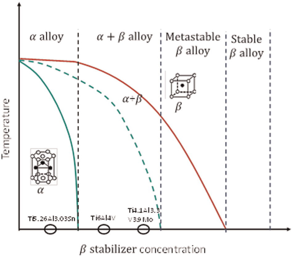
β Isomorphous phase diagram showing approximate position of analyzed titanium alloys.
Numerous researchers have worked on machining of titanium alloys to identify wear mechanisms while machining with different tool materials. While machining titanium alloys with high-speed steel (HSS) and cemented carbide tools, excessive cratering and deformation at the nose were identified as predominant tool wear mechanisms. However, with a composite tool containing wurtzite boron nitride-cubic boron nitride composite (wBN-cBN), which has high fracture toughness and hardness, tool wear was found to be due to diffusion–dissolution.
1
Maximum flank face wear and excessive chipping at the cutting edge were identified as major tool wear mechanisms in machining of Ti-6246 with cemented carbide tools. Also, it was observed that the cemented carbide inserts with finer grain size and honed cutting edge show longer tool life than coarse-grain carbides in machining of titanium alloys.
2
Face milling of Ti6Al4V shows chipping on rake face as a dominant tool wear mechanism. Furthermore, it was evident that chemical vapor deposition (CVD)–coated tungsten carbide inserts outperformed physical vapor deposition (PVD)–coated inserts due to their strong adhesion property.
3
If the machining temperature reaches above 700 °C, an excessive diffusion wear in machining
A summary of tool wear mechanisms that prevail in machining of various titanium alloys is presented in Table 1. It is observed that several tool wear mechanisms9,10 play a role in the degradation of cutting tools while machining titanium alloys.
Tool wear mechanisms in machining of titanium alloys.
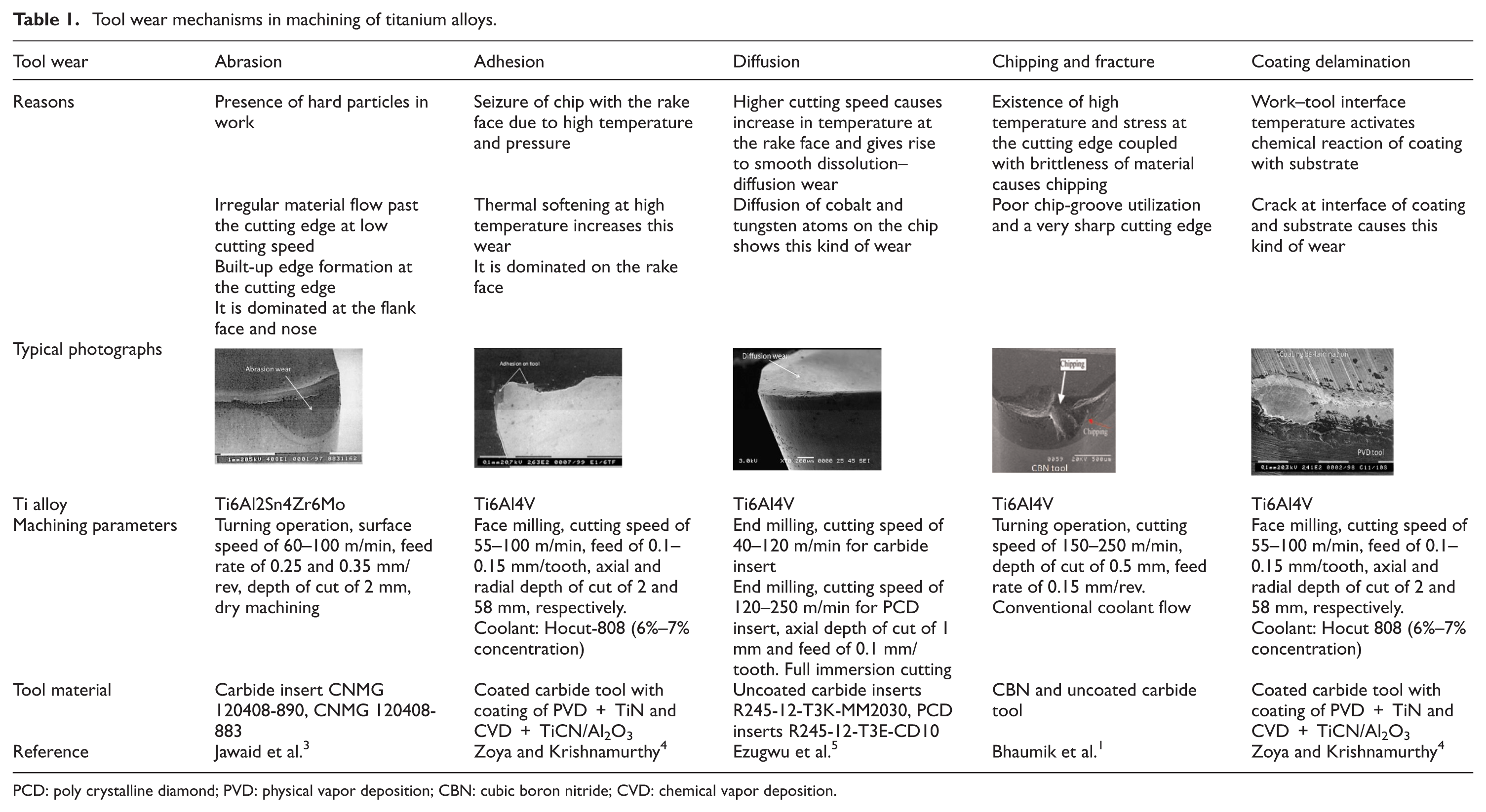
PCD: poly crystalline diamond; PVD: physical vapor deposition; CBN: cubic boron nitride; CVD: chemical vapor deposition.
It is apparent from the literature reviewed that the tool wear mechanisms change with cutting tool materials and machining processes. Very few studies have concentrated on the influence of work material properties on the tool wear mechanism. Titanium alloys with a change in β-phase fraction differ widely in microstructure and mechanical properties. Therefore, the tool is subjected to a variation in the magnitude of cutting forces. Also, microstructure of titanium alloy changes from coarse-grain equiaxed to fine-grain lamellar. Therefore, identifying a dominant tool wear mechanism in each of the titanium alloys will enable appropriate selection of tool materials, coolants and lubrication methods and tool geometry, thereby helping in minimizing the tool wear rate.
Therefore, machining experiments were carried out on three types of titanium alloys. To analyze the mechanism of tool wear, scanning electron microscopy (SEM) and an energy-dispersive X-ray analysis (EDAX) were performed on the worn-out face and flank surfaces of the worn cutting tools.
Theme of experiment
Figure 2(a) shows the theme of this work. The mechanical properties of titanium alloys differ significantly with their composition and so are their interactions with cutting tools during machining. Therefore, in this work, three titanium alloys, that is, α,
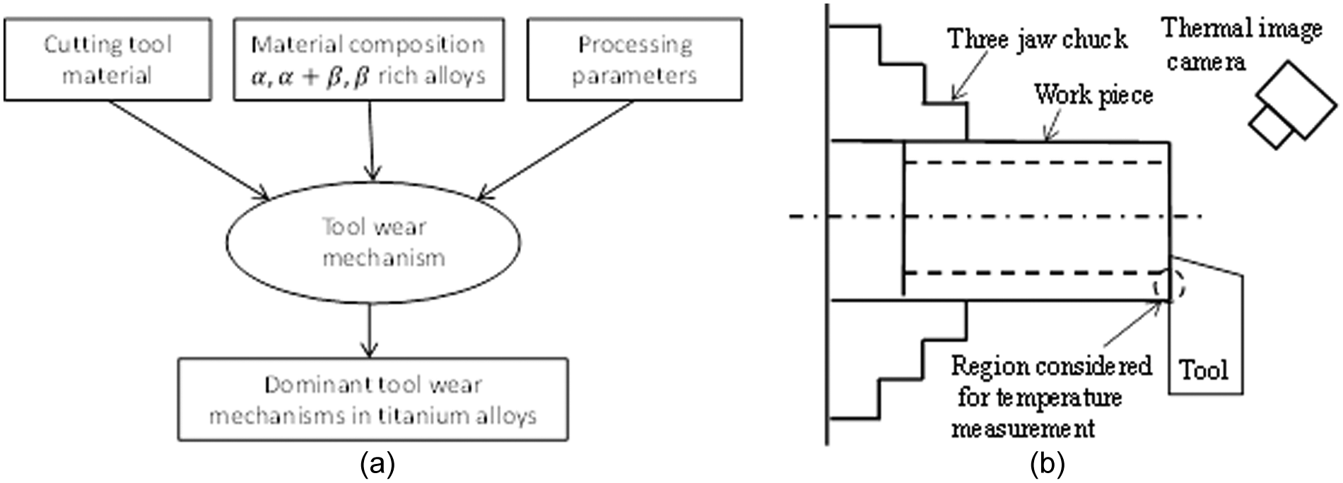
Plan of experiment: (a) theme of the experiment and (b) experimental setup.
Experimental specifications
Experimental specifications including details on alloy compositions, their hardness, machines and tools, processing parameters and response variables used in this work are presented in Table 2. In order to get insight into the mechanical properties of the three titanium alloys, hardness of the alloys was measured with a nano indenter. An average of the measured hardness values is given in Table 2. From Table 2, it is observed that the hardness of β-rich alloy was the highest and that of α alloy was the lowest.
Experimental specifications.
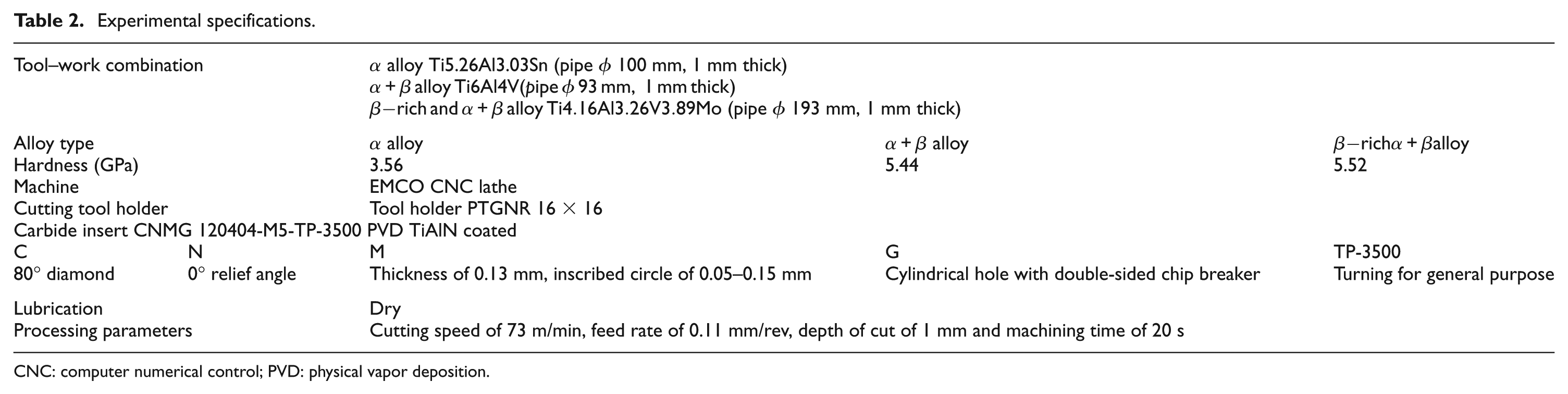
CNC: computer numerical control; PVD: physical vapor deposition.
Experimental procedure
The orthogonal turning experiments were carried out on a computer numerical control (CNC) lathe as per the specifications given in Table 2. A new carbide insert edge was used for machining each titanium alloy. Although the workpieces of different diameters were used in the experiments, the cutting speed and feed rate were maintained at 73 m/min and 0.11 mm/rev, respectively. The machining duration was kept 20 s for the three titanium alloys. All the tests were repeated once. Cutting forces during machining were measured using the piezoelectric Kistler dynamometers. The worn-out inserts were examined under SEM. Also, EDAX was performed on the cutting tool surfaces to identify the diffusion of alloying elements from work surface to the tool face. Temperature during machining was measured using thermal image camera FLIR P640 at 30 Hz that has a spatial resolution of 640 × 480 pixels.
Also, several orthogonal machining experiments on each of the three alloys were done to obtain chip roots using a quick-stop device. This device withdraws the cutting tool instantaneously leaving a partially formed chip on the work surfaces. The roots thus obtained were examined under SEM to obtain various parameters such as shear angle, chip segment pitch and chip compression factor that are required to evaluate chip–tool contact length.
Results and discussion
In this section, results of experiments described in the previous section are presented. SEM images of the worn-out surfaces and cutting edges of tools were analyzed to identify tool wear mechanisms operating during machining of each titanium alloy. The results of an EDAX on worn-out cutting edge show the diffusion of various alloying element from a titanium alloy to the insert face. A pattern of cutting and feed forces during machining of the three titanium alloys has been correlated with the mechanisms of tool wear. Finally, chip–tool contact length was evaluated using various analytical models, and the results are compared with those obtained from this experimental work.
Temperature at cutting zone
The temperature reached during machining has a profound effect on tool wear mechanism. A higher temperature at the cutting zone softens the tool and accelerates its wear. In this experiment, maximum temperature reached during machining operation is recorded and thermal images of this are shown in Figure 3(a)–(c). It is known that a thermal image camera gives an overall temperature of the cutting zone, which may not represent the exact temperature of tool–work or tool–chip interface. Therefore, the recorded temperature by this method is considered to be the overall temperature of the cutting zone.
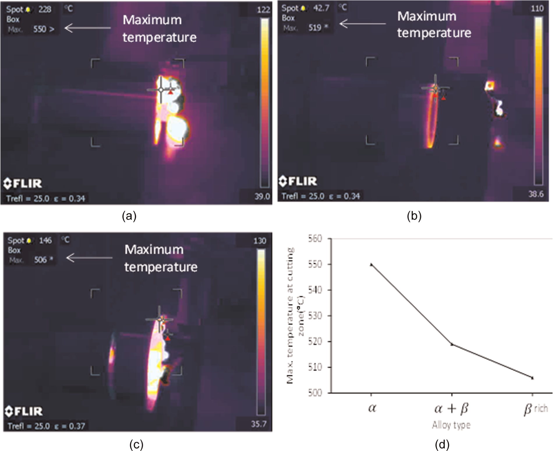
Thermal image of maximum temperature reached during machining: (a) α alloy, (b)
In α alloy, temperature of the cutting zone exceeds 550 °C during machining (see Figure 3(a)). In
Tool wear in α alloy
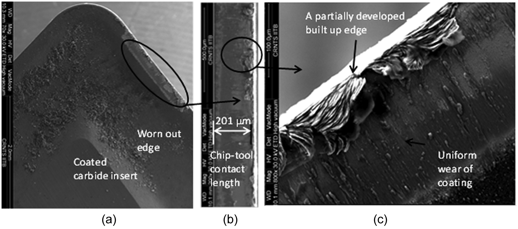
Figure 4(a)–(c) shows SEM images of the rake face of the tool used in machining α alloy. The worn-out cutting edge of tool shows some wear mechanisms in machining of α titanium alloy. A magnified image of the tool face in Figure 4(a) is shown in Figure 4(b) and (c). Appearance of rough surface on the tool face shows that material from the cutting edge has been peeled off nonuniformly and there is no sign of adherence of chip material on the tool face (see Figure 4(c)). The tool face appears to be rough and delamination of coating material appears to be caused due to rubbing of chips over it. Therefore, in machining α alloy, tool coating appears to be less effective in minimizing tool wear. Also, no plastic deformation on the cutting edge is observed. This may be due to low hardness of α alloys. The chip–tool contact length on the rake face has been measured from the magnified SEM image of cutting edge of insert, as shown in Figure 4(b), which is about 201 µm.
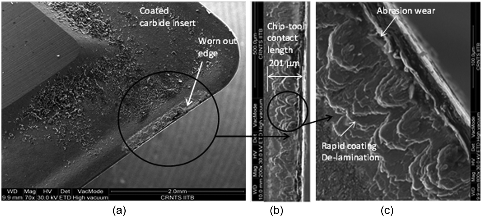
SEM image of worn-out tool face and cutting edge used to machine α alloys: (a) insert, (b) magnified image of insert showing chip–tool contact length and (c) mechanism of tool wear.
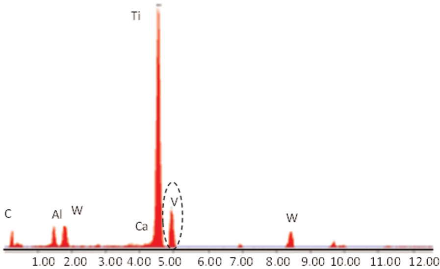
EDAX of the material on the tool face shows the presence of Sn on the worn edge. By ignoring the presence of Ti and Al, which are the part of coating, the presence of Sn confirms its diffusion from the workpiece on to the tool face (see Table 3 and Figure 5).
Element analysis of worn-out edge.
Note: Sn, V, Mo are significant alloying elements of rich alloy, which are diffused on the worn out cutting edge of insert.
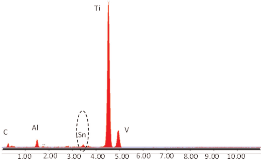
Element analysis at the cutting edge by EDAX in machining α alloy.
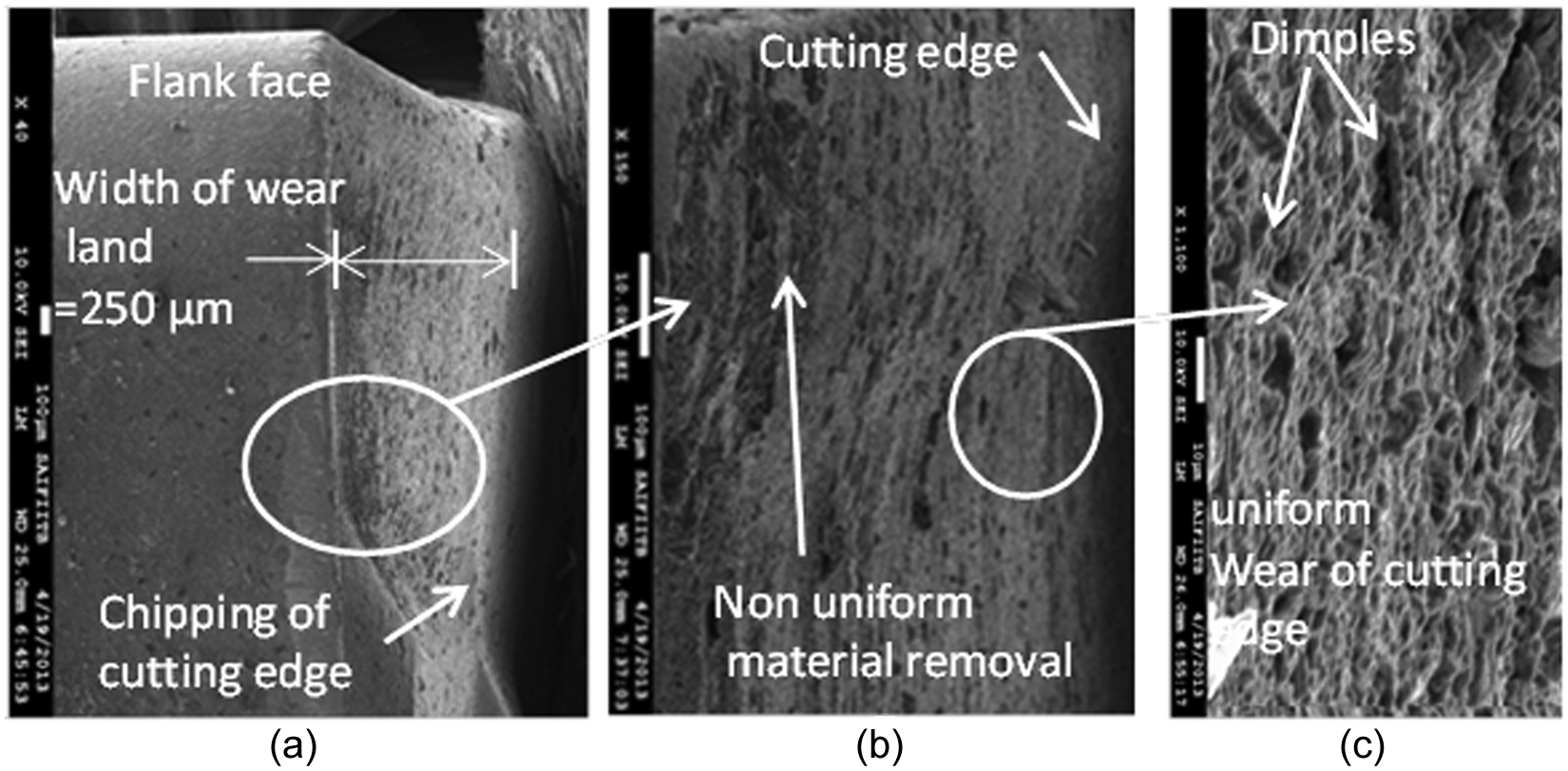
Similar to rake face, flank face of the insert has also been observed under SEM. Figure 6(a)–(c) shows SEM images of the flank face at various magnifications that illustrate the wear pattern on inserts. Chipping of the cutting edge is observed during machining of α alloy (see Figure 6(a)). The material on the flank face away from the cutting edge is being removed. Also, SEM image of the cutting edge at very high magnification shows a nonuniform wear (see Figure 6(b)) and a further enlarged view in Figure 6(c). The width of wear land measured is 109 µm (see Figure 6(a)). Thus, in machining α alloy, wear mechanisms prevalent on the flank face are chipping and nonuniform abrasive wear of the surface.
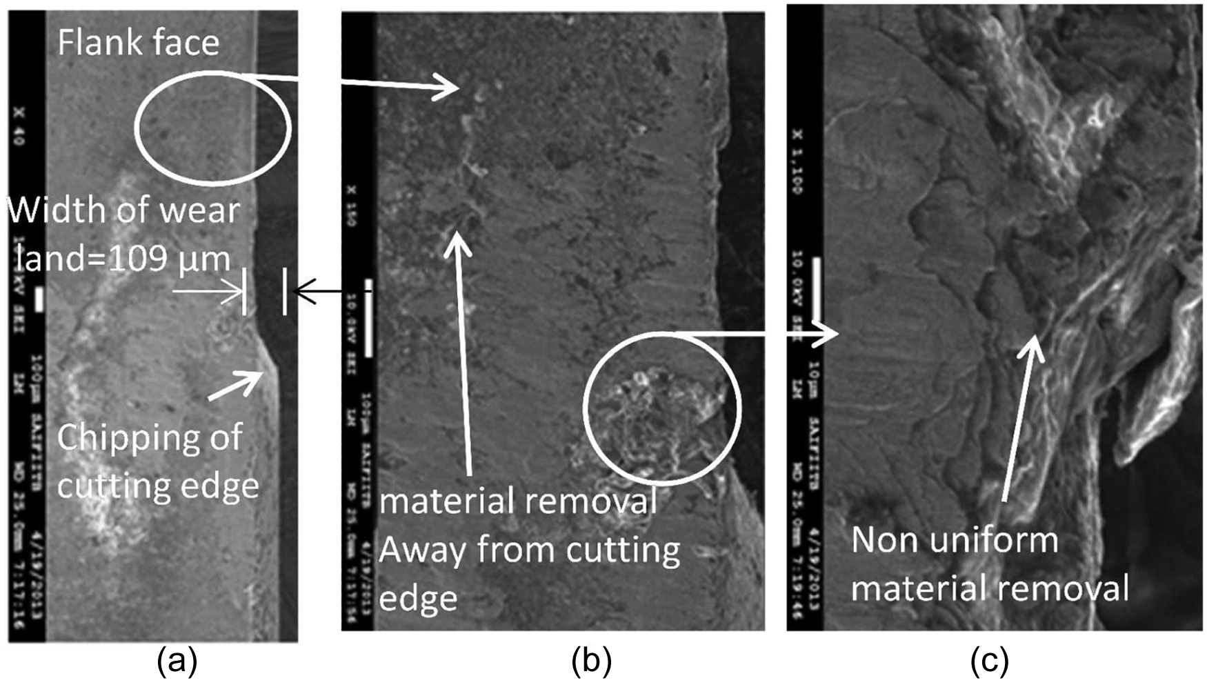
Flank face of worn-out insert in machining α alloy: (a) insert edge and surface at flank, (b) magnified image of flank surface and (c) magnified image of cutting edge.
Tool wear in
alloy
SEM images of a worn-out insert used in machining of
SEM image of worn-out face and cutting edge used to machine
EDAX shows the presence of vanadium on the worn-out tool edge (see Table 3 and Figure 8). By ignoring the presence of Ti and Al, which are a part of coating, the presence of vanadium at the cutting edge shows its diffusion on the tool face. This is because vanadium is a significant alloying element in
Element analysis at the cutting edge by EDAX in machining
The wear pattern on the flank face shows features that are similar to that on the rake face. In
Flank face of worn-out insert in machining
Tool wear in β-rich alloy
SEM images of worn-out insert used to machine β-rich titanium alloy are shown in Figure 10(a)–(c). While the cutting edge appears to be intact over most of its length, a small portion of it shows discontinuity, probably due to deformation or fracture of cutting edge (see Figure 10(b) and (c)). This could be due to high temperature of around 506 °C recorded by the thermal camera during machining and higher material hardness (55% higher than α alloy) (see Figure 3(c)). A small contact of the chip over the cutting edge gives rise to high pressure and temperature, which softens the cutting edge material. This affects the integrity of edge due to deformation of the insert material. No adherence of work material on the face of the tool or the cutting edge is observed. A color change along the width of worn-out edge shows removal of coating. However, the planer surface near the cutting edge shows slow rate of coating delamination, which underlines the effectiveness of coating in machining of β-rich alloys. Also, there is no sign of built-up edge formation on the cutting edge along the tool face. Due to deformation of cutting edge, both rake and flank faces get affected. The measured chip–tool contact length from SEM image on the face of insert is 210 µm (see Figure 10(b)).
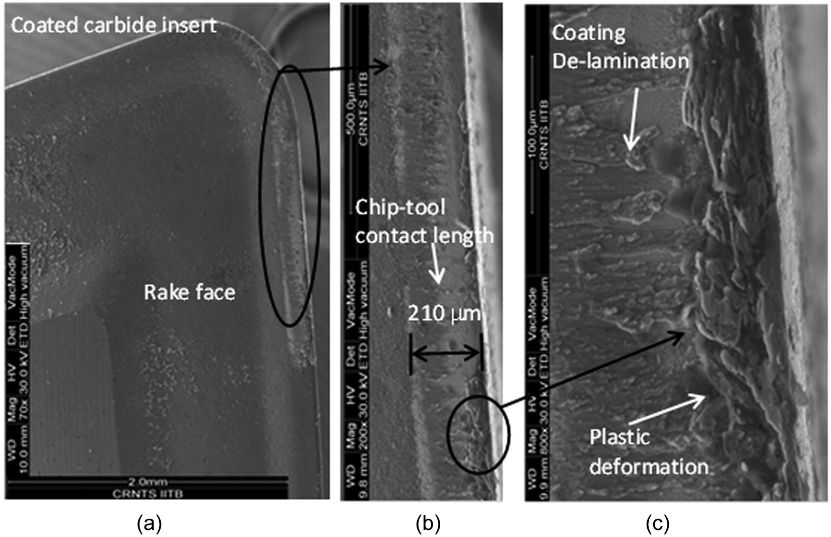
SEM image of worn-out face and cutting edge used to machine β-rich
EDAX on the tool face shows the presence of Mo on the worn-out tool face (see Table 3 and Figure 11). Ignoring the presence of Ti and Al, which are a part of tool coating, diffusion of Mo, which is a significant alloying element of the work material, is confirmed on tool face.
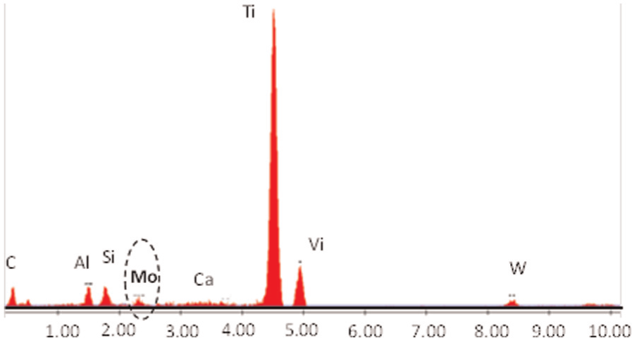
Element analysis with EDAX at the cutting edge of β-rich alloy.
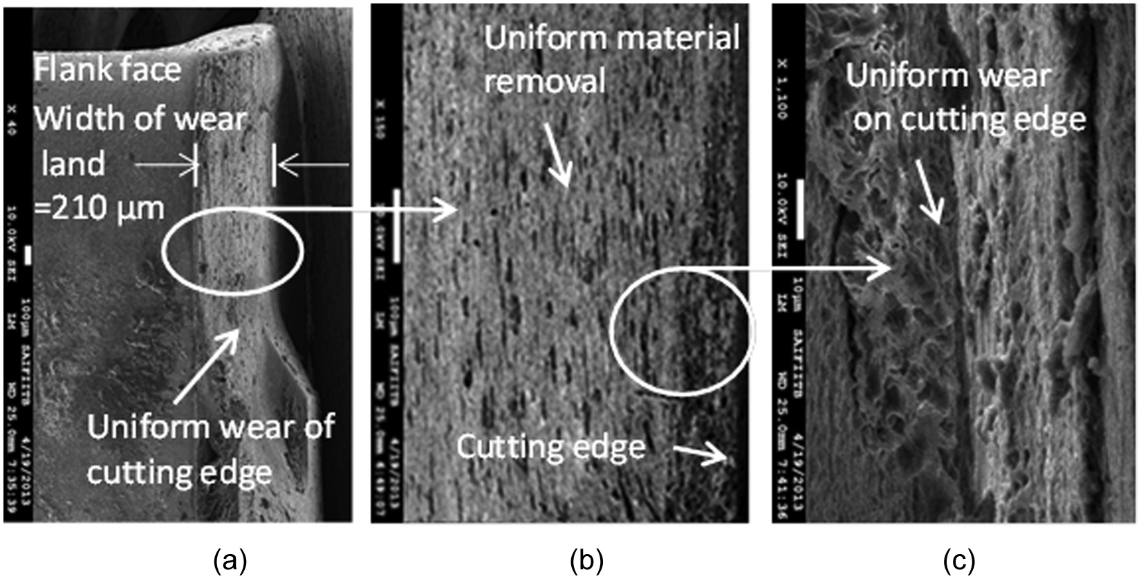
Figure 12(a)–(c) shows flank wear pattern on a worn-out insert during machining β-rich titanium alloy. Here, chipping at the cutting edge is observed (see Figure 12(a)). Also, tool material appears to be removed nonuniformly from the flank face during machining (see Figure 12(b)). However, the material at the cutting edge is removed uniformly (see Figure 12(c)). Dimples at the cutting edge show sudden fracture on the cutting edge (see Figure 12(c)). The width of flank wear land measured is 250 µm (see Figure 12(a)). Larger width of flank wear land (250 µm) over the chip–tool contact length points to flank wear as a dominant mode of tool wear in machining β-rich titanium alloy.
Flank face of worn-out insert in machining β-rich alloy: (a) insert edge and flank surface, (b) magnified image of flank surface and (c) magnified image of cutting edge.
Correlation between machining forces and tool wear
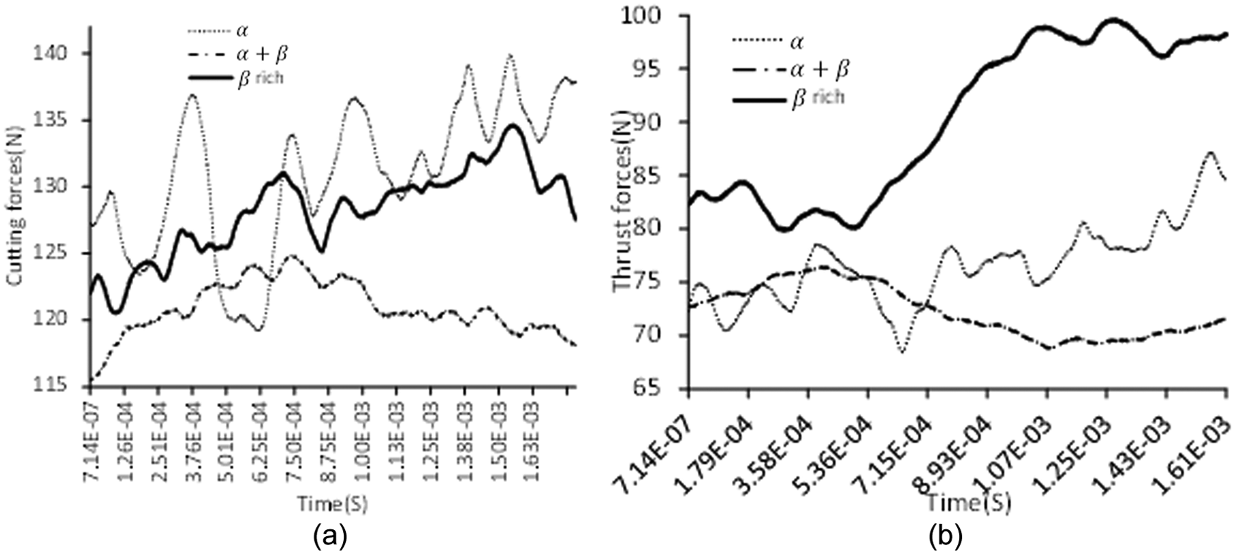
An attempt has been made to correlate pattern of variation in the cutting and thrust forces and the predominant tool wear mechanism in machining of the three titanium alloys. Figure 13(a) and (b) illustrates a representative pattern of cutting forces obtained using dynamometers in machining of the three titanium alloys.
Pattern of (a) cutting force and (b) thrust force in orthogonal machining of the three titanium alloys.
In α alloy, the magnitude of cutting forces (130 N) and fluctuation in their magnitude, from 119 to 136 N, appears to be the highest (see Figure 13(a)). On the other hand, in the case of
A change in the pattern of cutting force can be further explained from the chip microstructure of the three titanium alloys, as shown in Figure 14(a)–(c). In α alloy, segments are formed predominantly by thermal softening that leads to formation of shear bands (see Figure 14(a)). Also, grains outside the shear band appear deformed. Due to this, a large reduction in the cutting force was observed during its machining. In
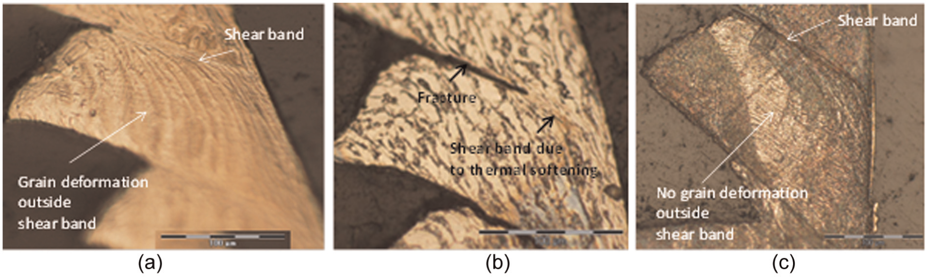
Chip microstructure of the three titanium alloys: (a) α alloy, (b)
Figure 13(b) shows a variation in the thrust forces. In this case, the highest magnitude of thrust force is observed during machining of β-rich alloys. In α alloy, similar to cutting forces, thrust forces have higher intensity of fluctuation. Hence, the β-rich alloy shows uniform thrust forces. It is observed that this pattern of machining forces reflects the dominant tool wear mechanism for the three titanium alloys. In α alloy, due to higher magnitude and intensity of fluctuation in the cutting forces, continuous contact at the cutting edge of the tool and workpiece occurs for a smaller period of time. This reduces the possibility of formation of built-up edge. However, the higher fluctuation in machining forces causes an early coating delamination and abrasion wear on the rake face. This is evident from the SEM images of inserts used for machining of α alloy, as shown in Figure 4(a)–(c).
In the case of
In the case of β-rich alloy, the higher magnitude of cutting forces introduces deformation on some portions of the cutting edge. This is evident from the SEM image of worn-out insert shown in Figure 10(a)–(c). Also, a higher magnitude of thrust forces causes chipping of the cutting edge, as shown in Figure 12(a). As compared to α and
Evaluation of average chip–tool contact length
Chip slides over the rake face of tool. The contact length of the chip with rake face is called chip–tool contact length. This length determines the friction between the chip and the rake face. Also, the maximum temperature reached during machining occurs in this region. Therefore, this value is useful in designing cutting tool geometry, and it determines cutting forces and the rise of temperature during machining.9,13 A smaller chip–tool contact length ensures less friction and lowers temperature at chip–tool interface and reduces the quantity of heat transferred to the tool. In this work, the chip–tool contact length has been evaluated using various analytical models and compared with the experimentally observed values in machining of the three titanium alloys. The experimental values of chip–tool contact length were measured from SEM images of worn-out inserts. Figures 4(b), 7(b) and 10(b) show chip–tool contact length on the rake face while machining α,
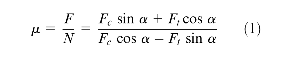
where µ is average coefficient of friction, F is tangential component of resultant force along the rake face, N is normal component of resultant force, Fc is cutting force, Ft is thrust force and α is rake angle of the tool of 0° for the insert used in the experiment. The average cutting and thrust force measured using dynamometer and friction coefficient evaluated by putting these values in equation (1) are given in Table 4.
Machining forces and friction coefficient.
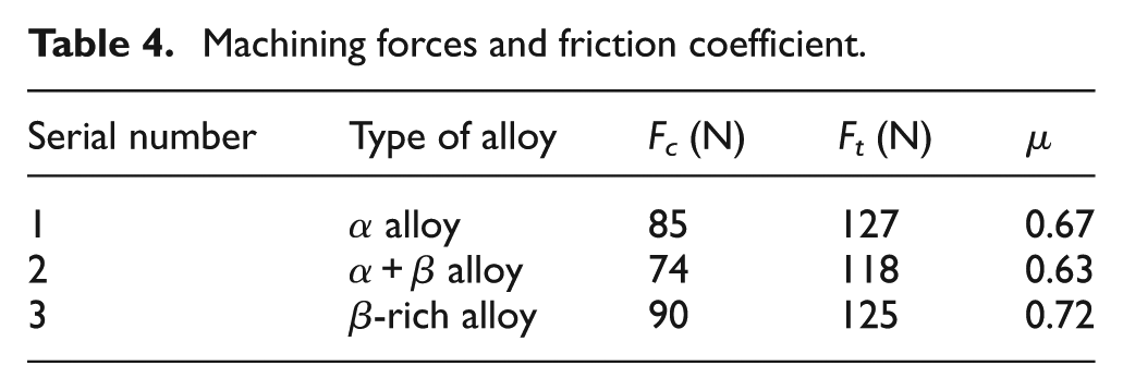
The coefficients of friction evaluated are 0.67 for α alloy, 0.63 for
Average chip–tool contact length evaluated using experimental and various analytical models.
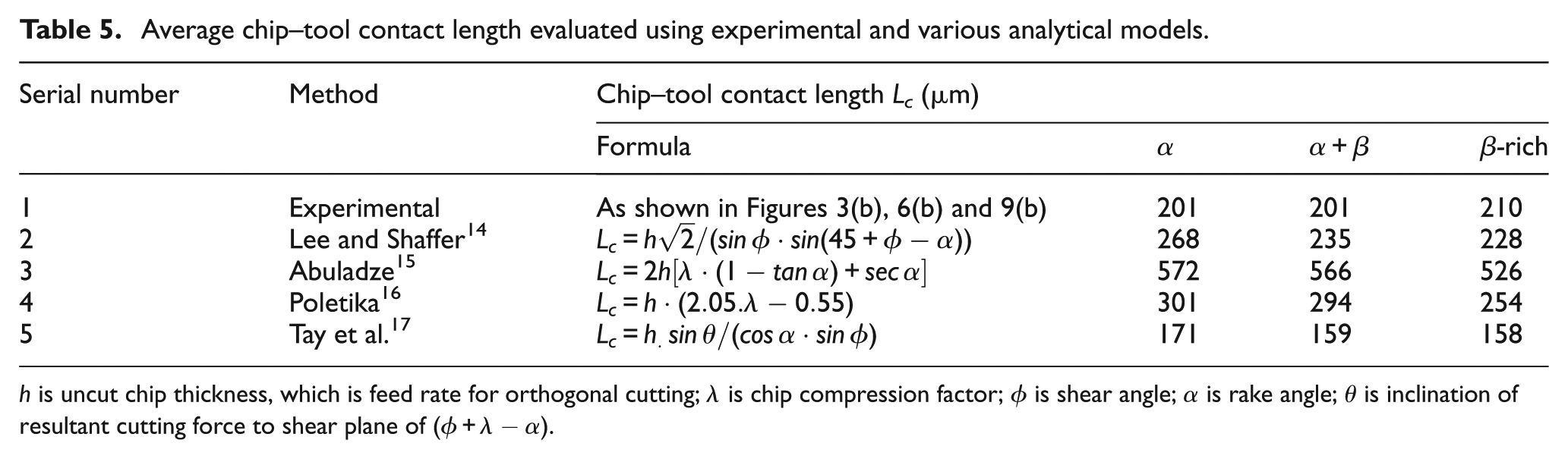
h is uncut chip thickness, which is feed rate for orthogonal cutting; λ is chip compression factor; ϕ is shear angle; α is rake angle; θ is inclination of resultant cutting force to shear plane of
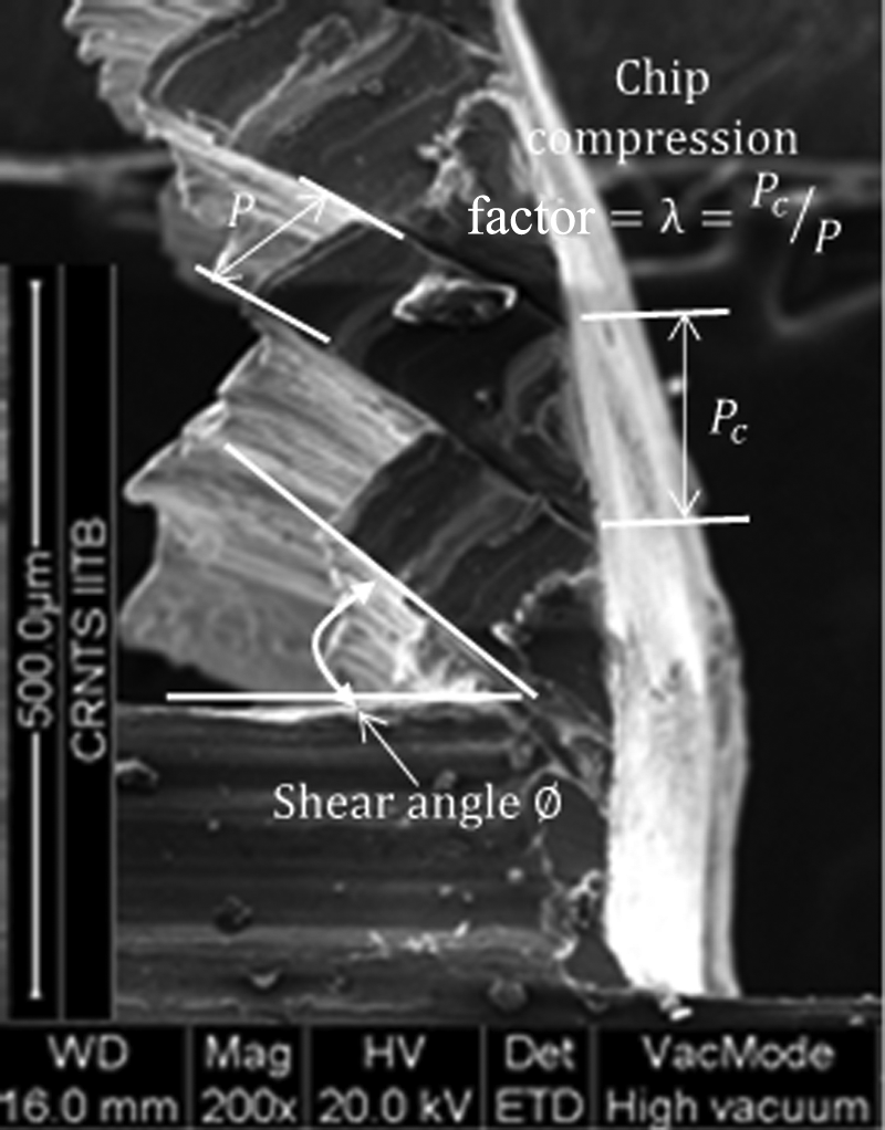
Method to evaluate shear angle and chip compression ratio.
The chip–tool contact length calculated using the models and their comparison with the experimental values are presented in Figure 16. It may be noted that the results obtained with Lee and Shaffer’s 14 model and Tay et al.’s 17 model match closely with the experimental values. While the Lee and Shaffer’s model overestimates average chip–tool contact length, Tay et al.’s model underestimates it. The average chip–tool contact lengths predicted with Lee and Shaffer’s model are based on the shear angle. In this work, the shear angle is determined from the analysis of chip roots (Figure 15). A typical calculation involved in the evaluation of chip–tool contact length is presented in Appendix 1. It is envisaged that since Lee and Shaffer’s model incorporates shear angle, the model gives prediction closer to the experimental values. Similarly, Tay et al.’s model too involves shear angle beside friction angle. In this work, both these angles are obtained from the experimental data. Again, the prediction of the chip–tool contact length from this model appears to be close to the experimental values, although the values are underestimated. On the other hand, Abuladze’s 15 model uses chip compression ratio to evaluate chip–tool contact length. The inaccuracy in determination of this ratio, particularly for the segmented chips, introduces a large margin of error in the prediction of chip–tool contact length. Poletika’s 16 model is primarily an empirical model. Hence, it requires specific constants. As the constants could not be evaluated for the alloys used in this work, the evaluation of chip–tool contact length with this model lies away from the experimental data.
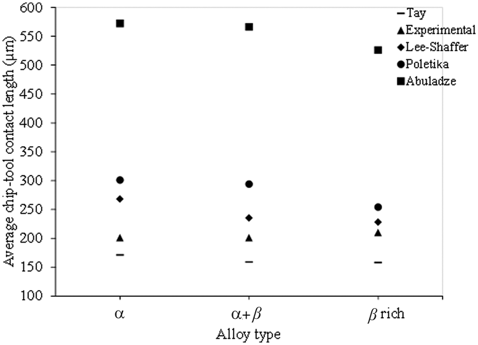
A comparison between experimental and analytically predicted chip–tool contact length.
Comparative evaluation of tool wear criteria
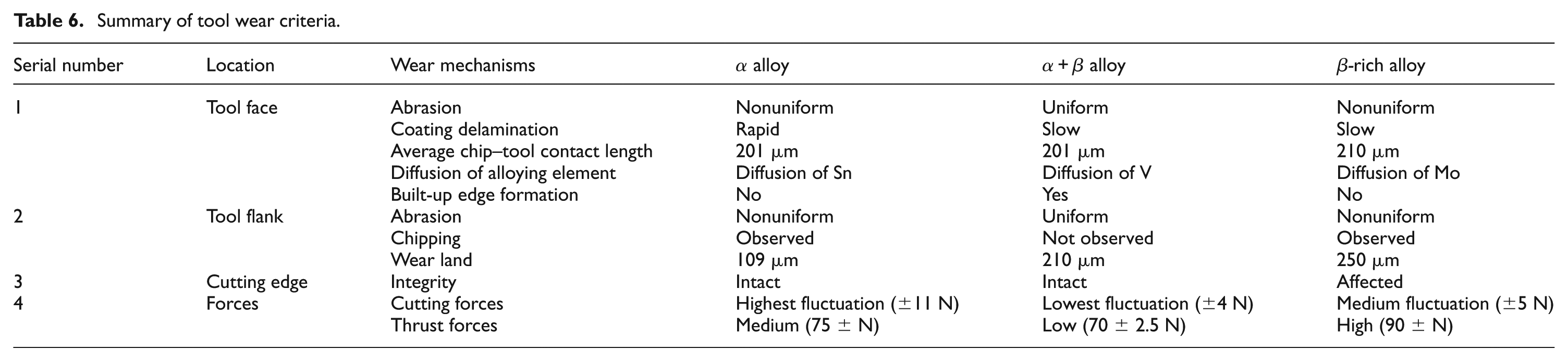
Table 6 summarizes a comparative evaluation of different tool wear criteria observed in three titanium alloys. In α- and β-rich alloys, a nonuniform abrasion on the tool face and flank was observed. In
Summary of tool wear criteria.
Conclusion
Based on the discussions of the experimental results, the following conclusions are drawn:
Machining of α alloy involves a higher magnitude of cutting forces and a higher intensity of fluctuation in the machining forces. Therefore, in the machining of α titanium alloy, delamination of coating occurs early. Thus, coating on the tool is relatively less effective in machining α alloy.
A uniform cutting and thrust forces were observed during machining of
In the case of β-rich alloys, a higher magnitude of thrust forces was observed during machining. Therefore, machining β-rich alloy shows the deformation on some portion of the cutting edge. The damage to cutting edge causes both the face and the flank wear during machining operation. The coating delaminates at a lower rate while machining this alloy. Therefore, tool coating will help in improving the tool performance in machining of this titanium alloy.
Diffusion of major alloying element such as Sn from α alloy, V from
The chip–tool contact length measured from SEM images was almost the same in the case of α and
Footnotes
Appendix 1
The average chip–tool contact length is evaluated analytically with Lee and Shaffer’s, Abuladze’s, Poletika’s and Tay et al.’s models. Various parameters used for the evaluation are determined from the experiments. A sample calculation showing evaluation of chip–tool contact length, Lc, using each model is described in the following. These calculations use orthogonal machining data of α alloy at 73 m/min cutting speed and 0.11 mm/rev feed rate.
Acknowledgements
This article is a revised and expanded version of article entitled “Evaluation of Tool Wear Mechanisms in Machining of Three Different Types of Titanium Alloys” presented at the 4th International and 25th AIMTDR Conference, Jadavpur University, Kolkata, 14–16 December 2012.
Declaration of conflicting interests
The authors declare that there are no conflict of interest.
Funding
The authors gratefully acknowledge the partial support provided for this work by the National Centre for Aerospace Innovation and Research—a collaboration of Department of Science and Technology, Government of India; The Boeing Company and IIT Bombay.