
Abstract
A dimensional management procedure is developed and implemented in this work to deal with the identification of the optimum hole diameter that needs to be pre-drilled in order to successfully join two subassemblies in a common hinge line interface when most of the degrees of freedom of each subassembly have already been constrained. Therefore, an appropriate measure is suggested that considers the assembly process and permits the application of optimisation algorithms for the identification of the optimum hole diameter. The complexity of the mechanical subassemblies requires advanced 3D tolerance analysis techniques to be implemented and the matrix method was adopted. The methodology was demonstrated for an industrial, aerospace engineering problem, that is, the assembly of the joined wing configuration of the RACER compound rotorcraft of AIRBUS Helicopter and the necessary tooling needed to build the assembly. The results indicated that hinge line interfaces can be pre-opened at a sufficiently large size and thus, accelerate the assembly process whilst the suggested methodology can be used as a decision-making tool at the design stage of this type of mechanical assembly.
Introduction
Predicting the effect of dimensional and geometric variation in an assembly, due to the inevitable manufacturing and assembly errors, has become an important aspect for the fabrication of high quality products. Any rework or redesign of the product in the production phase can introduce considerable cost. Applied researchers and practitioners have therefore become increasingly interested in quantifying variability in pre-specified product key characteristics early in the design process, before most of the product cost has been committed. For example, in the aerospace industry, 80% of the product cost 1 is dedicated by decisions made at early stages of an engineering project. The importance of dimensional control to reduce assembly variation and thus, the cost in the next generation of civil and military aircrafts has been highlighted in the open literature, for example, in Jeffreys and Leaney. 2
Given the complexity of products in the aerospace and automotive sectors, three-dimensional (3D) tolerance analysis methods have become popular to control and manage variation. 3D tolerance analysis permits to consider dimensional and geometric tolerances as well as their interaction in the 3D space. 3 The majority of the studies completed over the last 30 years have focussed on the development of models to represent and propagate tolerances. According to, 3 typical 3D tolerance techniques are the vector loop method, 4 the matrix method,5,6 the unified Jacobian-Torsor method 7 and the T-map model. 8 Each method has specific benefits and limitations. A comparison of the various 3D tolerance methods can be found in3,9–12 whilst a useful review on the tolerance analysis methods is given in Singh et al. 13 Additionally, computer aided tolerance (CAT) tools 14 have been developed to deal with those types of problem. Moving forward, stream of variation 15 has been introduced to manage and reduce variation in multi-stage manufacturing processes, using state space models to capture variation propagation, as well as various concepts adopted from the control theory and optimisation field.
It is highlighted that, although the development of tolerance analysis methods is an important element in a dimensional management methodology, the appropriate implementation of these methods to analyse real and complex applications is an equally important activity. The complexity of the product and the Assembly Key Characteristics (AKCs) under investigation introduces factors that need to be closely analysed. For example, the establishment of appropriate measures to accurately quantify the predefined AKC and enable the assessment of complex mechanical assemblies. Few works in open literature implement 3D tolerance analysis techniques for the dimensional management of actual aircraft assemblies, which is the main interest of this work. More specifically, a dimensional management methodology was proposed in McKenna et al. 16 to solve over-constrained assemblies, for example, assemblies in which several AKCs 5 compete with each other. Thus, 3D tolerance analysis was performed for a wing spar assembly by implementing the matrix method, whilst a framework was developed to include the cost implications of the selected assembly processes. Vichare et al. 17 in-process assembly measurement information for predicting dimensional variation was suggested. A wing box was analysed whilst CAT simulation models were updated with measurement data to improve the assembly predictions of the product. Therefore, a framework was established by linking several off-the-shelf numerical tools, to implement the suggested dimensional management methodology. Corrado and Polini 18 the statistical tolerance analysis of a tail beam of an aircraft was performed considering the effect of free form surfaces. The commercial software eM-Tolmate of UGS® was used to build the tolerance model and further to carry out Monte Carlo simulation verifying the thickness of the adhesive gap between the mating parts comprising the tail beam. Finally, in Bakker et al. 19 a simplified wing box was analysed using the stream of variation methodology in the frame of a Smart Factory environment. Common to all the listed works is the fact that the AKCs under investigation primarily concerned gaps between mating parts and therefore, simple measures were established to quantify them, for example, the distance between two points or surfaces.
To further the effort of the previous studies, the main focus of this work is to suggest a dimensional management methodology that tackles the problem of projected errors introduced by manufacturing, and assembly errors in the parts or subassemblies to predict the optimum size of a pre-drilled hole at a hinged interface between two sub-assemblies. As presented later in this work, this is a complex, robust optimisation problem to be solved which seeks the Chebyshev centre 20 in the presence of variation. Through valid engineering judgment, the problem is transformed into a typical optimisation problem for which the worst-case scenario is sought. The problem is thoroughly presented in section 2. The suggested dimensional management methodology is developed in section 3 based on homogenous transforms. 21 The formulation of the appropriate AKC to enable the implementation of optimisation techniques is crucial to the proposed methodology. In section 4, the suggested methodology is applied to the RACER joined wing configuration 22 to address the important and novel challenge of successfully building this particular type of assembly. Results and useful conclusions related to the proposed methodology are finally presented in section 5 and 6 respectively.
Problem specification
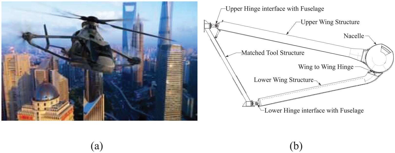
When considering complex products, it is possible to encounter the assembly scenario in which two large subassemblies are built separately before being mounted independently to a primary structure and finally, joined together at a common hinge interface to form the final product (or another larger subassembly). One such aerospace example is the assembly of the joined wing configuration 23 within the novel RACER helicopter, which is the latest generation of compound rotorcraft from AIRBUS Helicopters, as shown in Figure 1. RACER is a prototype compound rotorcraft and thus, only one aircraft set of wings will be produced. Focusing on the example of Figure 1 and without loss of generality, the two wings subassemblies are built separately. 24 Next, they are mounted on a special tool that replicates the wing to fuselage interface, known as the matched tooling. The final product is formed by joining the Upper Wing (UW) and the Lower Wing (LW) subassemblies together on the wing to wing interface in a hinge joint. 24
The critical aspect of this assembly consists of the strict requirements related to the location of the wing to wing interface, with respect to the wing datum reference system, which ensures the successful connection of the two wings. For both wing subassemblies, five out of six degrees of freedom have already been constrained before their final assembly whilst the tolerance associated to the position of the wing to wing interface is generally in the order of hundreds of microns. This, as opposed to a conventional fixed wing assembly, imposes a very difficult constraint to satisfy and hence, to build the wing.
To manage the inevitable manufacturing and assembly errors, the common practice would require the hinge line to be drilled during the final assembly stage when the two wing subassemblies are brought together. However, this practise can introduce critical drawbacks; including, the excessive cycle time of the drilling process, the introduction of significant drilling forces, the elevated temperatures of the drilled parts due to mixed stacks and the additional costs related to the design and manufacture of dedicated tools to ensure the dimensional accuracy of the product whilst being drilled. An appealing alternative to the abovementioned assembly plan would be to pre-drill the mating parts at the component machining stage with an appropriate size of pre-final-size bore. It is clear that the optimum size will be less than the final size of the bore in order to accommodate the various sources of uncertainty but large enough to accelerate the drilling process and avoid some of the listed drawbacks. The main issue, however, is to accurately define the optimum size of the hole to be pre-drilled.
In the general case, there will be a male and female lug mounted on each subassembly respectively whilst their connection is realised by the hinge joint. A simple representation of a generic hinge at a single lug joint in the varied form is depicted in Figure 2(a). For simplicity, only the highlighted portion of the female lug in Figure 2(a) is considered in the analysis. This is because it is assumed that the bore in the second flange of the female lug is controlled, relative to the first, by a few, tight machining tolerances. The sum of these machining tolerances will be significantly smaller than the sum of tolerances effecting the misalignment of the male lug relative to the female lugs. For reference, the overall width across the outside faces of the female lug, that is, the length of bore to be produced, is approximately 42 mm.
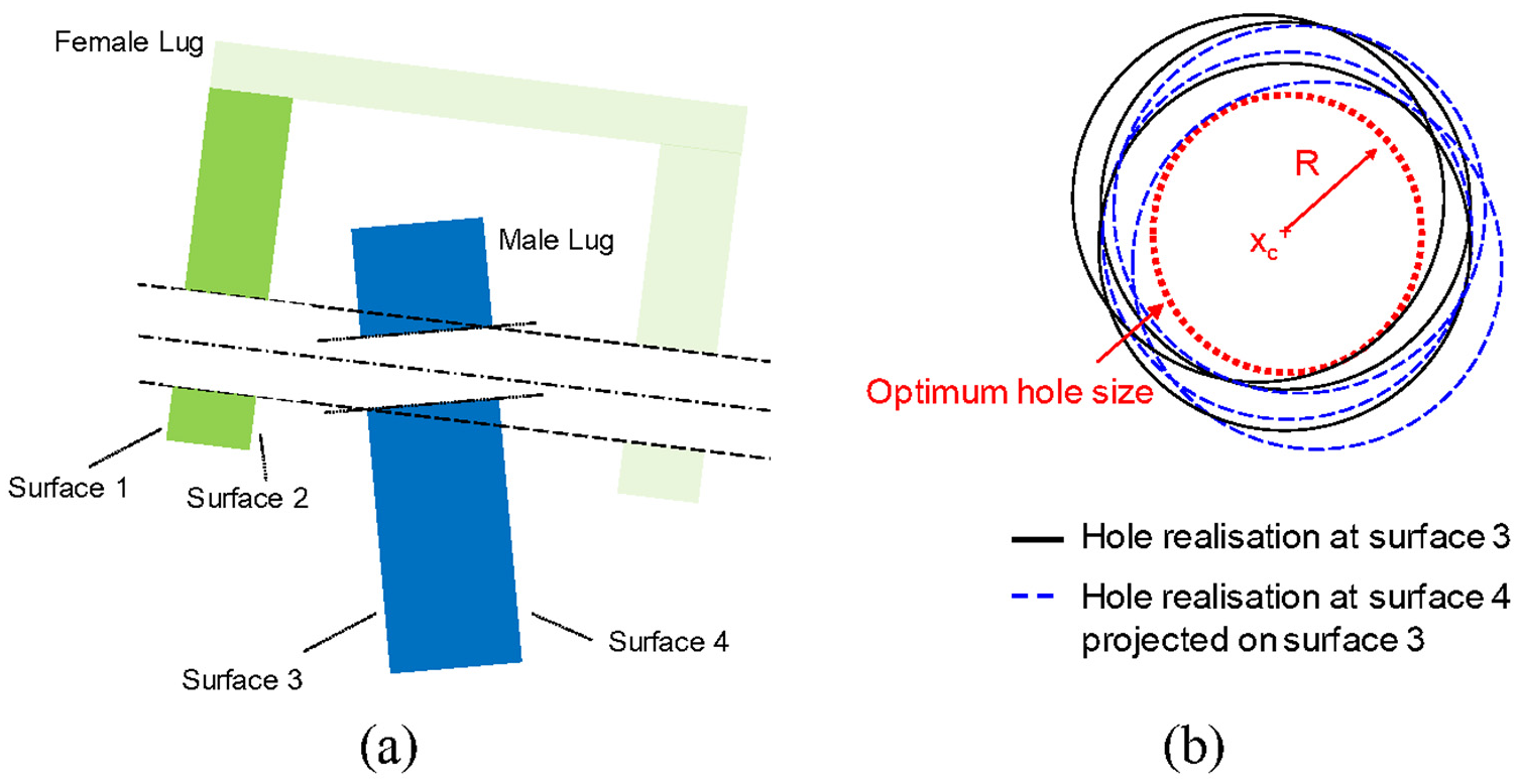
(a) Simplified hinge joint at the varied form and (b) hole realisations due to different assembly varied forms.
The pre-bored hole diameters in both male and female lugs needs to be sufficiently undersized so that a clean hole can be drilled through both parts, regardless of the lug misalignment of the two subassemblies at the final assembly stage. However, two unfavourable scenarios could be encountered. If the hole diameter before boring is too large, the final drilling process may not remove material through the entire length of the hole, as depicted in Figure 3(a). The existence of empty spaces can create wobbling for any inserted pin, increase component wear rates and thus reduce the life of the lug component. The second case is to produce a hole with a smaller diameter, as in Figure 3(b). This means that more material will need to be removed, increasing the assembly duration and the transfer of thermal energy to the structure; which is typically avoided where possible. The optimum size of the hole to be predrilled comprises the AKC of this work and is depicted in Figure 2(a).
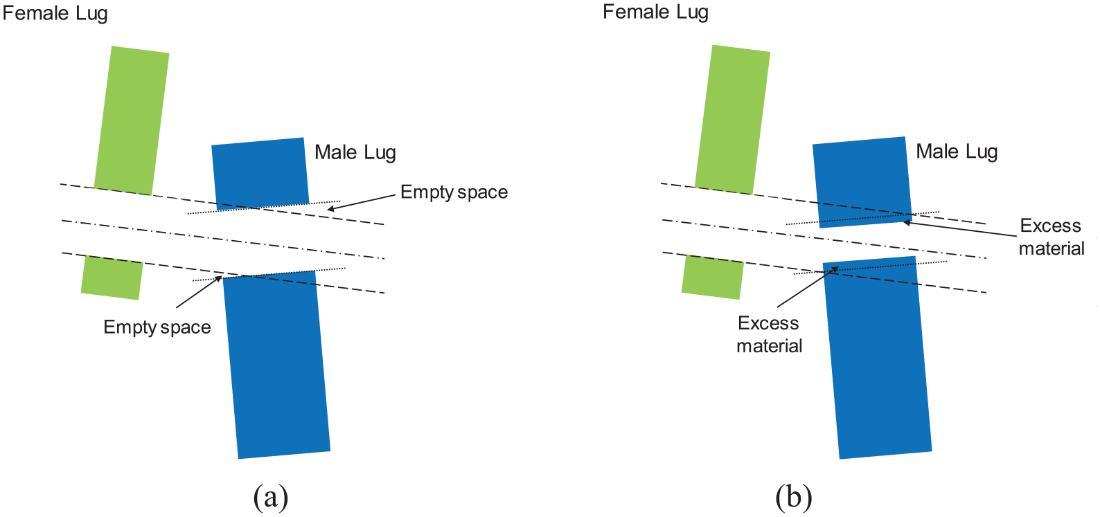
Simplified representation of misaligned male lug showing: (a) oversized and (b) undersized pre-bored hole diameter.
Proposed dimensional management methodology
Quantifying the required size of the pre-bored hole is a complex, 3D problem that is not easily solved using traditional, one or two-dimension tolerance stack-ups. An appropriate measure has to be established to quantify the specified AKC. Therefore tolerance analysis should be applied using a 3D tolerance method. Herein, homogenous transformation matrices (HTM) have been employed to quantify the impact of variation on the objective of this work. 5
Assembly key characteristic
An accurate measure to represent the specified AKC would be to superimpose all of the circles (or ellipses) created at surfaces 3 and 4 from the drilling process in a common plane, for example, on surface 3, for all of the possible permutations of the assembly in the varied form. This is represented in Figure 2(b) for three random realisations. The inscribed circle that stays inside the intersection of all of these circles from the different alignment conditions would give the centre and the diameter of the undersize hinge bore and is presented with the dashed circle in Figure 2(b).
In terms of mathematical modelling, the specific problem can be classified as a geometric optimisation problem. More specifically, it belongs to the centring problem known as the Chebyshev centre problem. 20
That is, let
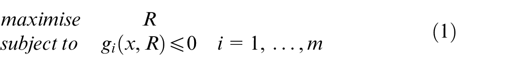
where R is the radius of the inscribed circle;
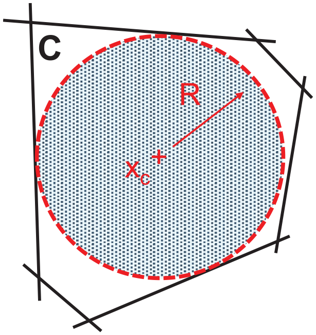
Chebyshev centre of a polyhedron.
In order to circumvent the difficulties and accelerate the calculations, an engineering solution is proposed and the AKC is established by defining an efficient measure, trading reasonable computational effort against the accuracy of the result. The computation of the AKC is simplified by considering the centre of the bore in the male lug to be always as per the nominal position. The proposed measure is defined as the minimum distance of the centre of the bore (at nominal position) to the points forming the intersection of the superimposed circles (or ellipses) on surface 3. A simplified representation of the measure is depicted in Figure 5 and is indicated as
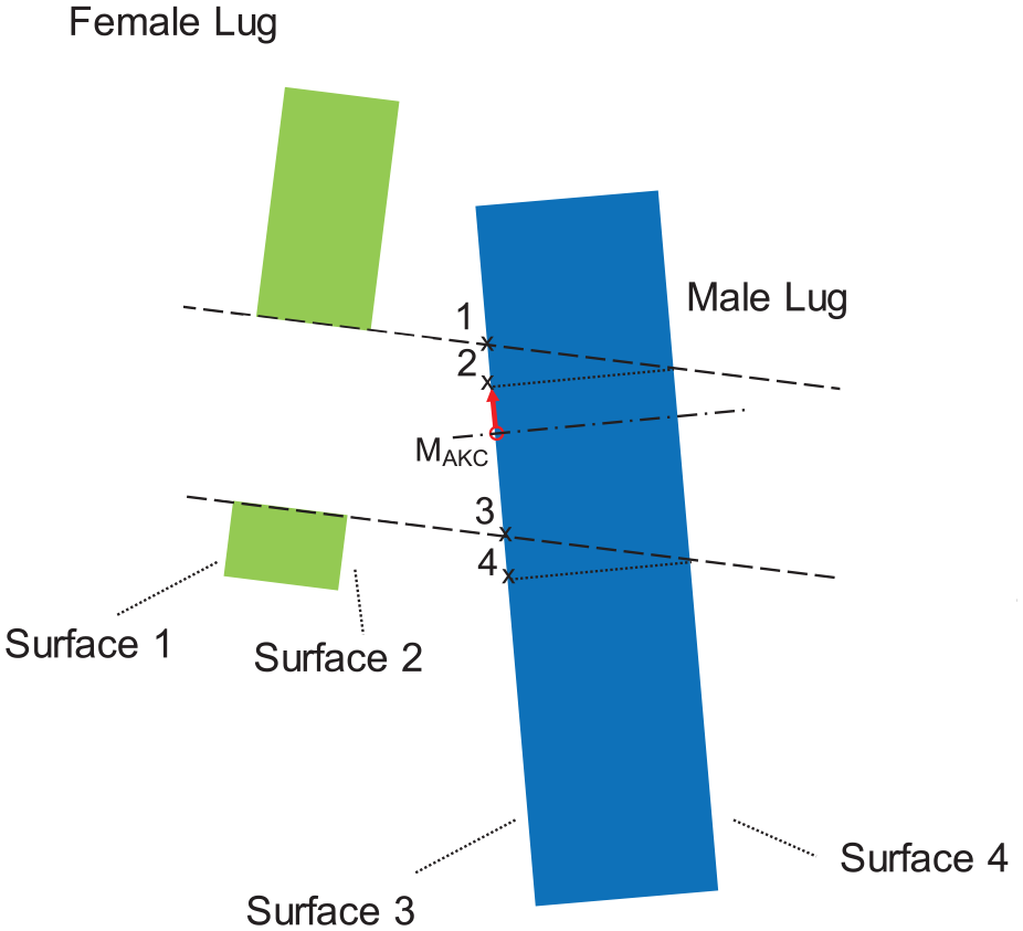
Measure MAKC specification.
The measure
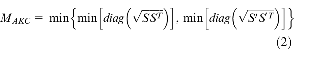
where S and
Matrix method
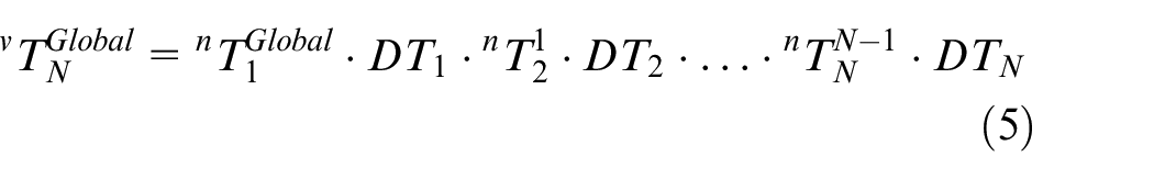
Having specified MAKC, assembly models are developed using homogeneous transforms to calculate this measure. The HTM,
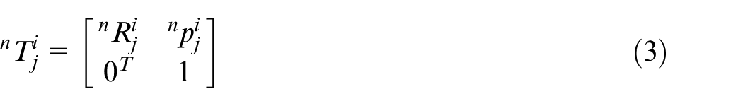
where the leading superscript n indicates nominal form and
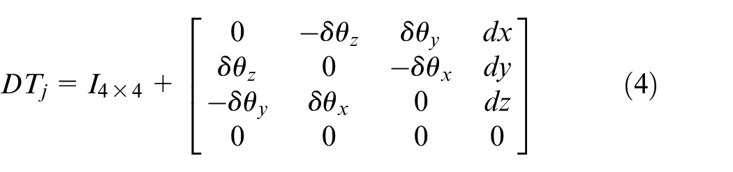
where
Where
To calculate the measure
Optimisation set up
The problem described in section 2 can now be formulated as an optimisation problem. The design variable vector consists of the various components of the DHTM participating in the assembly models and are denoted as X. The optimum pre-bored hole diameter can be calculated as a by-product of the solution of the following optimisation problem:
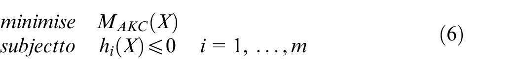
where
Case study
The case study concerns the joined wing configuration of the RACER compound rotorcraft, depicted in Figure 1 and is reproduced in Figure 6. Applying the dimensional management methodology described in section 3, the first step is to assign appropriate frames to the various interfaces of the joined wing structure as shown in Figure 6. All of the frames are expressed with respect to the aircraft global coordinate system.
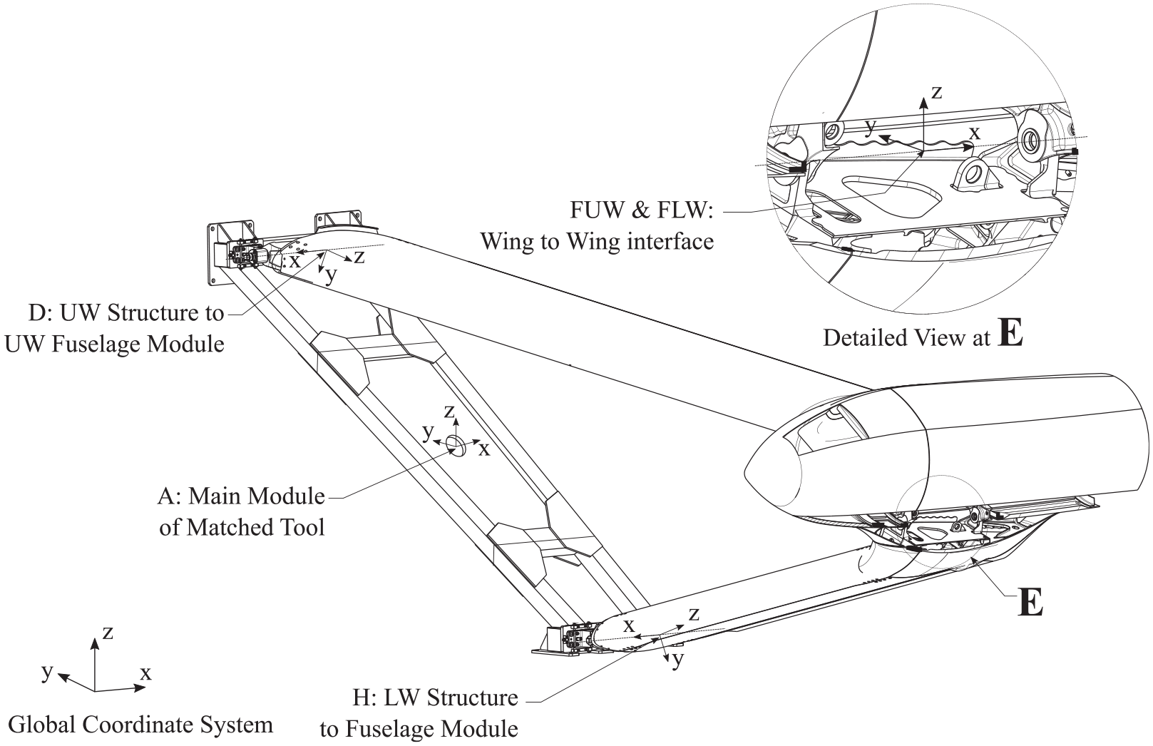
Datum reference frames used within the analysis for the matched tooling, UW and LW structure. 24
The coordinate system for the main body of the matched tooling is at location A. Frames were assigned to the interfaces between the matched tooling and the UW and LW subassemblies at locations D and H respectively. It should be noted that the interfaces D and H correspond to wing to fuselage hinge joints and thus the UW and LW subassemblies are free to rotate with respect to the x axis of the respective frames. Those joints give the opportunity to wash-out part of the variation in the z-direction with respect to the global coordinate system, reducing the tolerance stack-up at the wing-to-wing interface. This is taken into account in the analysis of this case study by nesting an additional optimisation problem inside the main optimisation problem. Furthermore, two separate frames are established at the wing-to-wing interface at point F. That is, the frames FUW and FLW for the UW and LW subassemblies respectively. In the nominal form of the joined wing, those two frames coincide as depicted in the detail of Figure 6.
Additional frames need to be established in order to model and quantify the AKC as depicted in Figure 7. Frames are established at the nominal centre of the hinge bore on surfaces 1, 3 and 4, identified in Figure 7, for the nominal form of the assembly. A frame is also defined at the centroid of the surface 4, at point 4o, in order to take into account geometrical tolerances related to surface 4. Finally, from the interchangeability (ICY) drawings, 31 the position of the parent component of the female lug is dependent on another additional datum feature. The positional variation of this feature affects the wing-to-wing connection and thus, the specified AKC. A frame on the datum feature, identified by point K is depicted in Figure 7, is included to account for this variation.
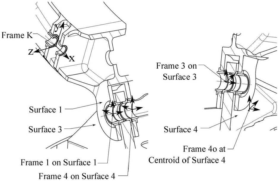
Identifying datum reference frames 1, 3, 4, 4o and K. 24
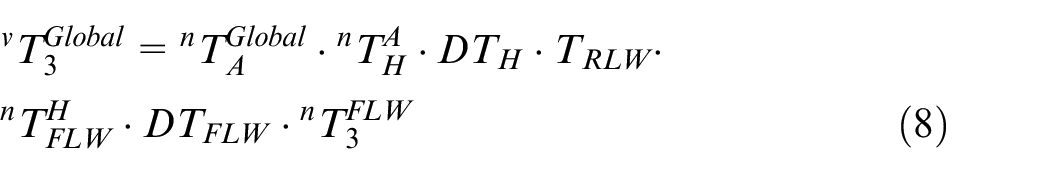
From geometrical consideration of the varied form of the assembly, the specified measure,
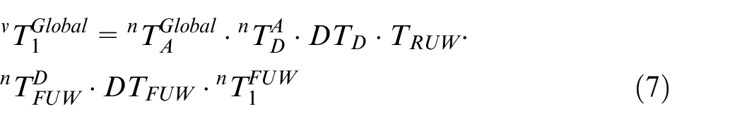
and
and
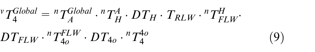
All the HTMs on the right hand side of the equations (7)–(9) can be rewritten using
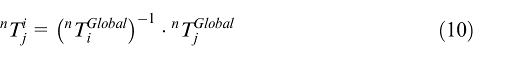
where {i,j} corresponds to {A,D}, {D,FUW}, {FUW,1}, {A,H}, {H,FLW}, {FLW,3}, {FLW,4o} and {4o,4}. Therefore HTM
The variation related to the interfaces of the wing and captured in the ICY drawing was introduced in the assembly models of equations (7)–(9) by considering appropriate DHTMs. Therefore,
Sources of variation related to the interfaces of the matched tooling and the UW and LW subassemblies.
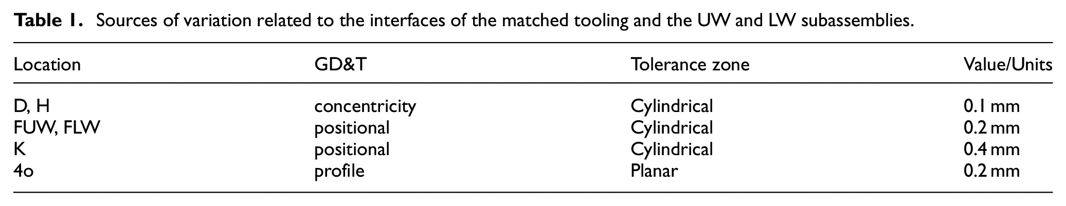
Finally,
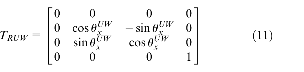
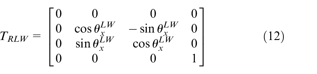
where
Results and discussion
The optimisation procedures detailed in section 4 were applied to calculate the measure
Hinge bore diameter in mm for the modular and one-piece matched tooling.
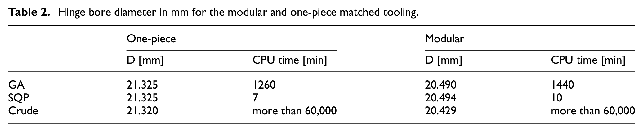
For reference, the nominal hinge bore diameter is D = 21.876 mm. Implementing the suggested dimensional management methodology, the worst-case scenario results in a pre-bored hole diameter 0.556 mm smaller than the nominal diameter (crude approach). This means that, in order to account for the variation in the various interfaces of the wing assembly indicated in ICY drawings, the pre-bored hole diameter should be drilled equal to 21.320 mm (crude approach). The comparatively large size of the optimum, undersize hole diameter indicates that (a) the manufacturing and assembly tolerances throughout the structure are well controlled such that the potential variation at the hinge joint is limited; and (b), that the assembly process can be accelerated whilst avoiding all the drawbacks listed in section 1.
Comparing the optimisation algorithms with the crude simulation approach, both algorithms were able to find similar results. Results in Table 2 illustrate agreement at least at the first decimal place of the calculated diameter values. Both GA and SQP were able to find a value equal to 21.325 mm, very close to the benchmark approach. However, for SQP, the whole process was iterated a few times in order to have an indication about the robustness of the identified minimum. After some experimentation, the best output was achieved by setting the initial design point equal to zero whilst the convergence of the algorithm is presented in Figure 8. Regarding the GA algorithm, the population size was set equal to 250 and a limit up to 1000 generation was applied. The algorithm chooses parents for the next generation in proportion to the fitness scores (objective function value) of the individuals in the current population; whilst children are generated based on elite, mutation and crossover selection. The convergence of the GA algorithm is presented in Figure 8. Considering the CPU time of running those algorithms, it is obvious that the SQP algorithm gives the fastest calculations, finding the minimum in only 7 min whilst the crude simulation approach needed more than 1 month to search the design variable space and identify the result. However, Table 2 illustrates that unless a strategy is devised and implemented to deal with the convergence of the SQP method to a global minimum, then the use of GA is a good compromise between the speed of the calculations and the ability to find values close to the minimum.
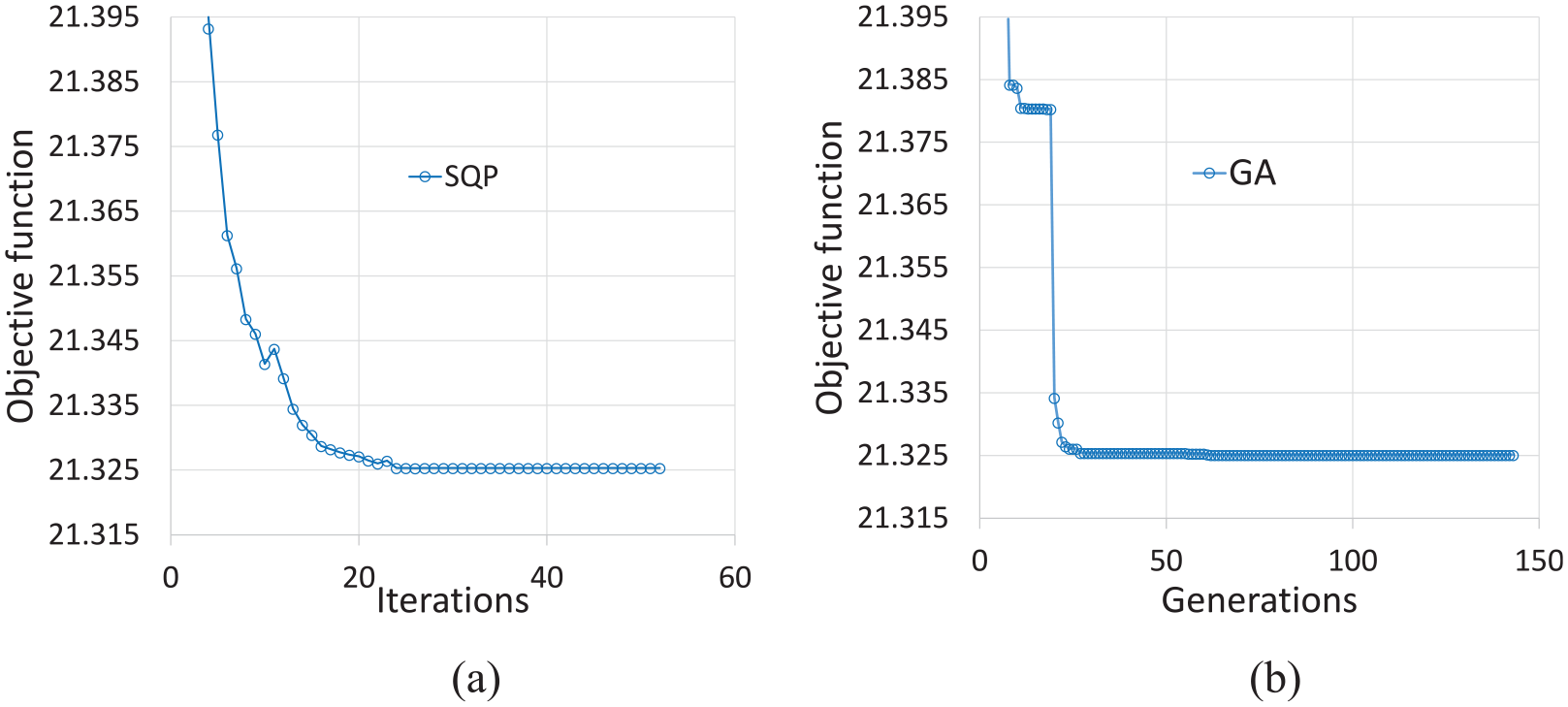
Convergence of the: (a) SQP and (b) GA algorithm for the ‘One piece’ case study.
An interesting occasion was encountered during the preliminary design stage of the joined wing configuration in which it was debated whether the matched tooling configuration could be designed either as a one-piece tool, that is, the case study presented in section 4, or as a modular version made from three different pieces. For the latter case, the obvious benefit to this opportunity is that the individual wing structures would be independently assembled using an exact replica of the fuselage hinge hardware.
The suggested methodology described in section 3 was implemented once more by taking into account the additional sources of variation introduced by the new interfaces created when splitting the matched tool in to three, modular pieces. Results are presented in Table 2 under the heading ‘Modular’. The pre-bored hole diameter was calculated equal to 20.429 mm (crude approach). This reduce the pre-bored hole diameter by 1.447 mm compared to the nominal size of the bore. The comparison between the results in Table 2 for the modular and the one-piece matched tooling indicates a difference in the pre-bored hole diameter of approximately 1 mm. The difference in diameter is considered to be small when reviewed in terms of drilling process time and therefore, the modular matched tooling could potentially be used to assemble the joined wing, despite the additional variation that is inserted into the tolerance chain.
Conclusion
A dimensional management procedure was developed to deal with projected errors and successfully join two subassemblies in a common hinge line interface. The optimum pre-bored hole diameter was specified by establishing an appropriate measure that considers the assembly process and permits the application of optimisation algorithms. Therefore, the robust optimisation problem of finding the Chebyshev centre, in the presence of variation, is transformed under valid engineering judgment into a typical optimisation problem for which the worst-case scenario can be identified.
The methodology was demonstrated for the joined wing configuration of AIRBUS Helicopters’ RACER compound rotorcraft. The study revealed that the bores at the hinge line interface of the two wing subassemblies can be pre-opened at the machining stage of the interfacing parts by approximately 0.6 mm smaller than their final nominal size, in order to accommodate variation due to manufacturing and assembly uncertainties. Therefore, a much better starting point is identified for the final drilling of the hinge line interface whilst a considerable reduction drilling process duration at the final assembly stage is expected.
Finally, the methodology was successfully applied to confirm the decision on the tooling configuration as presented in section 5. The additional uncertainty introduced by splitting the matched tooling into a modular tool only reduced the optimum pre-bored hole size by 1mm compared to the one-piece configuration and therefore the best option can be selected based on more quantitative evidence rather just on engineering judgement.
Footnotes
Declaration of conflicting interests
The author(s) declared no potential conflicts of interest with respect to the research, authorship, and/or publication of this article.
Funding
The author(s) disclosed receipt of the following financial support for the research, authorship, and/or publication of this article: This project has received funding from the Clean Sky 2 Joint Undertaking (JU) under grant agreement number CSJU-CS2-GAM-AIR-2014-2015. The JU receives support from the European Union’s Horizon 2020 research and innovation programme and the Clean Sky 2 JU members other than the Union.