
Abstract
In manufacturing engineering, locating error analysis for workpieces is a common issue in predicting the quality of machined features, computer-aided fixture design and tolerance allocation. This article presents a locating error analysis approach for workpiece with general fixture layouts and parameterized tolerances. Initially, a fixture is transformed into six locating points in the space. A linearized model is then derived to convey the relationship between the errors of locating points and the locating errors, by using the implicit differentiation and the first-order Taylor expansion. Then, the tolerances for the features of plane, cylinder and free-form surface are parameterized using 4 × 4 homogeneous transformation matrices. Finally, two formulas are derived to calculate the errors in the locating points in surface-to-surface mating and hole-to-pin mating. Two workpieces are presented to demonstrate and validate the proposed method. The relative errors between the results calculated by the proposed method and the results calculated by 3DCS are less than 3%.
Keywords
Introduction
In manufacturing engineering, designers need to accomplish two basic tasks: machining surface accuracy check and locator tolerance allocation. 1 In recent years, aided by developments in computer-aided technology, these two tasks are performed more simply and efficiently. 2 With computer-aided design (CAD)/computer-aided manufacturing (CAM) platforms, information such as geometrical features and tolerances is easily gathered, allowing a three-dimensional (3D) fixture layout for a workpiece to be designed rather quickly. Despite this, designers still encounter significant; for example, knowing how to best use the 3D information efficiently to predict the quality of a workpiece, and to verify the reasonability of a tolerance assignment. To remedy this, a mathematical model related to tolerances, geometrical errors and the quality of workpieces is necessary. The interactions between workpieces and fixtures in the manufacturing processes are quite complex, and two important factors, datum errors and fixture errors, affect the quality of machined features. In this article, we primarily consider these two factors to present a method for locating error analysis of a workpiece, which must be completed before performing the two main tasks aforementioned.
Previous research on locating error analysis for workpieces has focused chiefly on fixture layout optimization. According to the configuration of the fixture, these methods can be divided into two categories: “3-2-1”-oriented and “general fixture layout”-oriented. In the “3-2-1”-oriented methods, Cai et al. 3 established a mathematical model to express the relationship between the errors of locating pin and the locating errors of workpiece. Zhang et al. 4 proposed an approach for setup planning with a combination of process planning and computer-aided fixture design. In this article, the workpiece locating errors and the machining errors were used as evaluation indexes for fixture design. With consideration of 3-2-1, Pin-Hole and V block, Rong et al. 5 proposed a locating error analysis method for three fixture layouts. In Raghu and Melkote, 6 Qin et al., 7 Vishnupriyan et al., 8 Zhu et al. 9 and Wang, 10 factors including geometric errors of workpiece and fixture are considered. In Raghu and Melkote 6 three major error sources, including fixture geometric errors and the elastic deformation of fixture and workpiece due to fixturing forces, were considered. Qin et al. 7 and Vishnupriyan et al. 8 presented a general analysis methodology that is able to characterize the effects of localization error sources based on the position and orientation of the workpiece. Zhu et al. 9 presented a prediction model of workpiece locating error caused by the setup error and geometric inaccuracy of locaters for the fixtures with one locating surface and two locating pins. Wang 10 established a mathematical model to convey the relationship between the geometric errors and locating errors. Tolerance analysis for workpiece and fixture is also considered by researchers. Asante 11 presented a methodology for modeling and analyzing the combined effect of workpiece geometric errors, locator geometric error and clamping error on a machined feature based on small displacement torsors. Loose et al. 12 integrated Geometric Dimensioning & Tolerancing (GD&T) factors into locating error analysis. Choudhuri and De Meter 13 analyzed the tolerances of profile and angle for the machined features with consideration of datum errors, geometric errors. More recently, Zhou et al. 14 presented a state-space model and its modeling strategies to describe the variation stack-up in multi-operational machining process. In the method, surface deviation was expressed in terms of deviation from nominal orientation, location and dimensions, and a part’s deviation was expressed in terms of the deviation of its surfaces and is stored in a state vector x(k). In “general fixture layout”-oriented methods, Carlson 15 presented a quadratic sensitivity analysis for locating errors with the consideration of locator errors and the geometric errors of workpiece. Wang 16 presented an analysis method to describe the impact of locating error sources on the geometric errors of machined features. The method has shown the importance to consider the errors in the multiple critical locating points (LPs) of fixture. Loose et al. 17 developed a linear model to describe the dimensional variation propagation of machining processes with general fixture layouts. However, in the method, the locator was treated as a point, so it could not deal with plane/plane contact or cylinder/cylinder floating contact when positioning the workpiece.
As established by previous researchers, it is clear that locating error analysis for a workpiece plays an important role in fixture layout optimization and tolerance allocation. However, the types of methods presented in much of this literature have shortcomings. First, the methods for locating error analysis are chiefly for 3-2-1 fixture layout, which limits the application of those methods. Also, the key pieces of information in the process of workpiece locating, geometric features and tolerances, are not integrated into the current popular methods. This creates difficulties in applying said methods to the tolerance allocation of workpieces and fixtures, or to integrate the methods into current CAD/CAM platforms. This article is organized as follows. In section “Linear locating error analysis model for workpiece,” a linear deviation model for workpiece locating is derived. In section “Tolerance modeling based on variational feature,” a parameterized tolerance model is presented for planar, cylindrical, free-form surface features. Two formulas are derived to calculate the errors of LPs in surface-to-surface mating and hole-to-pin mating based on the parameterized tolerance in section “Calculating the deviations of LP.” Two workpieces are illustrated to validate the proposed method in section “Numerical experiments.” Finally, some conclusions of this article are presented in section “Conclusion.”
Linear locating error analysis model for workpiece
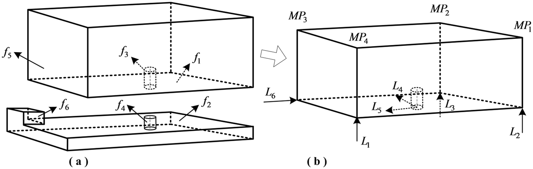
In a typical process of workpiece–fixture assembly, a workpiece is constrained by a fixture. The constraints between the workpiece and fixture are characterized by two features, which are carriers of datum errors and fixture errors. As illustrated in Figure 1, the block is constrained by four geometrical constraints (or matings): the pair f1 and f4 is a plane-to-plane constraint; the pair f1 and f4, the pair f2 and f5, the pair f2 and f6 and the pair f3 and f7 are plane-to-point constraints. It is noted that f5, f6 and f6 are small planes, so they are considered as points. According to the theory of virtual LPs proposed by Huang et al.,18,19 a geometrical constraint can be transformed into several LPs according to certain principles. In this article, the following set of principles are adopted: first, three LPs are selected on the primary datum surface, which make the area as large as possible; second, two LPs are selected on the secondary datum surface, which make the distance as long as possible; third, an LP is selected in the center of the tertiary datum surface. By these standards, we can obtain a set of LPs interactively on the CAD model. As shown in Figure 1(b), f1 is the primary datum, allowing the designers to select three LPs (i.e. LP1, LP2 and LP3) from the workpiece’s CAD model and creating a large area with the three LPs; similarly, f2 is the secondary datum, so two LPs (i.e. LP4 and LP5) are selected from the CAD model, and creating a lengthy distance; finally, an LP (i.e. LP6) is selected on feature f3. It is noted that the constraint is constructed by a pair of features, so when selecting LP1–LP6 on the workpiece, it is necessary to ensure corresponding points on the fixture, as with LP1′–LP6′ in Figure 1(c). In other words, the LPs are selected as a pairing: one is on the workpiece and another is on the fixture. The coordinates of the two points are identical.
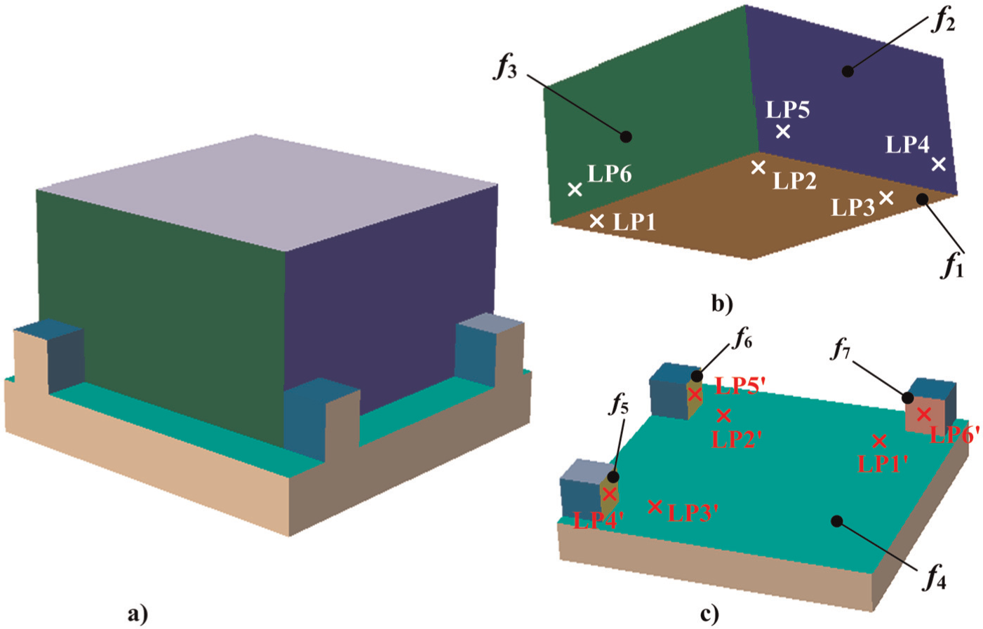
A block’s LPs: (a) a block’s locating and (b) fixture.
In this article, to derive a general model for locating error analysis, a fixture is turned into six LPs, which make up a general fixture layout. As shown in Figure 2, the black line indicates the theoretical position of the workpiece and the blue line indicates the real position of the workpiece. L1–L6 are the six LPs.
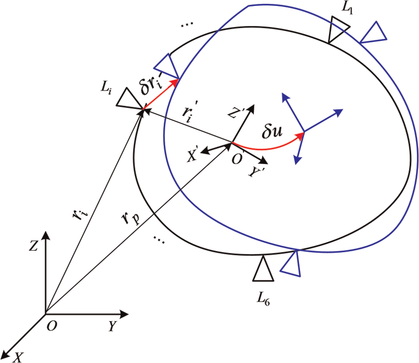
General fixture layout of a 3D part.
It is assumed that

In which,

where
Combine all

By defining

Let

If the workpiece is in a deterministic position, then

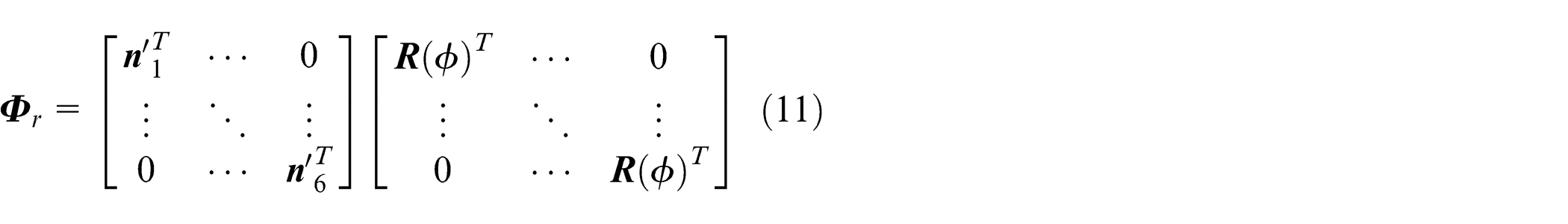
In which
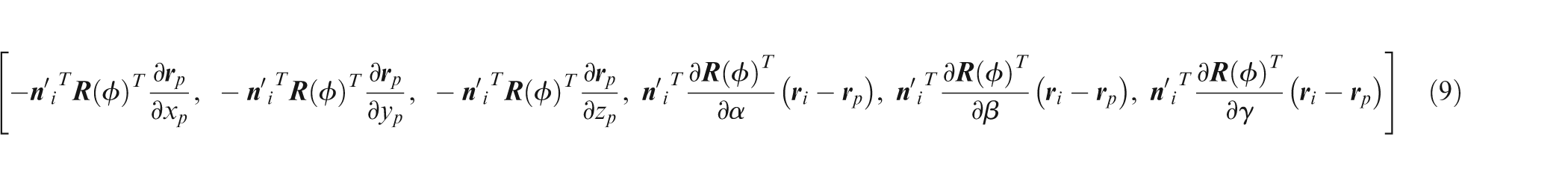
The expressions of
Derivation of the Jacobian (
It can be known from formulas (4) and (7) that
Without loss of generality, assume

Derivation of
According to formulas (2) and (4),
When
Tolerance modeling based on variational feature
Representation for feature and its deviations
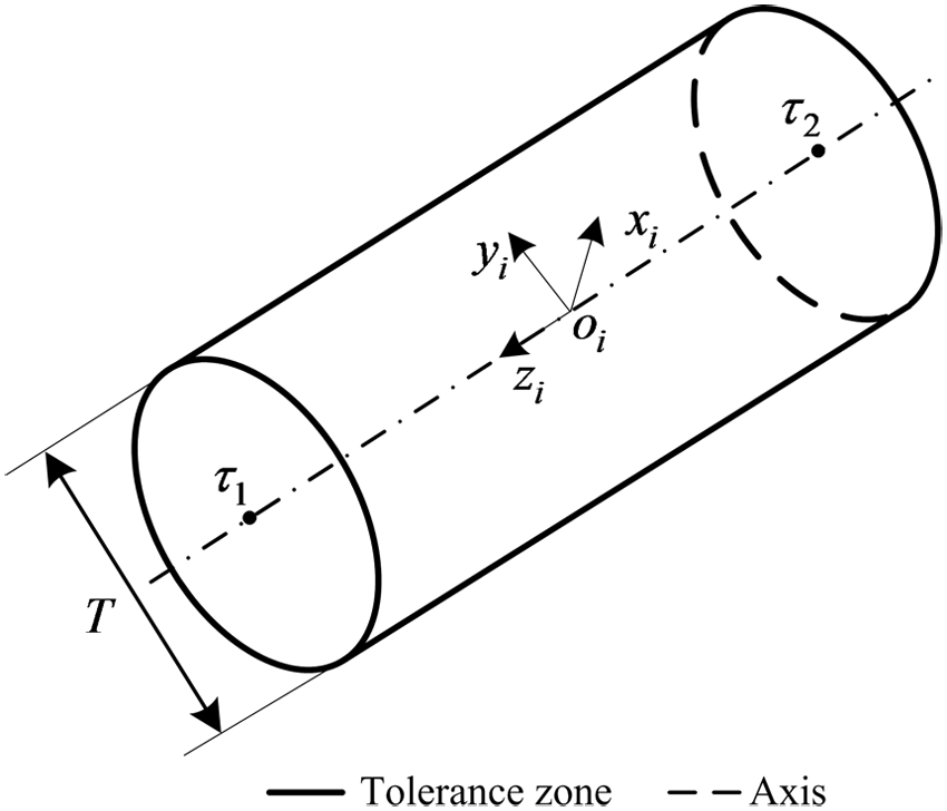
In order to self-location, the workpiece establishes several matings with the fixture, such as surface-to-surface mating, hole-to-pin mating and others. These matings are composed of features, and deviations in these features are what cause locating errors. Deviations in the features used to generate matings are determined by tolerances. In this article, it is assumed that information, such as features (points, planes and surfaces) and tolerances, are captured by the CAD system. As shown in Figure 3, the cylinder with dashed line represents a nominal feature, and the cylinder with solid line represents a feature with deviations.

where
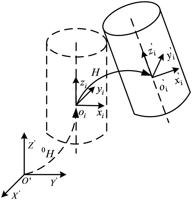
Feature and its deviations.
According to formula (12), the deviations of a feature can be defined as follows

where
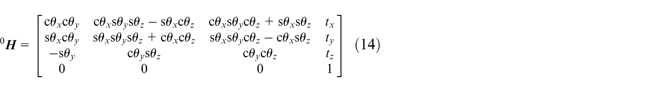
Both the freedom degrees of a feature and their deviations can be expressed by a 4 × 4 homogeneous transformation matrix (HTM). As shown in Figure 3,
Planar feature
Figure 4 is a planar tolerance zone and
Step 1. When the planar feature translates along the xi-axis and yi-axis, or rotates along the zi-axis, no deviations will be produced. The corresponding freedom degrees can be eliminated. Therefore, the deviations of the plane feature can be represented as follows

Step 2. Choose four boundary points of the planar feature as control points, as the
Step 3. Calculate the deviations of the planar feature according to the control points.
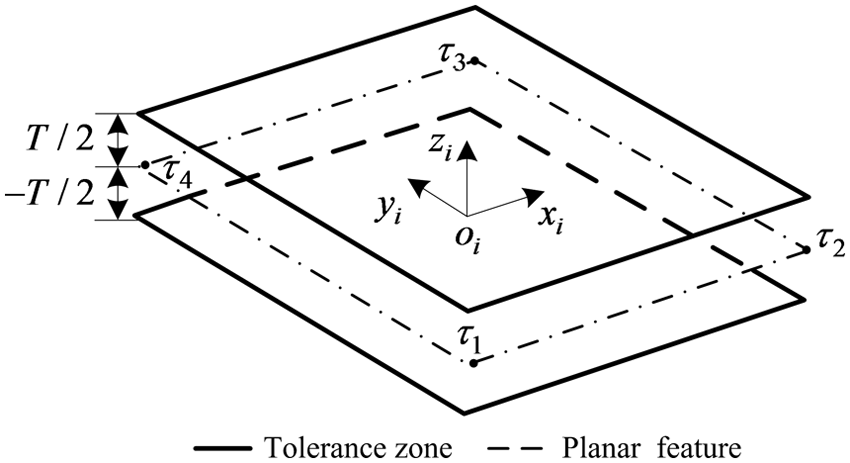
Planar tolerance zone.
According to formulas (15) and (16), the normal deviation of
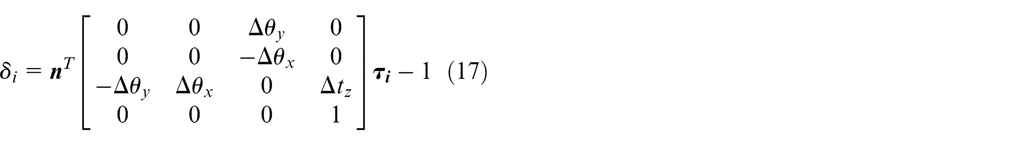
Assuming
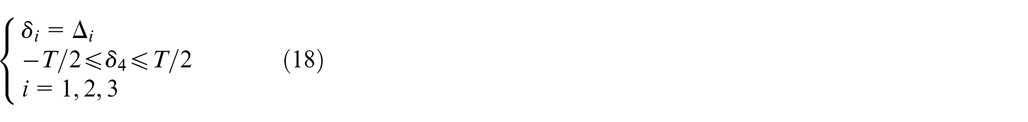
If there is no solution to formula (18), then the three random numbers must continue to be generated until a solution becomes possible.
Cylindrical feature
As shown in Figure 5, an FCS,
Step 1. When the cylindrical feature translates along the zi-axis, or rotates around the zi-axis, no deviations will be produced. The corresponding freedom degrees can be eliminated. Therefore, the deviations of the cylindrical feature can be represented as follows

Step 2. Choose two boundary points (
Step 3. Calculate the deviations of the cylindrical feature according to the control points.
Cylindrical tolerance zone.
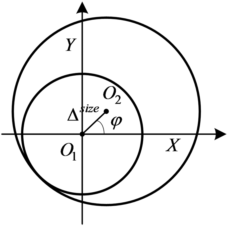
As shown in Figure 6,
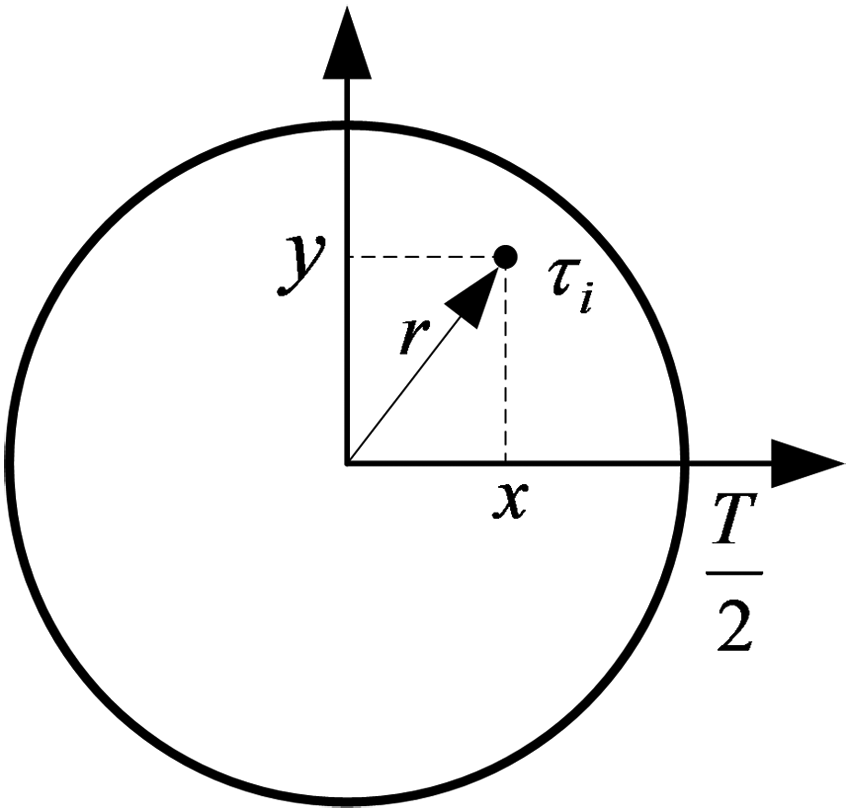
Circular tolerance zone of
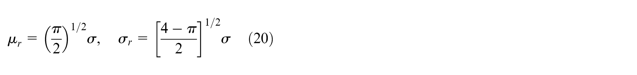
According to the principle of 6-sigma, the expansion of

Thus, it is known that
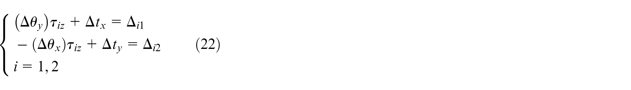
If there is no solution to formula (22), then the four random numbers need to be generated again until a solution is found.
Free-form surface feature
Figure 7 is the tolerance zone of a free-form surface.
Step 1. The free-form surface can be represented by three translational and three rotational degrees of freedom. Therefore, the deviations of the free-form surface can be represented as

Step 2. Transform the free-form surface into a series of control points, illustrated as
Step 3. Calculate the deviations of the free-form feature according to the control points.
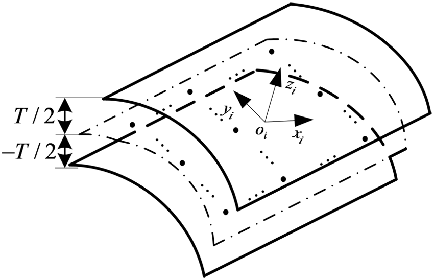
Tolerance zone of free-form surface.
Let
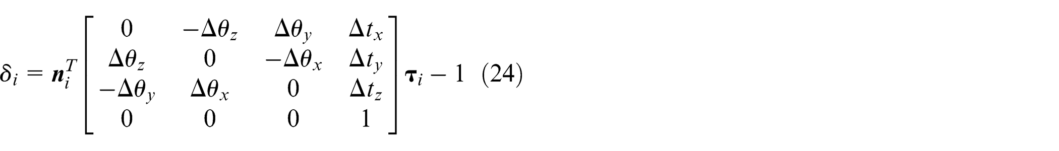
Suppose the normal deviation (
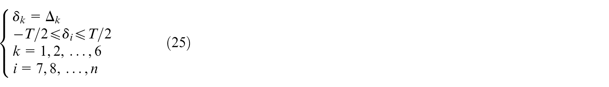
If there is no solution to formula (25), then the six random numbers need to be re-generated until a solution is possible.
Calculating the deviations of LP
According to the principle of virtual LP,18,19 the features to generate mating can be simplified as several LPs. The deviations of these LPs will be derived based on the deviations of the features. In this article, features on workpiece and features on fixture are defined as object features (OFs) and target features (TFs), respectively. Workpiece locating is the process which establishes matings between OFs and TFs.
Surface-to-surface mating
A surface-to-surface mating is illustrated as Figure 8. In Figure 8,
Theoretical situation. There are no deviations between the OF and TF in this situation, and
Real situation. There exist deviations between the OF and TF, and these two features contact at the point

where
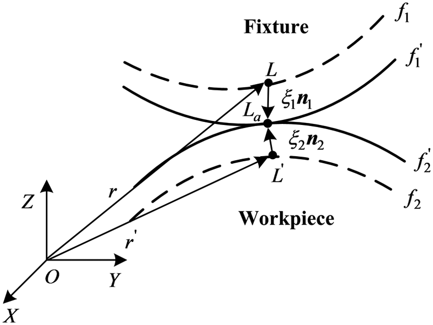
Deviation of LP in surface-to-surface mating.
Hole-to-pin mating
Hole-to-pin mating is a widely applied process in workpiece locating. The deviations of an LP in hole-to-pin mating concern the dimensional deviations and positional deviations of the hole and pin. The pin and hole are considered the OF and TF, respectively. To simplify our analysis process, we assume the axes of the hole and the pin are parallel to the z-axis. The procedure to calculate the deviations of an LP in hole-to-pin mating is as follows:
Calculate the deviations of the LP caused by the positional deviations of the hole and the pin.
Let

where
Calculate the deviations of the LP caused by the dimensional deviations of the hole and pin.
As illustrated in Figure 9, it is assumed that the hole and the pin are always in contact during workpiece locating, so the deviations of the LP caused by dimensional deviations of the hole and pin can be represented as follows

where
Gap of hole-to-pin mating.
Calculate the integrated deviations of the LP in hole-to-pin mating.
The integrated deviations of the LP in hole-to-pin mating are influenced by positional and dimensional deviations. By combining formulas (27) and (28), the integrated deviations of the LP in hole-to-pin mating can be derived

Numerical experiments
Case 1: a block
As shown in Figure 10(a), the 200 mm × 200 mm × 100 mm block is located by a fixture. There are six features used to construct matings here. First,
A block’s locating: (a) a block and its fixture and (b) general fixture layout of the block.
Parameterized tolerances
In this case, we chose the feature f1 as an example of parameterized tolerance. As illustrated in Figure 11, there are four control points on f1 presented as
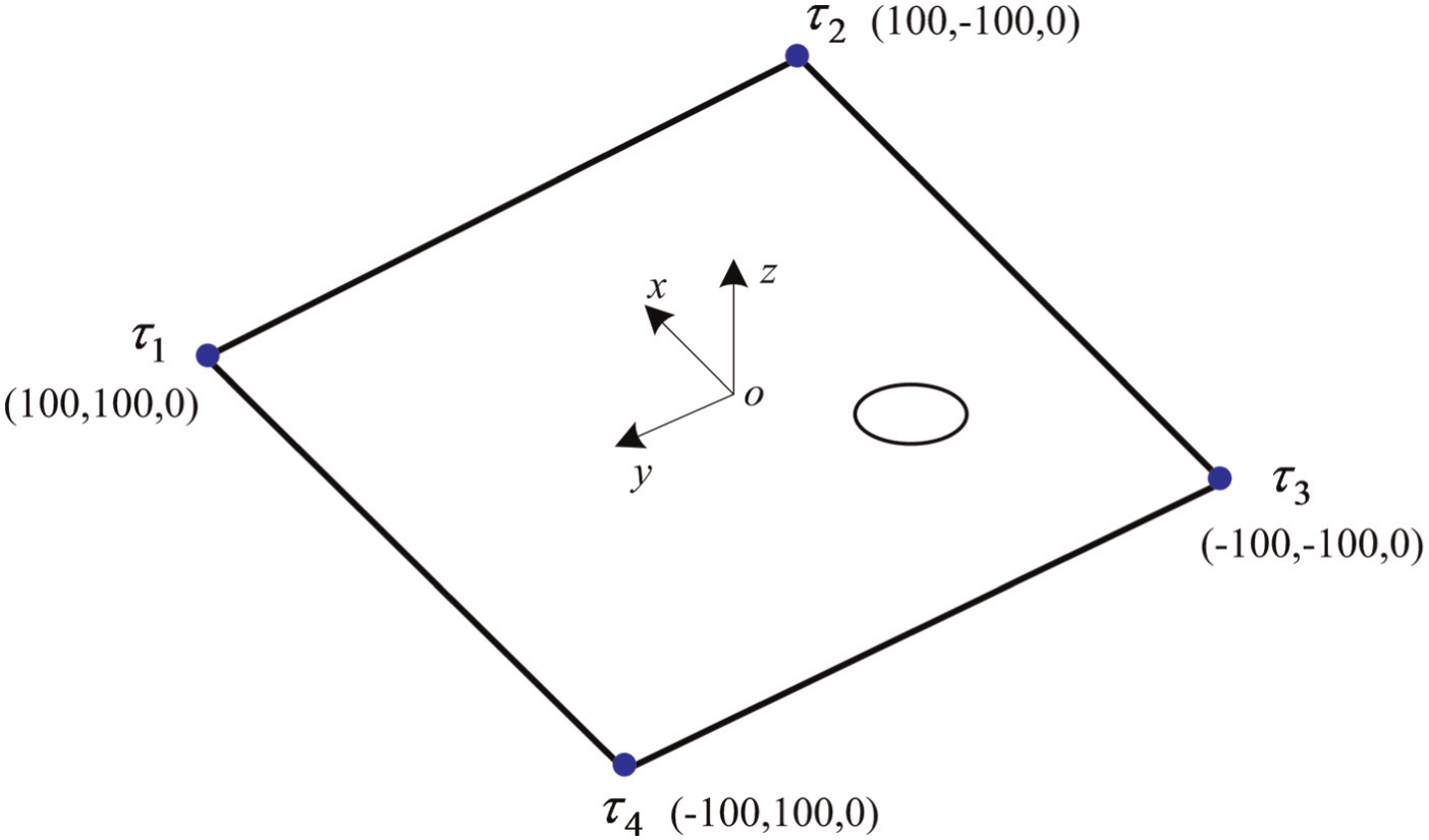
Feature f1 and its control points.
According to formula (16), the deviations of f1 are presented by three parameters (
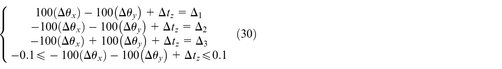
According to formula (30),
Locating error analysis
In Figure 10(b), the mating formed by
LPs of the block.
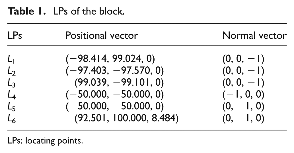
LPs: locating points.
As illustrated in Figure 10(b), the four top points, MP1–MP4, are selected as measuring points (MPs). Similar to section “Parameterized tolerances” and to the linearized locating error analysis model in section “Linear locating error analysis model for workpiece,” the normal deviations of MP1–MP4 are analyzed. The positional vector and normal vector of the MPs are presented in Table 2.
Measuring points of the block.
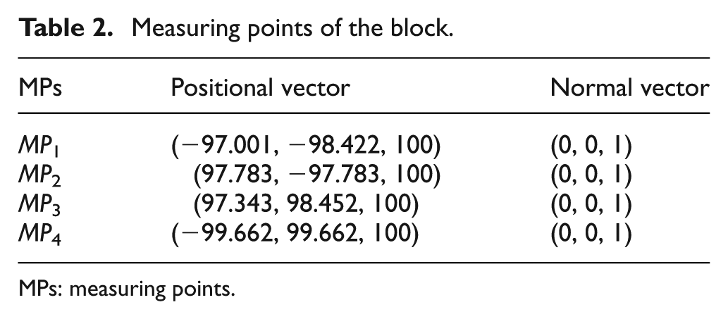
MPs: measuring points.
The results are calculated by the proposed method and 3DCS software, a standard industrial software used for tolerance analysis, as shown in Table 3. It can be seen that relative errors between the results are small, in which the differences (relative errors) between the proposed method and 3DCS are <1%.
The results calculated by the proposed method and 3DCS software.
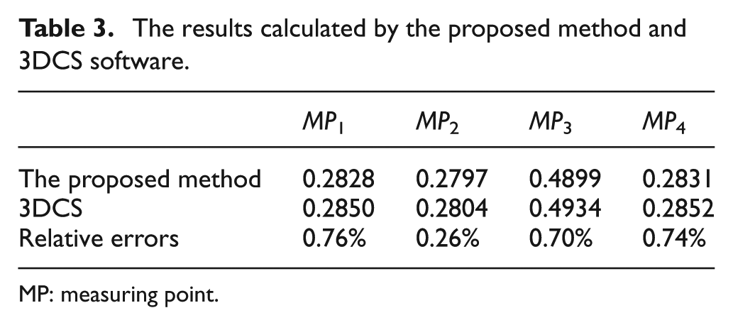
MP: measuring point.
Case 2: a rib
The location of a rib during machining can be simplified, as shown in Figure 10. L1–L6 are the LPs:
LPs of the rib.
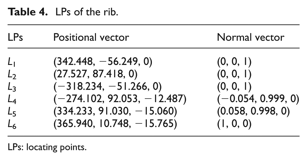
LPs: locating points.
Six MPs are selected for the rib, represented as MP1–MP6 in Figure 12. The positional vector and normal vector of these MPs are shown in Table 5.
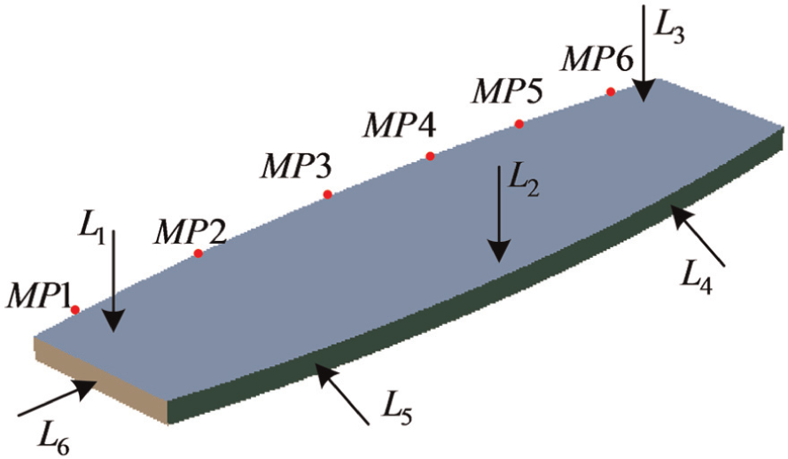
General fixture layout of a rib.
Measuring points of the rib.
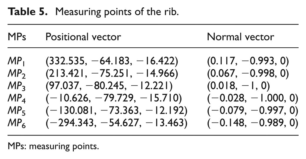
MPs: measuring points.
Parameterized tolerances
For this demonstration, we chose the secondary datum as the example of parameterized tolerance, which is a free-form surface feature. It is assumed that the workpiece is designed by CATIA, which is a widely used CAD software in the industry currently. We use the tool “CAA for CATIA” to create a program when capturing control points on a surface. As illustrated in Figure 13, 100 points are retrieved for the secondary datum. The information for the LPs is presented in Table 6.
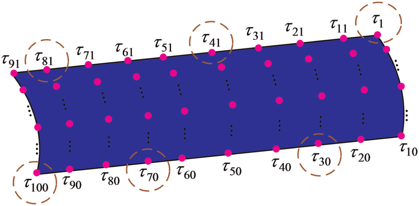
The secondary datum and its control points.
Control points of the secondary datum.
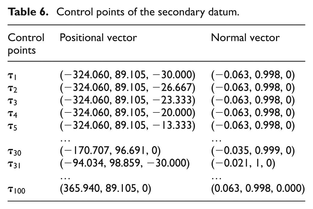
As explained in section “Free-form surface feature,” to calculate the six parameters (
For free-form features, it may be very time-consuming to acquire control points by processing such complicated surfaces. Here, a number of experiments, capturing control points for the secondary datum, are performed and analyzed. As shown in Figure 14, as the number of control points increases, so does the computing time. When the number of control points is
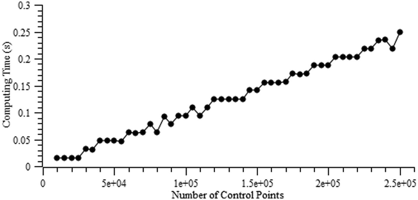
Computing time of capturing control points in the secondary datum.
Locating error analysis
The normal deviations of MP1–MP6 are calculated. The results are compared to the results calculated by 3DCS software, as shown in Table 7. The maximum relative error between the results is 2.4%, confirming the efficacy of the proposed method.
The results calculated by the proposed method and 3DCS software.

MP: measuring point.
Conclusion
This article presents a locating error analysis method for workpieces based on parameterized tolerance. In this method, the fixture is turned into six LPs. A linearized model is then derived to express the relationship between the errors of the LPs and the workpiece locating errors. Then, the tolerances for planar, cylindrical and free-form surface features are parameterized using 4 × 4 homogeneous transformation matrices. Finally, two formulas are derived to calculate errors of the LPs in surface-to-surface mating and hole-to-pin mating. The proposed method provides highly accurate calculated results and shows potential to provide a basis for fixture layout optimization and tolerance allocation. However, there still exist some deficiencies in this article. For one thing, only tolerance modeling for planar features, cylindrical features and free-form surface features are considered. Additionally, it is assumed that the LPs contact with the workpiece on a rigid plane. Typical properties of contact surfaces, such as curvature and deformation, are neglected. The method in this article will be improved, as such, during the follow-up research.
Footnotes
Declaration of Conflicting Interests
The author(s) declared no potential conflicts of interest with respect to the research, authorship, and/or publication of this article.
Funding
The author(s) disclosed receipt of the following financial support for the research, authorship, and/or publication of this article: The authors gratefully acknowledge the support of this work by the National Key Technology Research and Development Program of China (2011BAF13B03), the Aerospace Science and Technology Support Fund (2013-HT-XGD) and the Equipment Pre-research Program.