
Abstract
Compared to conventional circular components such as keys, splices and pins, polyhedron components have many advantages as connecting components in torque transmission systems, including a greater shear strength, an improved fatigue strength and an improved transmission efficiency. However, the performance of such components is critically dependent on the precision of the manufacturing process. Accordingly, this study derives a mathematical model based on the homogeneous coordinate transformation method to facilitate the design, machining and error compensation of generic polyhedron components with n sides. The validity of the proposed approach is demonstrated numerically using polyhedron components with three, four and five sides. The results confirm that the proposed machining and error compensation method provides a simple yet versatile approach for fabricating a wide range of polyhedron components.
Introduction
Polyhedron components are used in the transmission systems of many industrial, agricultural and automotive systems. On a traditional lathe, the part rotates but the cutter is fixed, and thus, the locus of the edge must be either a circle or a spiral. Consequently, polyhedron components are generally fabricated using shaping and milling methods. However, both methods require an indexing motion and a discontinuous cutting process. Thus, neither method is suitable for mass production. Consequently, a requirement exists for a systematic modeling approach to facilitate the design, analysis and machining of generic polyhedron components.
Modern computer numerically controlled (CNC) machine tools allow for the drilling, milling and grinding of high-precision components on a single machine with a one-off setup process. 1 As a result, the design and performance evaluation of multi-functional machine tools has attracted significant attention in the literature. 2 Yip-Hoi and Dutta 3 presented a computational technique for determining the maximum turnable state of mill-turn components. Guerra and Hinduja 4 proposed a hybrid method for modeling turned components with non-axisymmetric features using a feature-based library or traditional modeling tools. Lee and Chiou 5 presented a method for calculating the critical separation distance between the part surface and the cutter in mill-turn machines by mapping the part surface and cutter onto an unfolded domain. Thomas et al. 6 used a fast tool servo-mechanism to perform the diamond turning of components with non-rotationally symmetric surfaces.
Rotary machining has attracted extensive attention in the literature. For instance, Nakajima et al. 7 presented a method for evaluating the effect of the tool posture on the rotary cutting process. Ya et al. 8 proposed a method for estimating the material removal rate (MRR) in CNC-controlled rotary ultrasonic machining. Albertelli et al. 9 used an active spindle with piezoelectric actuators to improve the performance and productivity of a small-scale wood rotary planning system. Nakajima et al. 10 proposed a new machining method for difficult-to-machine materials using a multi-tasking lathe.
However, the literature lacks a systematic model for fabricating polyhedron components on a rotary cutting machine tool. Accordingly, this study proposes a simple yet comprehensive method for the design, machining and error compensation of generic polyhedron components with n sides.
The remainder of this article is organized as follows: section “Kinematic modeling of rotary cutting of polyhedron parts” presents the kinematic model for the rotary machining of polyhedron components for the case where the tool and workpiece rotate at constant angular velocities. Section “Numerical simulation” evaluates the practical feasibility of the proposed model by means of numerical simulations. Section “Profile error analysis and compensation” presents a method for dynamically adjusting the distance between the tool carriage and the workpiece so as to improve the precision of the machined polyhedron profile. The validity of the proposed approach is demonstrated numerically using polyhedron components with three, four and five sides. Finally, Section “Conclusion” provides some brief concluding remarks.
In the homogeneous coordinate transformation notation adopted in this study, the point vector axi + ayj + azk is written in the form of the column matrix
Kinematic modeling of rotary cutting of polyhedron parts
This section presents a kinematic model for the rotary machining of generic polyhedron components. In deriving the model, it is assumed that both the tool and the workpiece rotate and the axis of the tool carriage is parallel to that of the part. In modeling the machining process, it is first necessary to number the links of the rotary cutting system sequentially, beginning with the world coordinate frame (labeled as “0” in Figure 1) and ending with the workpiece (labeled as “2”). Note that in Figure 1, R denotes the radius of the blank, h is the desired side length of the polyhedron component, r is the gyration radius of the tool tip and
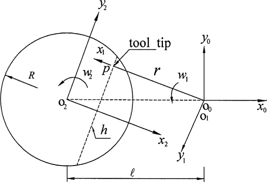
Kinematic model of polyhedron rotary cutting process.
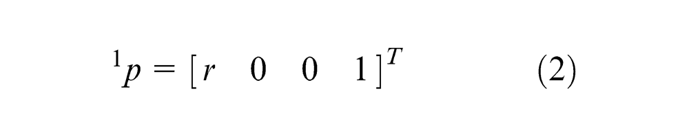
For a polyhedron profile, the cross-sections are identical. Hence, the profile can be modeled using a planar two-dimensional (2D) space representation. Thus, the position of the tool tip in frame (xyz)1 (denoted as p in Figure 1) can be expressed as
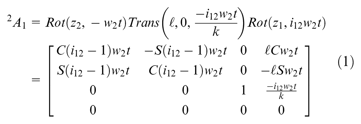
The machined surface of the polyhedron component, 2S, can thus be obtained via coordinate transformation as follows
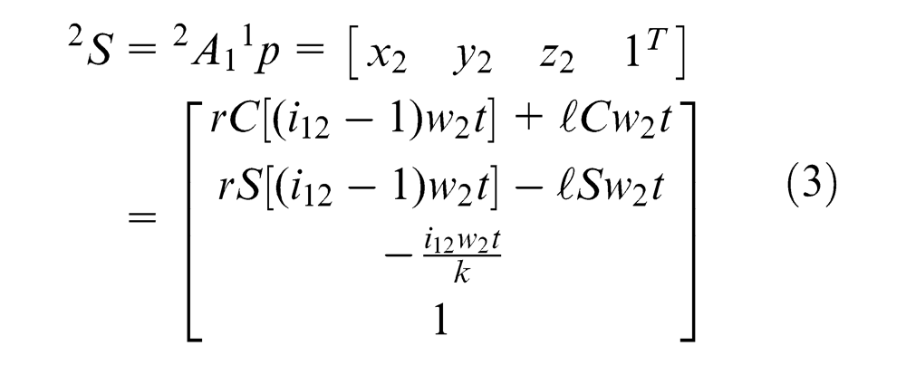
It is observed that the machined profile is determined by two parameters, namely, i12 and
Numerical simulation
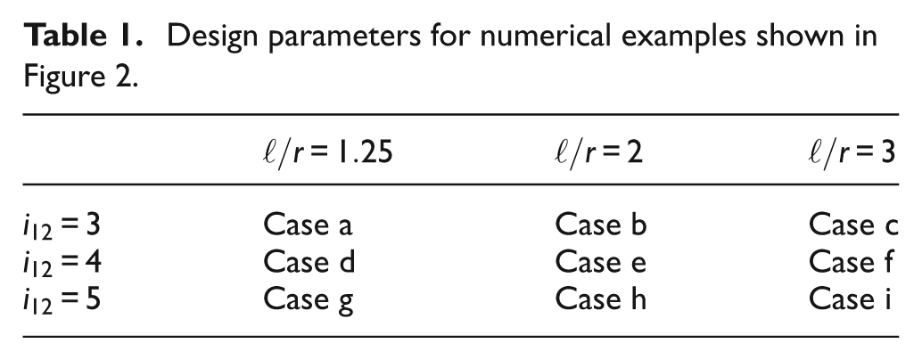
In order to validate the mathematical analyses presented in the previous section, numerical simulations were performed using the parameter settings shown in Table 1. (Note that in the constant angular speed rotary cutting method considered in this study, the feed in the
Design parameters for numerical examples shown in Figure 2.
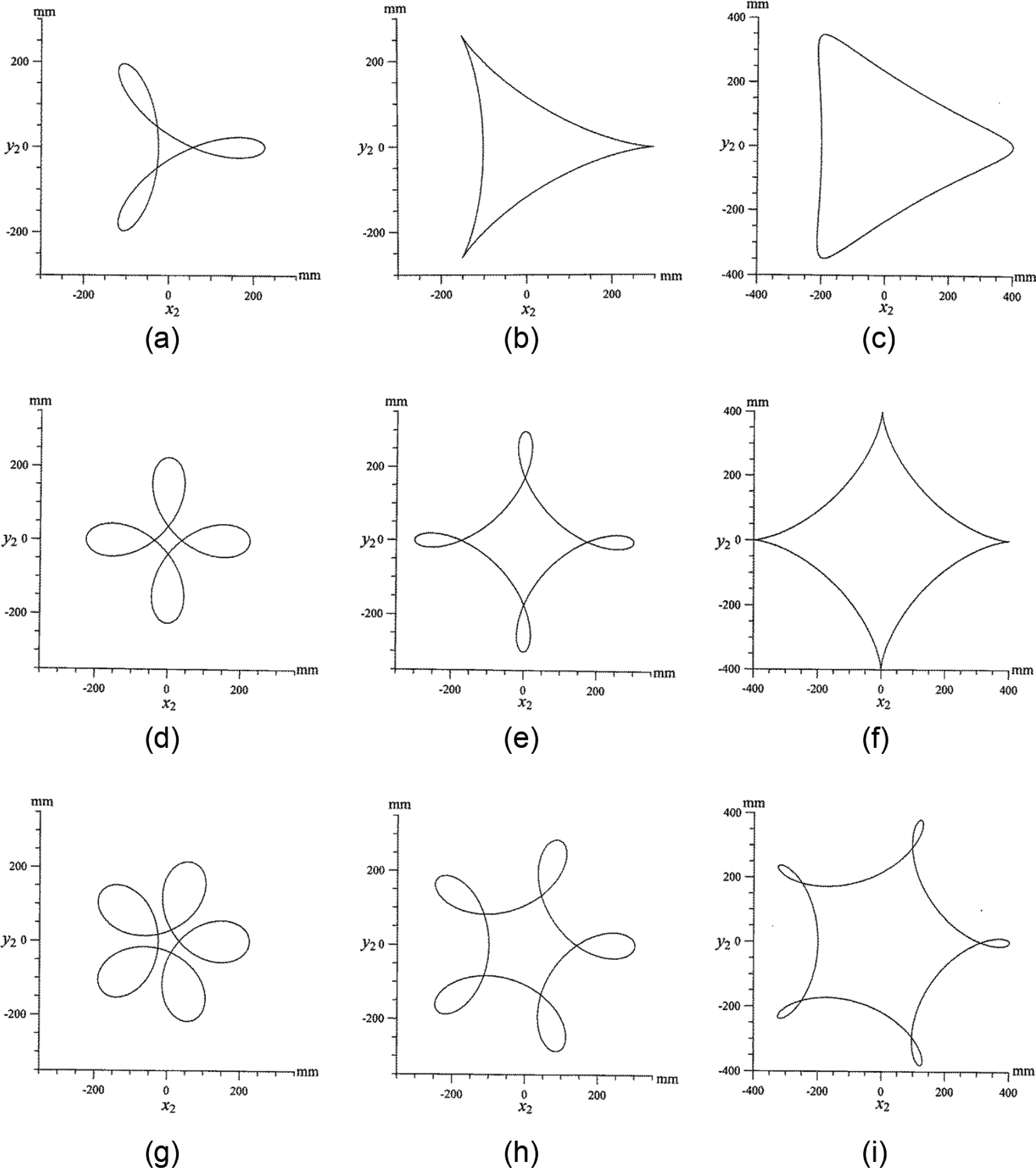
Tool trajectories for nine polyhedron designs specified in Table 1.
Profile error analysis and compensation
The simulation results presented in the previous section show that the center-to-center distance
From Figure 3(a) if the workpiece is stationary, the intersection points A and B of the polyhedron are located on the circumscribed circle and the center-to-center separation distance can be expressed as
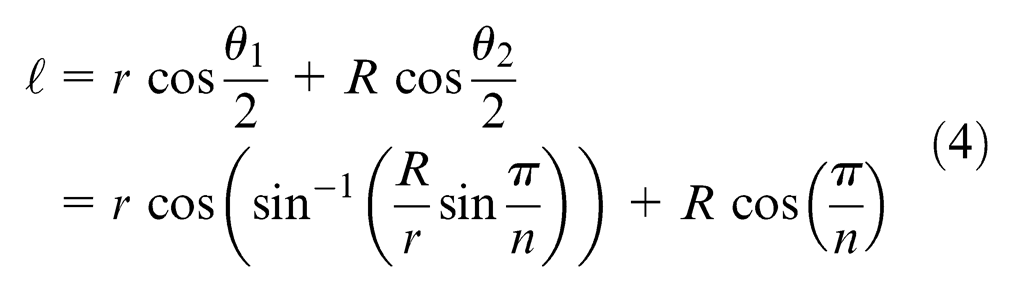
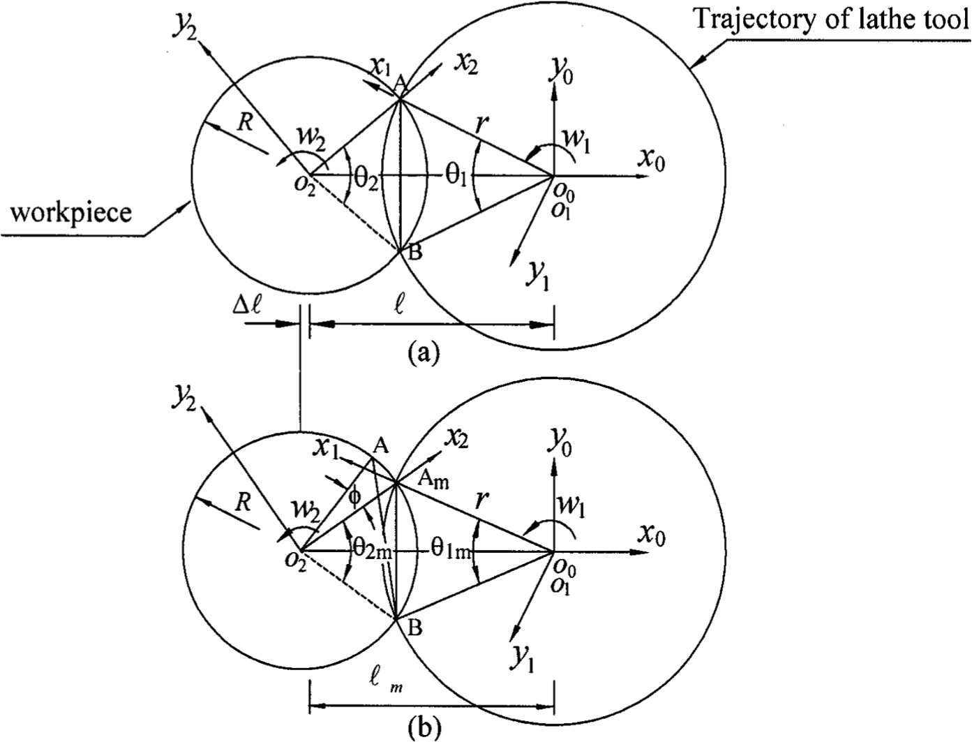
Proposed center-to-center separation distance compensation scheme: (a) stationary workpiece and (b) rotating workpiece.
where n is the number of sides of the polyhedron. However, in a practical machining process, the workpiece rotates, and thus, A and B are located inside the circumscribed circle. The workpiece rotates through an angle φ as the tool cuts along arc AB. Hence, from Figure 3(b), the following relationship is obtained
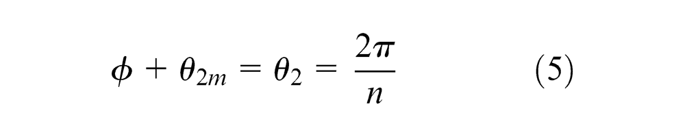
where
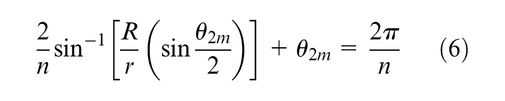
The variable
Let the step size used in the incremental compensation procedure be denoted as
Figure 4 shows that by adjusting the distance between the origins of the workpiece frame and tool frame, the intersection points of the polyhedron remain on the specified circumscribed circle as the machining process proceeds. The circumscribed circle radius error is denoted as
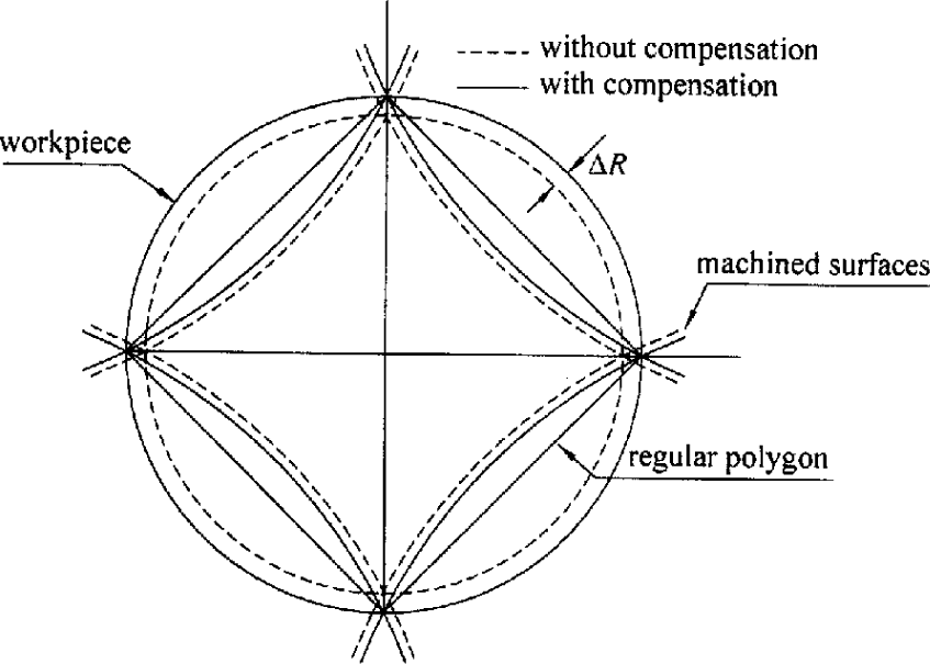
Schematic diagram showing effects of proposed compensation method.
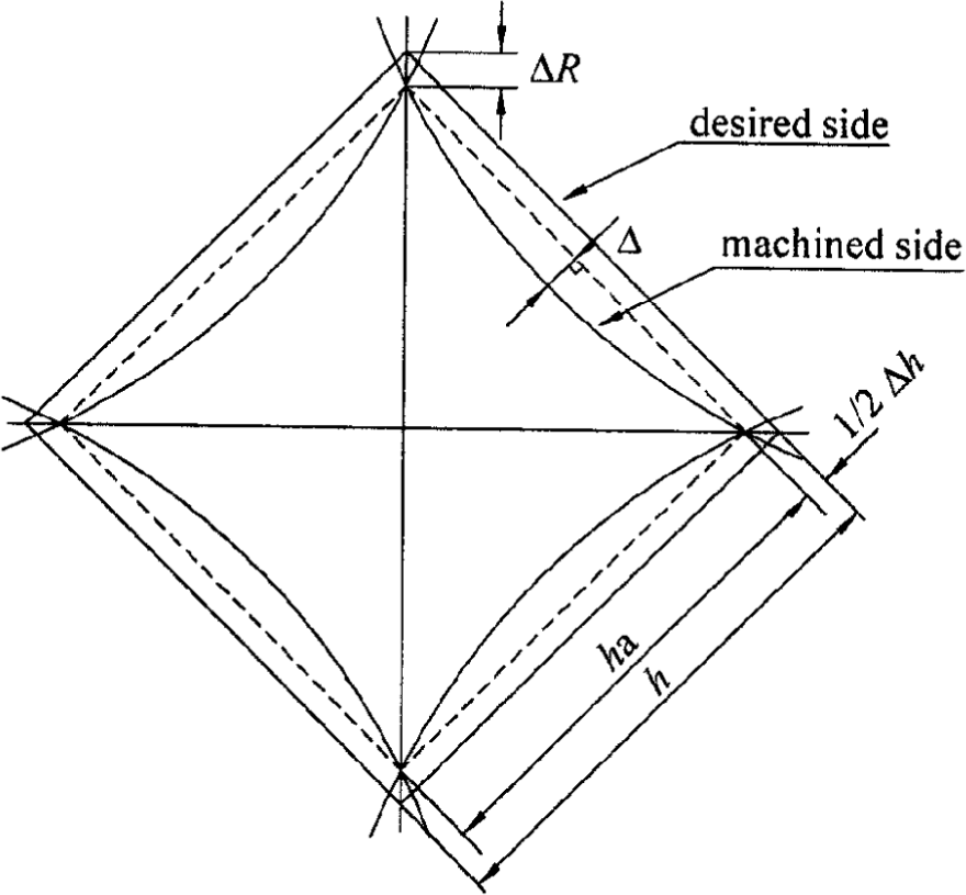
Schematic diagram of characteristics errors.
Figure 5 illustrates the characteristic errors of the proposed rotary machining method. Note that
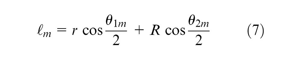
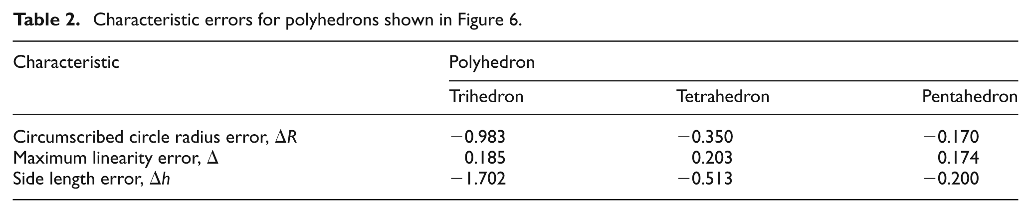
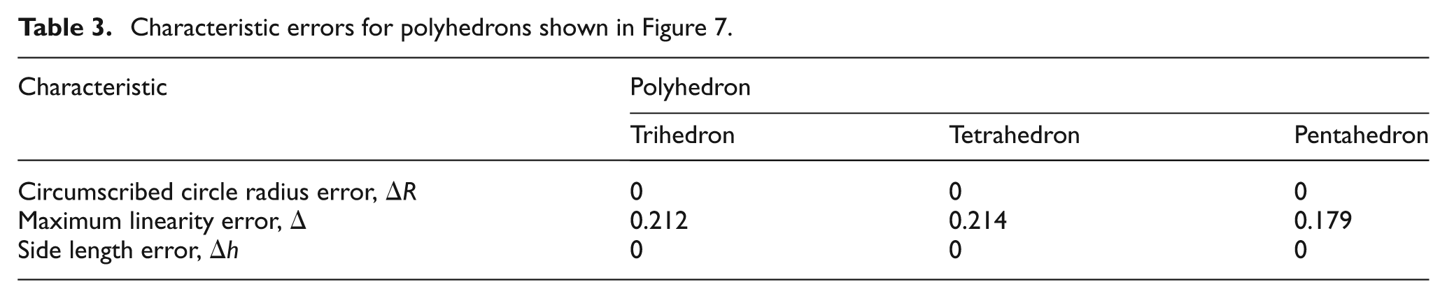
To evaluate the effectiveness of the proposed compensation scheme, the kinematic model presented in Section “Kinematic modeling of rotary cutting of polyhedron parts” was used to simulate the machining of trihedron, tetrahedron and pentahedron components given machining parameters of R = 15 mm and r = 125 mm. The components were machined initially using the center distance calculated using equation (4) (i.e. the non-compensated separation distance). The corresponding simulation results are presented in Figure 6(a)–(c), respectively. (Note that for the sake of clarity, the tool trajectory is only partially shown.) Table 2 shows the characteristic errors of the three components. It is observed that the trihedron component has the largest errors of the three polyhedrons. Figure 7(a)–(c) shows the profiles of the polyhedrons machined using the compensated center separation distance given in equation (7). Note that the incremental step size used in the compensation process has values of
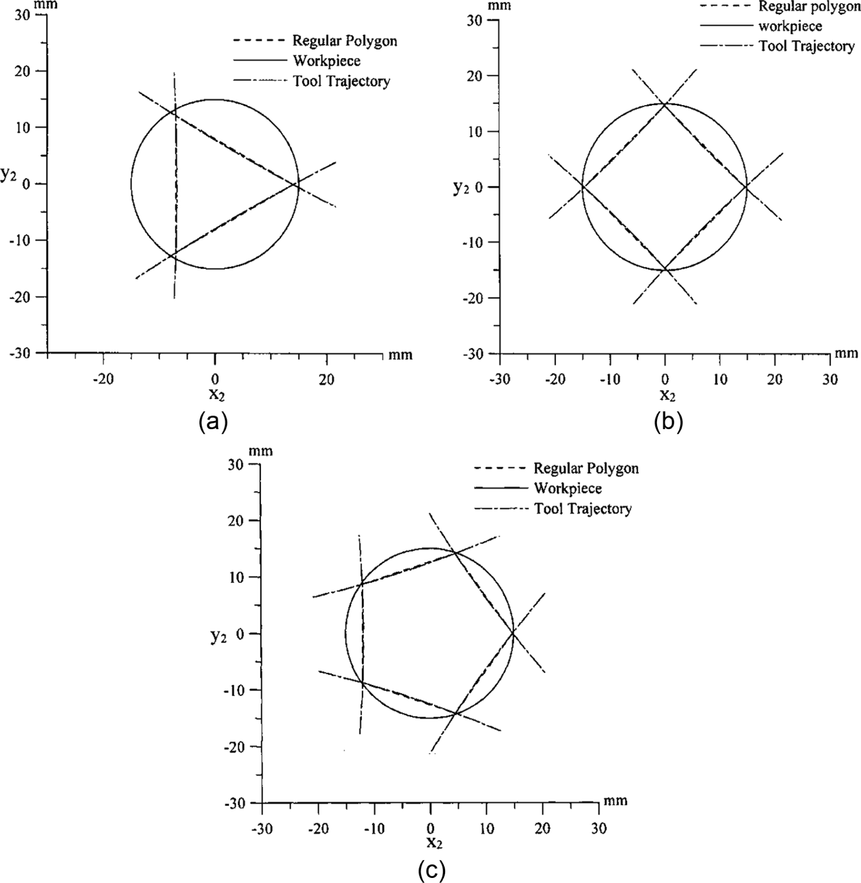
Polyhedron profiles obtained using constant angular speed method without center distance compensation: (a) trihedron, (b) tetrahedron and (c) pentahedron.
Characteristic errors for polyhedrons shown in Figure 6.
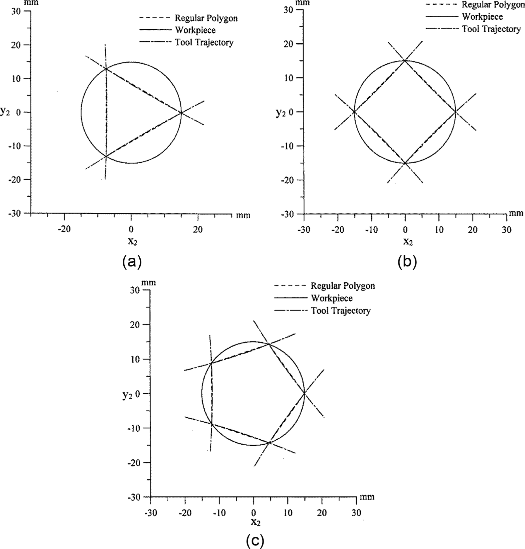
Polyhedron profiles obtained using center distance compensation: (a) trihedron, (b) tetrahedron and (c) pentahedron.
Characteristic errors for polyhedrons shown in Figure 7.
Conclusion
The following conclusions are drawn:
This article has proposed a mathematical model based on a constant angular velocity assumption for the rotary machining of polyhedron components. The proposed model allows for the complete machining of the polyhedron part in a single operation (i.e. a single setup process), and thus, the machining efficiency is significantly improved.
A method has been proposed for improving the dimensional accuracy of the machined polyhedron profile by incrementally adjusting the separation distance between the centers of the rotating workpiece and tool during the machining process.
The validity of the proposed machining and error compensation methodology has been demonstrated numerically for polyhedron components with n = 3, 4 and 5 sides. Overall, the results have shown that the proposed method provides a straightforward, efficient and accurate means of fabricating a wide variety of polyhedron components.
Footnotes
Appendix 1
Declaration of conflicting interests
The author declares that there is no conflict of interest.
Funding
This study was financially supported by the National Science Council of Taiwan under grant no. NSC101-2221-E-269-003.