
Abstract
Undesirable burrs are created out of a machining process. The objective of the present work is to explore the suitable condition to obtain no burr, or negligible burr, around the edge of a machined product at wet condition. Face milling experiments have been carried out on blocks made of aluminum alloy (Alloy-4600M) with a single, coated-carbide inserted cutter for observing the nature of burr formation. Depth of cut has been maintained constant at 3 mm for all sets of experiments. In each experiment set, three cutting velocities (170 m/min, 237 m/min and 339 m/min) and three in-plane exit angles of 30°, 60° and 90° are provided at three different feeds of 0.08 mm/tooth, 0.1 mm/tooth and 0.12 mm/tooth. First set of experiments are done without any exit edge bevel. Similar sets of experiments are carried out with 15° and 30° exit edge bevel angles to find out the condition for minimum burr. The bevel is made of a height of 3 mm. In the present experimental investigation, a minimum burr height of as low as 3 micron is obtained at an in-plane exit angle of 30° and exit edge bevel angle of 15° under the machining condition of 339 m/min cutting velocity and 0.1 mm/tooth feed.
Introduction
Machining processes commonly experience presence of burrs. Existence of burrs in a workpiece may cause several problems in a production line and involves sizeable production cost for its removal. Burr formation may not be completely prevented; however, substantial reduction of size of burr can be possible by adopting some ways and means.1–3
Many investigations on burr formation and its elimination or reduction were performed in the past. Olvera and Barrow 4 experimentally observed burr formation during square shoulder facing mailing operation, while Narayanaswami and Dornfeld 5 worked on various exit and entry side geometrical features of milling cutter-workpiece interactions and reported to have reduced length of burrs formed by at least 30% by adjusting geometrical parameters. An experimental observation was also made 6 to reduce burr formation in which edge bevelling had been made on the coated carbide cutting tool insert during high production rate milling operation, whereas a typical tool path was recommended7,8 to avoid tool exit in order to suppress exit burr to a great extent.
Hashimura et al. carried out 9 in-depth investigation on the effect of in-plane exit angle and rake angle on height and thickness of burrs in face milling operation, when Avila and Dornfeld explored 10 burr formation mechanism and reported to have small burr during milling through implementing a strategy of high tool engagement. Different other reports from this same group detailed on the influence of back cutting and tool wearing on burrs in face milling, 11 effect of milling on different materials like aluminium-silicon alloys and cast iron on the formation of burrs, 12 contribution of dry milling on burrs formed, 13 etc.
De Souza et al. 14 in a different work carried out high velocity milling operation using cBN cutting tools to report remarkable reduction of burrs apart from obtaining good surface finish. In one work, process control chart was made 15 for predicting burr formation and tool life, and to minimize burr size. Avila et al. reported 16 a detailed recommendation on minimization of burrs in aerospace and automotive component manufacturing, whereas Chern 17 investigated on burr formation mechanisms in face milling process, and influence of cutting conditions on burr formation in three different aluminum alloys. Burr geometry was found to be strongly dependent upon in-plane exit angle. Formation mechanisms of five types of burrs observed were explored and a guideline was suggested to reduce burr size effectively through the formation of secondary burr. An intelligent system was also developed by Kim et al. 18 to find the ways to have minimum burrs in face milling. Tripathi and Dornfeld employed 19 geometric solutions by modifying tool engagement conditions while Lee and Dornfeld 20 made use of artificial neural networks to predict burr types during face milling of aluminium alloy 6061-T6. In a different type of research work, Heisel et al. 21 experimented on burr formation in face milling under minimum quantity lubrication system, while minimization of burrs by optimizing cutting conditions was reported 22 to have achieved in face milling of mould steel. In a different type of work, the method of finding out size of burr using an image processing technique was discussed by Sharan and Onwubolu. 23
Series of investigations on controlling milling burr were done by another group lead by Das.24–31 They could reduce burr in 45C8 medium carbon steel,24,29,30 EN-25 nickel-chromium alloy steel,25,27 4600-M aluminum alloy 26 and commercial aluminium blocks28,31 either by bevelling exit edge by 15° and/or providing in-plane exit angle of 30° or 60°. They varied cutting conditions under dry environment to find out the condition to have minimum burr height.
Apart from the above, a number of other investigations32–36 was carried out on burr minimization in face milling. Different factors governing burr formation were explored 32 during high-speed milling of wrought aluminum alloys by Niknam and Songmene. da Silva et al. investigated 33 on burr dimensions in face milling of stainless steel. Tool geometry and radial depth were found to affect burr height the most, but the method of cutting fluid application was experienced to have little effect on burrs. Poka et al. 34 evaluated an optimal range of exit angle through experimental results corresponding to the path of the cutter such that burr formation would be small. Niknam and Songmene, 35 in another work, tried to correlate cutting force and acoustic emission signals with regard to slot milling burrs, top-up milling side burrs and exit burrs. They observed burrs along up milling side were the largest and thickest. In a more recent work, Su et al. 36 conferred from the experimental results that the type of cutting burrs on the exit side of the machined surface was influenced by machining conditions, and the optimized machining parameters were found out to be a cutting velocity of 800 m/min, feed of 0.25 mm/rev, and exit angle of 60°.
Finite Element Method based stress analysis was also utilized37,38 to evaluate the condition for controlling burr. While Park and Dornfeld did 37 finite element analysis to find out computationally the influence of exit angle, rake angle, and back up material on burr formation, Shyu carried out 38 finite element analysis based simulation of burr formation in face milling successfully. An overview of different analysis works based on FEM was also made in a review report on burrs and their control. 1
Recently a lot of works was focused39–41 on formation and control of burrs during micro-milling operation. Li et al. 40 applied controlled vibration to effectively suppress exit burr formation and to improve surface quality in 6061 aluminum alloy, while another work 39 was concentrated on modelling burr thickness while micro-end milling Ti6Al4V type titanium alloy. They could reduce prediction error substantially by including machining temperature in to the model. On the other hand, Kumar and Bajpai 41 worked on the same titanium alloy to observe top burr formed through micro-end milling operation. They reported a decrease in height of top burrs by about 50% while resorting to down milling operation when milling speed was increased to a high speed; up milling, however, showed large increase in burr height.
In the present work, effects of exit edge bevel, in-plane exit angle and cutting conditions on burr formation in face milling of an aluminium alloy are explored under wet condition to explore the condition to have minimum burr formation.
Experimental details
Experiments are carried out on a vertical axis BFW CNC milling machine to perform face milling on aluminum alloy (Alloy- 4600M) blocks with single inserted coated carbide tool on a 54 mm diameter cutter (Figure 1(a) and (b)) for observing nature of burr formation. Depth of cut (t) is maintained at 3 mm throughout this investigation under wet condition using water soluble oil (water: Blasocut Combi oil = 15:1).
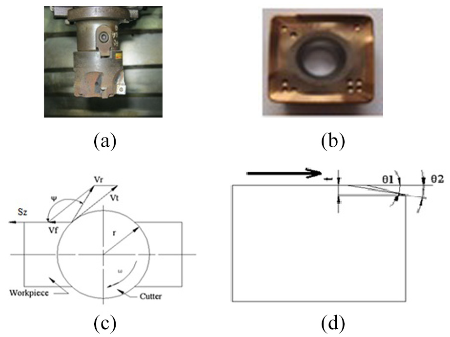
(a) The cutter used, (b) the insert used, (c) definition of exit-edge bevel angle, θ (t: depth of cut, θ1, θ2: two different values of exit-edge bevel angle, when θ1 < θ2. Arrow head indicates direction of cutting velocity of cutter), and (d) definition of in-plane exit angle, ψ (r: radius of cutter, ω: angular speed, Vf: feed velocity, Vt: tangential velocity of cutter at the exit edge, Vr: resultant velocity of cutter at the exit edge, Sz: feed of the cutter relative to the workpiece).
In dry condition, it was found24–27 that at an exit edge bevel angle (Figure 1(c)) of 15°, quite small burrs occurred, while Saha et al. 24 observed negligible burrs at 60° in-plane exit angle (Figure 1(d)) with an exit edge bevel angle of 15°. Keeping these in mind, in each experiment set, first, in-plane exit angle is varied from 30° to 90° at a step of 30° with respect to three different feeds (Sz) of 0.08 mm/tooth, 0.1 mm/tooth and 0.12 mm/tooth. Then, this set of experiments is carried out at three different cutting velocities (Vc) of 339 m/min, 237 m/min and 170 m/min without any exit edge bevel angle to find out the condition for minimum burr formation. Next, all these sets of experiments are performed with 15° and 30° exit edge bevel angle. Beveling is done using a shaping machine and it is made to have a maximum depth of 3 mm. Burr height of machined exit edge is measured under a Mitutoyo, Japan made tool makers microscope (Model No.: T510).
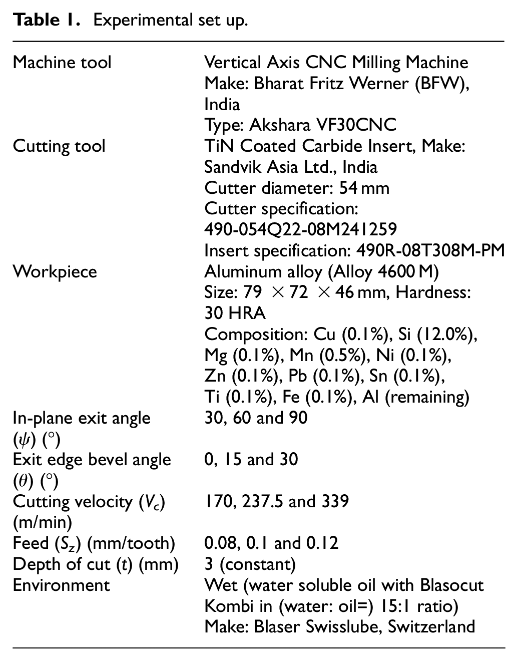
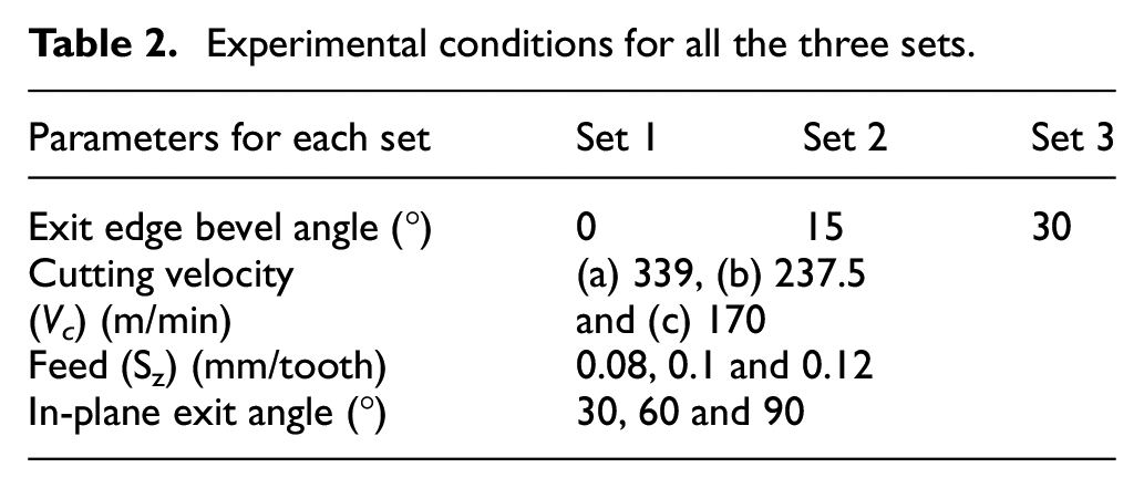
Detail of experimental set-up is shown in Table 1. Cutting conditions are shown in Table 2 for experiment set 1, 2 and 3 with 339 m/min, 237.5 m/min and 170 m/min cutting velocity.
Experimental set up.
Experimental conditions for all the three sets.
Results and discussion
Experimental investigation for set 1 without edge bevel
Experiment set 1 is carried out without any exit edge bevel in wet condition at three levels of cutting velocity (Vc), feed (Sz) and in-plane exit angle as outlined in Table 2.
Experimental investigation for set 1(a) without edge bevel
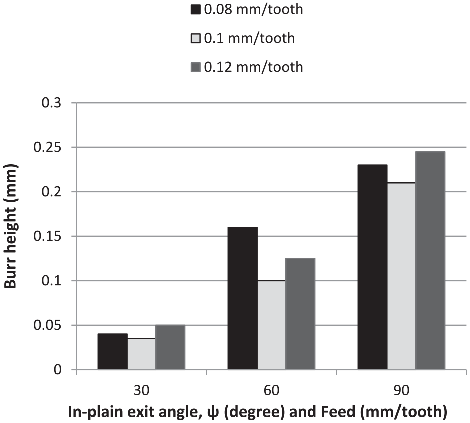
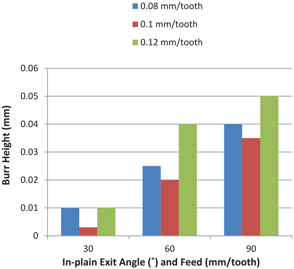
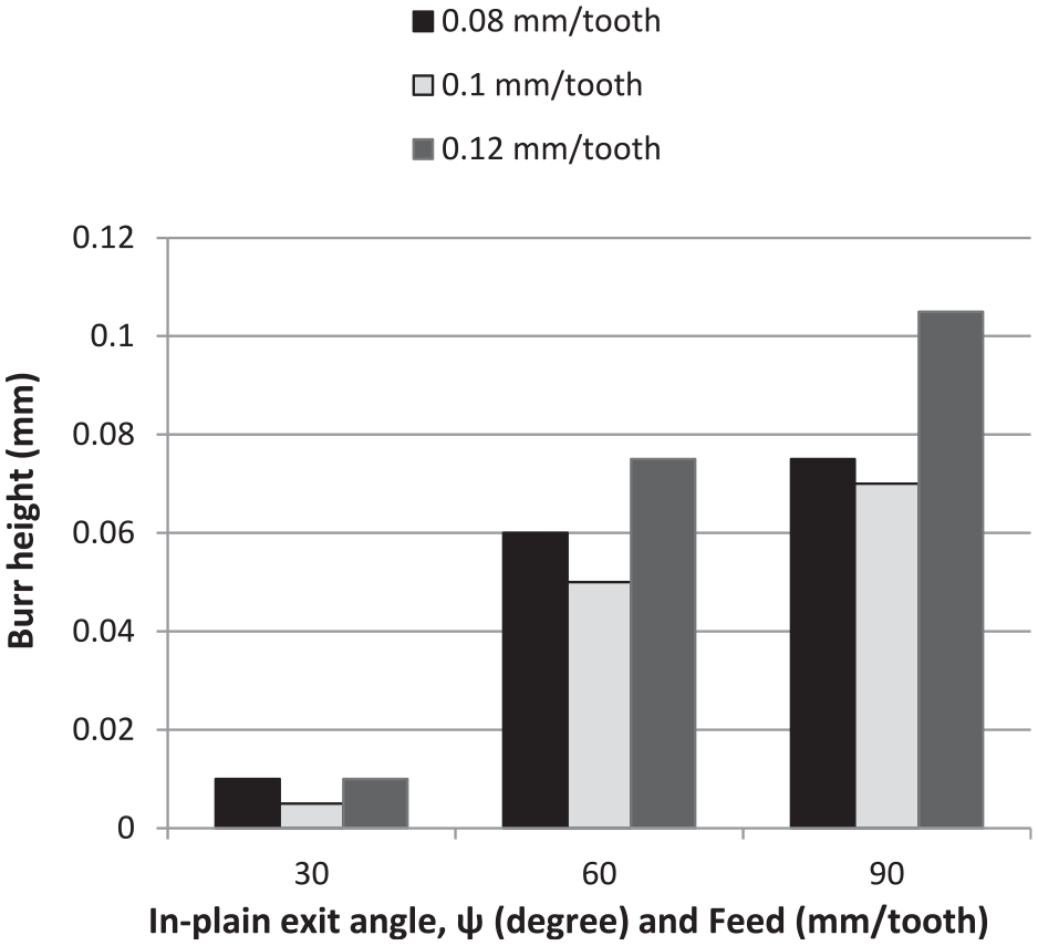
Experiment set 1(a) is performed with a cutting velocity (Vc) of 339 m/min. Feed (Sz) and in-plane exit angle are varied thrice without exit edge bevel. Corresponding burr heights are measured and are shown in Figure 2.
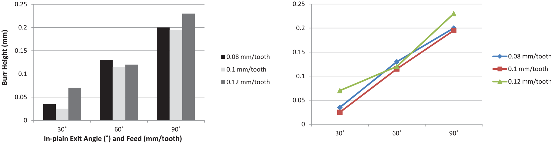
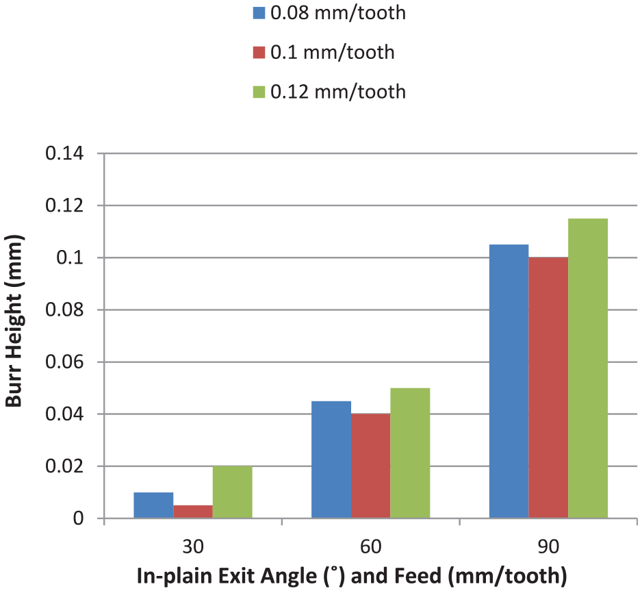
Variation of average height of burrs for set 1(a).
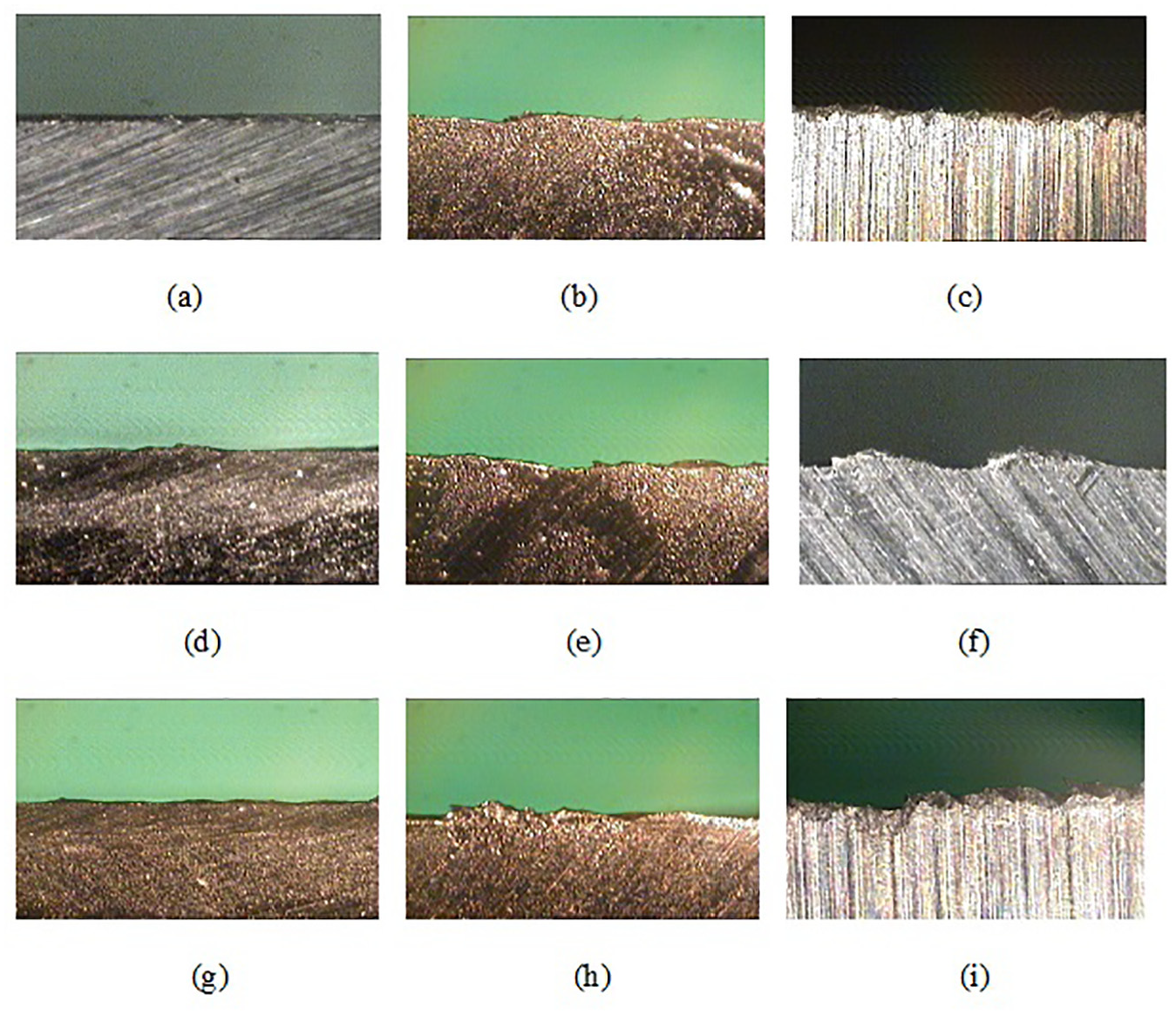
From Figure 2, it is found out that burr height at the exit edge is much less at 30° in-plane exit angle under all the three feeds chosen. Among all the three feeds, 0.1 mm/tooth feed gives the least burr height. Microscopic views of burrs are shown in Figure 3(a) to (i).
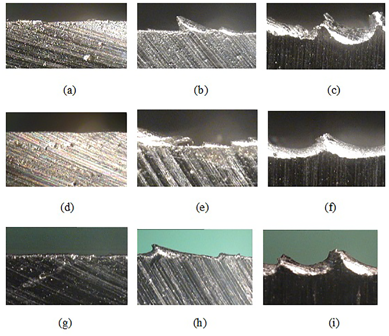
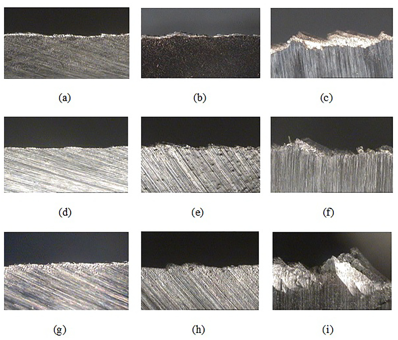
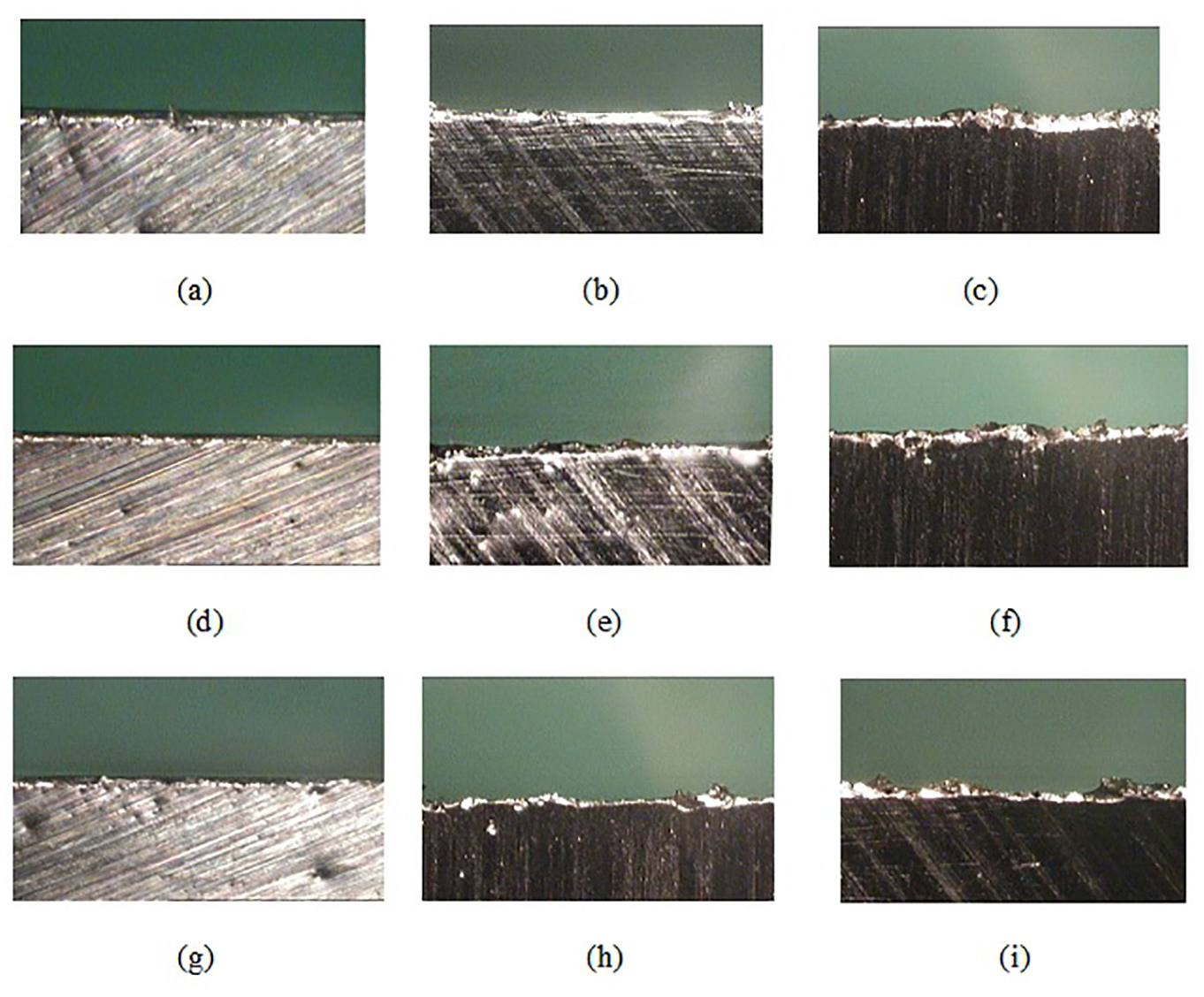
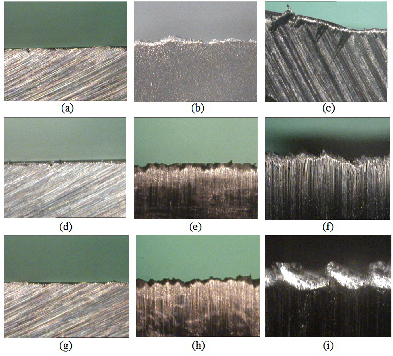
Microscopic views of burrs for in-plane exit angle and feed of: (a) 30° and 0.08 mm/tooth, (b) 60° and 0.08 mm/tooth, (c) 90° and 0.08 mm/tooth, (d) 30° and 0.1 mm/tooth, (e) 60° and 0.1 mm/tooth, (f) 90° and 0.1 mm/tooth, (g) 30° and 0.12 mm/tooth, (h) 60° and 0.12 mm/tooth, and (i) 90° and 0.12 mm/tooth respectively for experiment set 1(a).
At a low in-plane exit angle, the need of backup support material is less, and therefore, the chance of burr formation is expected to be less.1,4,15,27–29,31 Burr height observed is also expectedly low as seen in the present work at 30° in-plane exit angle. At 30° in- plane exit angle corresponding to three feed values, quite small burrs are seen in Figure 3(a), (d) and (g). At high in-feed of 0.12 mm/tooth, distinct saw type burrs are seen (Figure 3(i)). Figure 3(e), (f) and (h) also show narrow saw tooth type burrs. Burr height observed at these conditions is somewhat smaller than that reported 26 in dry condition. Under wet condition, machining temperature is expected to be much reduced compared to that under dry condition due to the application of the cutting fluid, and therefore, ductility of the workpiece during wet machining would not become high as that at dry condition where thermal softening is likely to take place to some extent. When ductility is high, formation of exit burr is expected to be high due to transformation of shear plane from the positive shear angle to negative shear angle. For this reason, wet milling probably shows low burr height formation.
Experimental investigation for set 1(b) without edge bevel
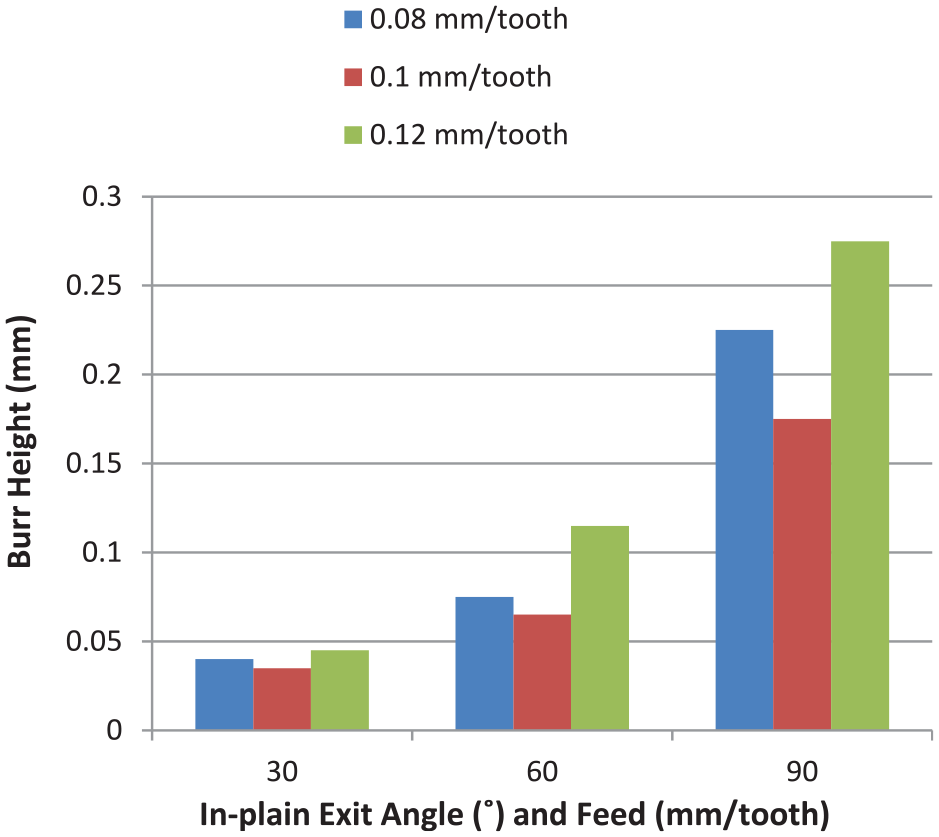
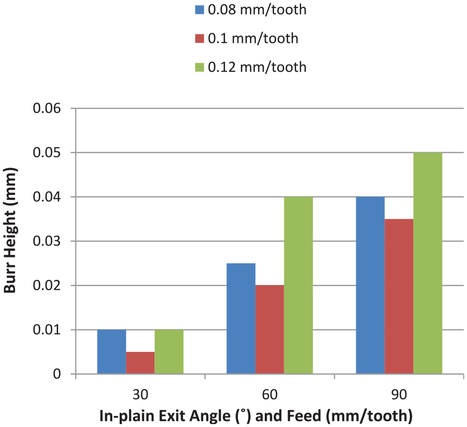
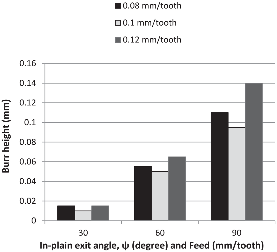
In experiment set 1(b), cutting velocity of 237.5 m/min is taken. Feed and in-plane exit angle are varied three times similar to experiment set 1(a). Burr heights measured are presented in Figure 4. Microscopic views of burrs are shown in Figure 5(a) to (i).
Variation of average height of burrs for experiment set 1(b).
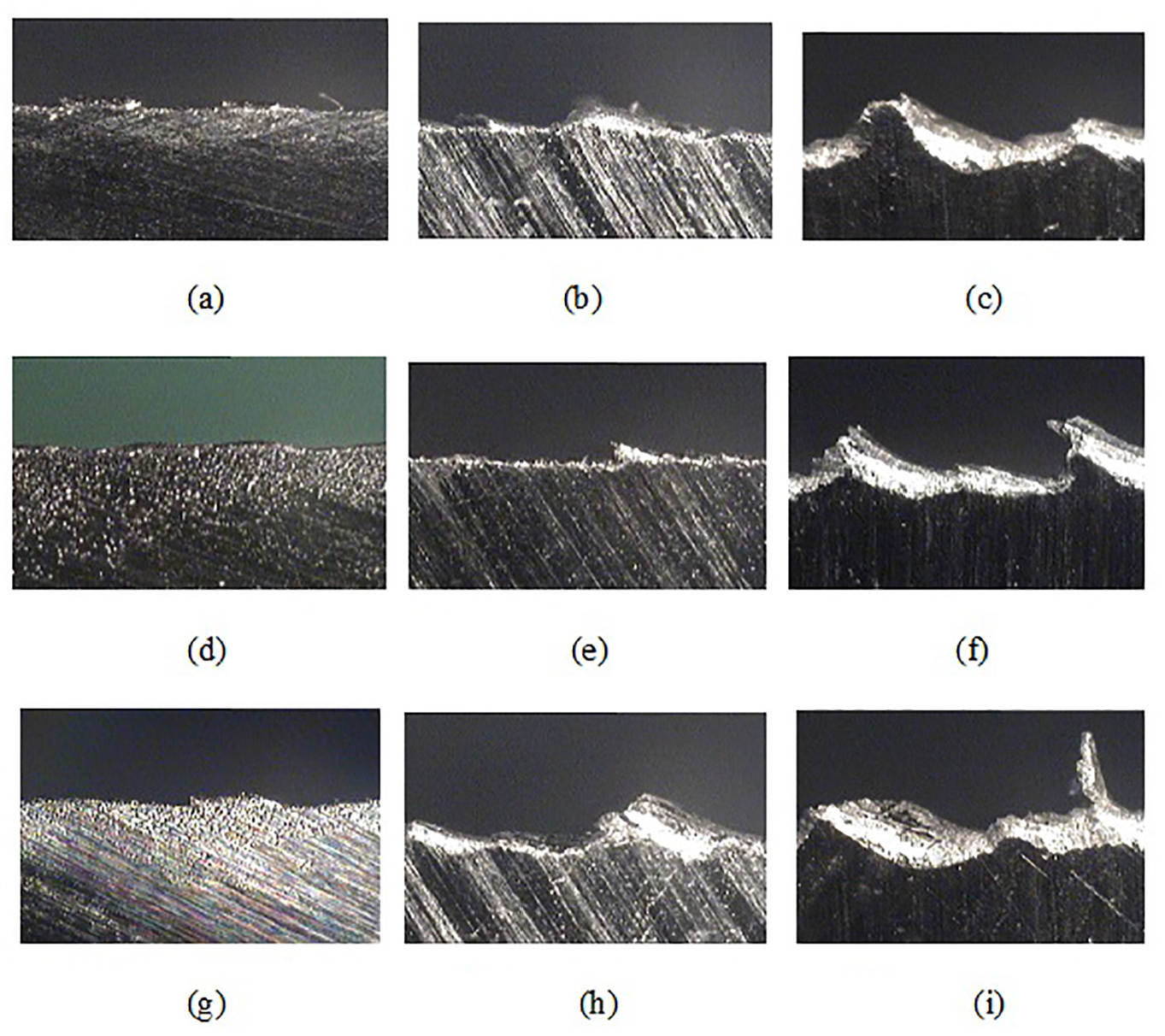
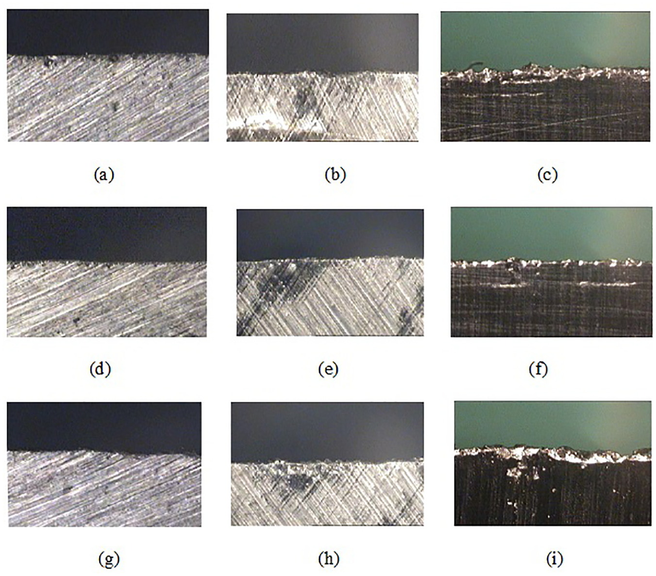
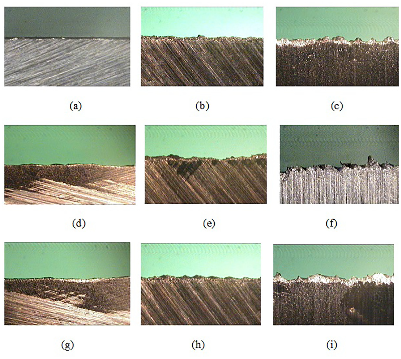
Microscopic views of burrs for in-plane exit angle and feed of: (a) 30° and 0.08 mm/tooth, (b) 60° and 0.08 mm/tooth, (c) 90° and 0.08 mm/tooth, (d) 30° and 0.1 mm/tooth, (e) 60° and 0.1 mm/tooth, (f) 90° and 0.1 mm/tooth, (g) 30° and 0.12 mm/tooth, (h) 60° and 0.12 mm/tooth, and (i) 90° and 0.12 mm/tooth respectively of experiment set 1(b).
From Figure 4, it is found out that burr height at the exit edge is less than 50 µm at 30° in-plane exit angle, under 237.5 m/min cutting velocity without any edge bevel. Among all the three feeds, 0.1 mm/tooth feed gives the least burr height.
Figure 5(a) to (i) show photographs of burrs formed at experiment set 1(b). At a low in-plane exit angle, the need of backup support material is less, and therefore, the chance of burr formation becomes less. For this reason, burr observed is expectedly quite small as seen in the present experiment set at 30° in-plane exit angle. Similar observations were also reported previously.27–29,31 At 30° in-plane exit angle corresponding to three feed values, quite small burrs are seen as depicted in Figure 5(a), (d) and (g). At the high in-plane exit angle of 90°, distinct saw type burrs are seen (at Figure 5(c), (f) and (i)). Figure 5(b), (e) and (h) show no prominent saw tooth type burr.
Experimental investigation for set 1(c) without edge bevel
In this set of experiment, a low cutting velocity of 170 m/min is taken; details are shown in Table 2. Burr heights measured are presented in Figure 6. Microscopic views of burrs are shown in Figure 7(a) to (i).
Variation of average height of burrs for set 1(c).
Microscopic views of burrs for in-plane exit angle and feed of: (a) 30° and 0.08 mm/tooth, (b) 60° and 0.08 mm/tooth, (c) 90° and 0.08 mm/tooth, (d) 30° and 0.1 mm/tooth, (e) 60° and 0.1 mm/tooth, (f) 90° and 0.1 mm/tooth, (g) 30° and 0.12 mm/tooth, (h) 60° and 0.12 mm/tooth, and (i) 90° and 0.12 mm/tooth respectively of experiment set 1(c).
From Figure 6, it is also found out that burr height at the exit edge is quite less at 30° in-plane exit angle similar to set 1(a and b), under 170 m/min cutting velocity under at the three feeds without any edge bevel. Among all the three feeds, 0.1 mm/tooth feed condition gives the least burr height.
Figure 7(a) to (i) show photographs of burrs formed at experiment set 1(c). At a low in-plane exit angle, as discussed earlier, the need of backup support material is less, and therefore, there is less chance of burr formation. For this, burr form observed is expectedly less as seen in the present work at 30° in-plane exit angle. At 30° in-plane exit angle, corresponding to three feed values, quite less burr height is seen in Figure 7(a), (d) and (g). At a high in-plane exit angle of 90°, distinct saw type burrs are seen (Figure 7(c), (f) and (i)). Figure 7(f) shows no saw tooth type burrs.
Experimental investigation for set 2 with edge bevel angle of 15°
Face milling is also carried out on 4600M aluminum alloy test pieces in this experiment set 2 but with an exit edge bevel angle of 15°. Other conditions are kept similar to previous set of experiments as detailed in Table 2.
Experimental investigation for set 2(a) with edge bevel angle of 15°
In experimental set 2(a), at a cutting velocity of 339 m/min, feed and in-plane exit angle are varied three times by providing 15° exit edge bevel angle. Burr heights measured are presented in Figure 8. Microscopic views of burrs are shown in Figure 9(a) to (i).
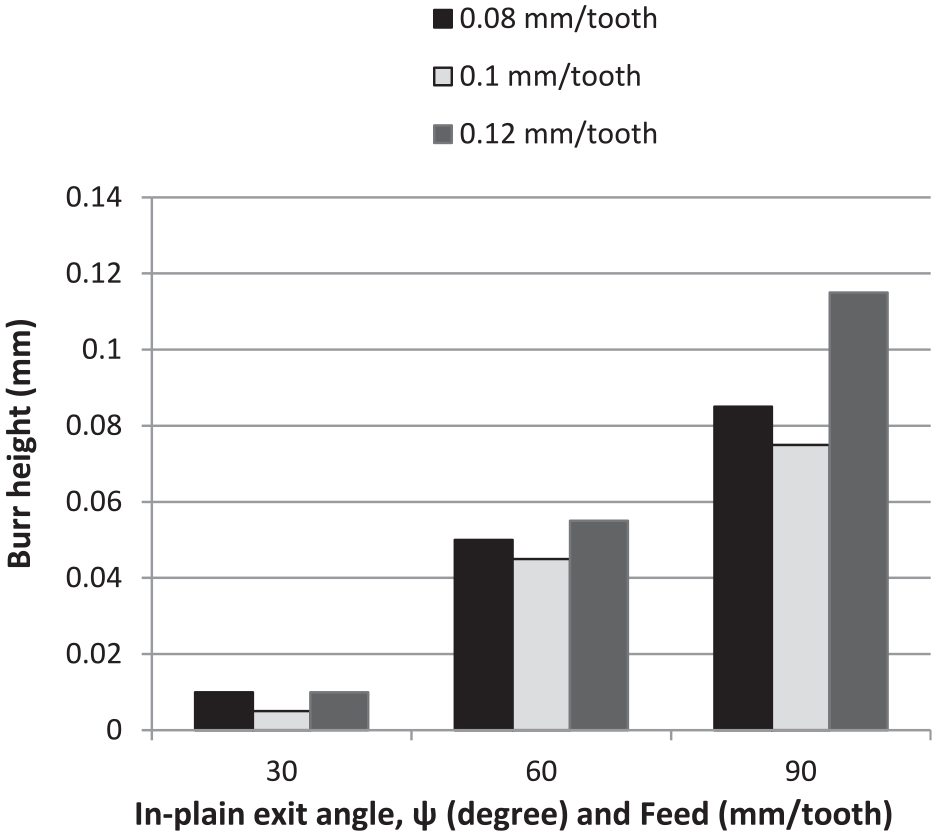
Variation of average height of burrs for set 2(a).
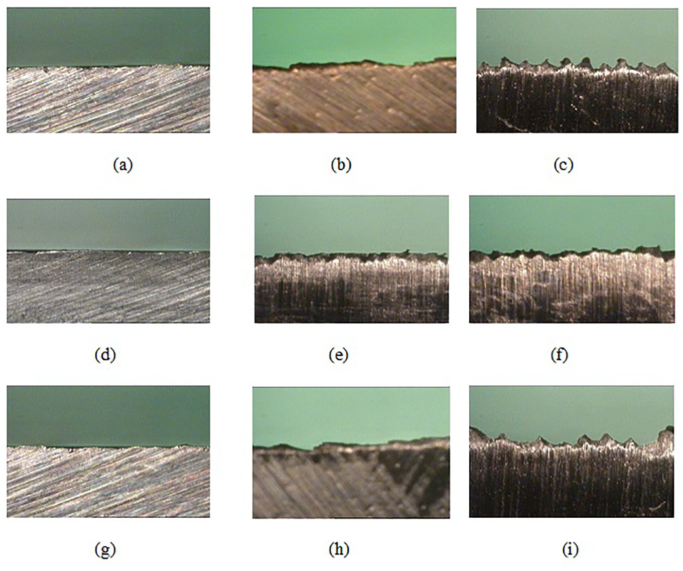
Microscopic views of burrs for in-plane exit angle and feed of: (a) 30° and 0.08 mm/tooth, (b) 60° and 0.08 mm/tooth, (c) 90° and 0.08 mm/tooth, (d) 30° and 0.1 mm/tooth, (e) 60° and 0.1 mm/tooth, (f) 90° and 0.1 mm/tooth, (g) 30° and 0.12 mm/tooth, (h) 60° and 0.12 mm/tooth, and (i) 90° and 0.12 mm/tooth respectively of experiment set 2(a).
From Figure 8, it is found out that burr height at the exit edge is quite less at 30° in-plane exit angle, under 339 m/min cutting velocity at the three feeds chosen with an exit edge bevel angle of 15°. Due to 15° exit edge bevel angle, burr height is significantly lesser than that of experimental set 1. This is expected as the cutter approaches the exit edge along the bevel edge, depth of cut reduces gradually needing gradually reducing cutting force. Similar observation was also reported in earlier findings.24–26,30 Among all the three feeds, 0.1 mm/tooth feed condition gives the smallest burrs.
Figure 9(a) to (i) show photographs of burrs formed at experiment set 2(a). In this set of experiment, exit edge bevelled of 15° is used along with 30° in-plane exit angle, and may be due to this, burr height is significantly less. At a low in-plane exit angle, as well as with bevelled exit edge, the need of backup support material is less, and therefore, there is chance of less burr formation. At 30° in-plane exit angle corresponding to three feed values, quite less burrs are visible in Figure 9(d) at 0.1 mm/tooth feed.
Experimental investigation for set 2(b) with exit edge bevel angle of 15°
Experimental set 2(b) is performed at a cutting velocity of 237.3 m/min with an exit edge bevel angle of 15°. Burr heights measured are presented Figure 10. Microscopic views of burrs are shown in Figure 11(a) to (i).
Variation of average height of burrs for set 2(b).
Microscopic views of burrs for in-plane exit angle and feed of: (a) 30° and 0.08 mm/tooth, (b) 60° and 0.08 mm/tooth, (c) 90° and 0.08 mm/tooth, (d) 30° and 0.1 mm/tooth, (e) 60° and 0.1 mm/tooth, (f) 90° and 0.1 mm/tooth, (g) 30° and 0.12 mm/tooth, (h) 60° and 0.12 mm/tooth, and (i) 90° and 0.12 mm/tooth respectively of experiment set 2(b).
From Figure 10, it is found out that burr height at the exit edge is quite less at 30° in-plane exit angle, at 237.5 m/min cutting velocity and three feeds selected with an exit edge bevel angle of 15°, and may be due to 15° exit edge bevel angle along with 30° in-plane exit angle, burr height is significantly lesser than that of experiment set 1(b). Among all the three feeds, 0.1 mm/tooth feed condition gives the least burr height.
Figure 11(a) to (i) show photographs of burrs formed at experiment set 2(b). In this set of experiment, exit edge of workpiece is bevelled with 15°θ, and may be due to this and 30°ψ, burr height is remarkably less. At a low in-plane exit angle and 15° edge bevel, the need of backup support material is less, and therefore, the chance of burr formation may be negligible.
Experimental investigation for set 2(c) with exit edge bevel angle of 15°
In this set of experiment, cutting velocity used is 170 m/min, and other machining conditions are shown in Table 2. Burr heights measured are presented in Figure 12. Microscopic views of burrs are shown in Figure 13(a) to (i).
Variation of average height of burrs for set 3(c).
Microscopic views of burrs for in-plane exit angle and feed of: (a) 30° and 0.08 mm/tooth, (b) 60° and 0.08 mm/tooth, (c) 90° and 0.08 mm/tooth, (d) 30° and 0.1 mm/tooth, (e) 60° and 0.1 mm/tooth, (f) 90° and 0.1 mm/tooth, (g) 30° and 0.12 mm/tooth, (h) 60° and 0.12 mm/tooth, and (i) 90° and 0.12 mm/tooth respectively of experiment set 2(c).
From Figure 12, it is found out that burr height at the exit edge is quite less at 30° in-plane exit angle at 170 m/min cutting velocity with exit edge bevel angle (θ) of 15°. May be due to 15° exit edge bevel angle and 30°ψ, burr height is remarkably lesser than that at set 1(c). Among all the three feeds, 0.1 mm/tooth feed condition shows the smallest burr height.
Figure 13(a) to (i) show photographs of burrs formed at experiment set 2(c). In this set of experiment, exit edge is bevelled with 15°θ, and may be due to this and 30°ψ, burr height becomes quite less as discussed earlier. At 30° in-plane exit angle, corresponding to three feed values, quite less burrs are seen in Figure 13(a), (d) and (g).
Experimental investigation for set 3 with exit edge bevel angle of 30°
Experiment set 3 is performed with exit edge bevel of 30°. Other conditions remain similar to the other two sets of experiments. Table 2 outlines the experimental detail of this set.
Experimental investigation for set 3(a) with exit edge bevel angle of 30°
In experimental set 3(a), at a cutting velocity (Vc) of 339 m/min, feed (Sz) and in-plane exit angle are varied three times with a provision of 30° exit edge bevel angle. Burr heights measured are presented in Figure 14. Microscopic views of burrs are shown in Figure 15(a) to (i).
Variation of average height of burrs for set 3(a).
Microscopic views of burrs for in-plane exit angle and feed of: (a) 30° and 0.08 mm/tooth, (b) 60° and 0.08 mm/tooth, (c) 90° and 0.08 mm/tooth, (d) 30° and 0.1 mm/tooth, (e) 60° and 0.1 mm/tooth, (f) 90° and 0.1 mm/tooth, (g) 30° and 0.12 mm/tooth, (h) 60° and 0.12 mm/tooth, and (i) 90° and 0.12 mm/tooth respectively of experiment set 3(a).
From Figure 14, it is found out that burr height at the exit edge is quite less at 30° in-plane exit angle, under 339 m/min cutting velocity at all the three feeds with 30° exit edge bevel angle. At 30° exit edge bevel angle and 30° in-plane exit angle, edge burr height is remarkably lesser than that of set 1, however, it is not less then set 2. Among all the three feeds, 0.1 mm/tooth feed condition gives the lowest burr height.
Figure 15(a) to (i) show photographs of burrs formed at experiment set 3(a). In this set of experiment, exit edge is bevelled at an angle of 30°, and due to this, burr height is significantly less. At a low in-plane exit angle, the need of backup support material is also less, and therefore, the chance of burr formation is negligible. As a result, burr form observed is expectedly less as seen in the present work at 30° in-plane exit angle. At 30° in-plane exit angle, corresponding to three feeds, quite less burrs are seen in Figure 15(a), (d) and (g). Figure 15(c), (f) and (i) show slightly larger size of burrs than that shown in Figure 15(a), (d) and (g).
Experimental investigation for set 3(b) with exit edge bevel angle of 30°
Experiment Set 3(b) is performed at a cutting velocity (Vc) of 237.5 m/min keeping other conditions as that of set 3(a). Burr heights seen at different conditions are presented in Figure 16. Microscopic views of burrs are shown in Figure 17(a) to (i).
Variation of average height of burrs for set 3(b).
Microscopic views of burrs for in-plane exit angle and feed of: (a) 30° and 0.08 mm/tooth, (b) 60° and 0.08 mm/tooth, (c) 90° and 0.08 mm/tooth, (d) 30° and 0.1 mm/tooth, (e) 60° and 0.1 mm/tooth, (f) 90° and 0.1 mm/tooth, (g) 30° and 0.12 mm/tooth, (h) 60° and 0.12 mm/tooth, and (i) 90° and 0.12 mm/tooth respectively of experiment set 3(b).
From Figure 16, it is found out that burr height at the exit edge is quite less of about 10 µm at 30° in-plane exit angle, under 237.5 m/min cutting velocity under at all the three feeds with exit edge bevel angle of 30°. Due to 30° exit edge bevel angle, burr height may be lesser than that at set 1, but not less than set 2. Among all the three feeds, 0.1 mm/tooth feed condition gives the least burr height.
Figure 17(a) to (i) show photographs of burrs formed at experiment set 3(b). In this set of experiment, exit edge is bevelled with 30°, and burr height is found to be significantly less. At a low in-plane exit angle, the need of backup support material is naturally less, and therefore, the chance of burr formation becomes less. As a result, burr form observed is expectedly less as seen in the present work at 30° in-plane exit angle. At 30° in-plane exit angle corresponding to three feed values, quite less burrs are seen in Figure 17(a), (d) and (g). Figure 17(c), (f) and (i) show narrow saw tooth type burrs.
Experimental investigation for set 3(c) with exit edge bevel angle of 30°
In this set of experiment, cutting velocity set is 170 m/min, and other machining conditions are shown in Table 2. Burr heights measured are presented in Figure 18. Microscopic views of burrs are shown in Figure 19(a) to (i).
Variation of average height of burrs for set 3(c).
Microscopic views of burrs for in-plane exit angle and feed of: (a) 30° and 0.08 mm/tooth, (b) 60° and 0.08 mm/tooth, (c) 90° and 0.08 mm/tooth, (d) 30° and 0.1 mm/tooth, (e) 60° and 0.1 mm/tooth, (f) 90° and 0.1 mm/tooth, (g) 30° and 0.12 mm/tooth, (h) 60° and 0.12 mm/tooth, and (i) 90° and 0.12 mm/tooth respectively of experiment set 3(c).
From Figure 18, it is found out that burr height at the exit edge is quite less at 30° in-plane exit angle, under 170 m/min cutting velocity at the three feeds with 30° exit edge bevel angle. Probably due to 30° exit edge bevel angle, burr height is lesser than experiment set 1, but not lesser than set 2. Among all the three feeds, medium feed of 0.1 mm/tooth gives the least burr height in this experiment.
Figure 19(a) to (i) show photographs of burrs formed at experiment set 3(c). In this set of experiment, exit edge is bevelled at 30°. At this set of experiment, burr height is significantly less. Low in-plane exit angle and edge bevelling reduce the need of backup support material, and naturally, there would be negligible chance of burr formation. As a result, burr form observed is expectedly less as seen in the present work at 30° in-plane exit angle with edge bevel. At 30° in-plane exit angle corresponding to three feed values, quite less burrs are seen as shown in Figure 19(a), (d) and (g). Figure 19(c), (f) and (i) show narrow saw tooth type burrs at an in-plane exit angle of 90°, when the least back-up support is available.
Conclusion
On the basis of the experimental investigation on face milling of aluminium alloy 4600 M block with TiN coated carbide tool inserts in wet condition, following conclusions may be drawn.
Among the three in-plane exit angles undertaken, an in-plane exit angle of 30° gives quite less burr formation under all the speed-feed conditions compared to other in-plane exit angles.
At the medium feed condition of 0.1 mm/tooth and high cutting velocity of 339 m/min, observed burr height at an in-plane exit angle of 30° for an exit edge bevel angle of 15° is found to be the lowest in this experimental work, and may be recommended for practice in industry.
At a low in-plane exit angle, the need of backup support material is less, and therefore, the chance of burr formation becomes negligible. Low exit edge bevel also reduces the requirement of backup support, due to gradual decrease in depth of cut. So, for this reason, burr formation is likely to be negligible at low in-plane exit angle, and at somewhat low exit edge bevel angle.
Footnotes
Appendix
Declaration of conflicting interests
The author(s) declared no potential conflicts of interest with respect to the research, authorship, and/or publication of this article.
Funding
The author(s) received no financial support for the research, authorship, and/or publication of this article.