
Abstract
Because of global competition, manufacturing industries today must provide high-quality products on time to remain competitive. High-quality mechanical parts include those with better surface finish and texture, dimension and form accuracies, reduced residual stress and burr-free. Burr formation is one of the most common and undesirable phenomenon occurring in machining operations, which reduces assembly and machined part quality. To remove burrs, a secondary operation known as deburring is required for post-processing and edge finishing operations. Since deburring is costly and considered a non-value-added process, the goal is desired to eliminate burrs or reduce the effort required to remove them. Because of non-uniform chip thickness, tool runout and complex interactive effects between cutting process parameters, milling burr formation is a very complex mechanism. Therefore, research and close attention are still needed in order to minimize and control milling burr formation. In this article, a review of burr formation and characterization is presented, along with burr formation modeling and control. An overview of factors governing milling burr formation is also presented.
Introduction
As manufacturing processes become increasingly advanced, precision components require more attention for both surface and edge generation. High-quality products must be precisely manufactured according to design specifications and at low manufacturing costs. To fulfill these requirements, the manufacturing process must be well understood, and its parameters optimized. This is especially true in the aerospace and automobile industries.
Burr formation, a phenomenon similar to chip generation, is a common problem that occurs in several industrial sectors, such as the aerospace and automobile sectors. It has also been among the most troublesome impediments to high productivity and automation and largely affects the machined part quality. To ensure competitiveness, precise and burr-free components with tight tolerances and better surface finish are demanded.
Intensive research conducted during the last decades has laid out the mechanisms of burr formation and deburring in a very comprehensive fashion and has introduced integrated strategies for burr prevention and minimization. Despite all the improvements realized, there are still many challenges encountered in understanding, modeling and optimizing the burr formation process and size, through production growth and cycle time reduction.
Among machining burrs, milling burr formation involves a more complex mechanism (multiple burrs formed at different locations and with varying shapes and sizes). This leads to numerous difficulties during the deburring process, and therefore, it is extremely beneficial to limit and control milling burrs rather than deburring them in subsequent finishing operations. This could be achieved by burr size minimization or effective burr prevention through adequate understanding of the basic mechanisms of burr formation and an accurate proposal of optimum cutting parameters. Comprehensive knowledge of factors governing burr formation is thus essential in order to reduce the incidence of burr formation. Another approach for minimizing the burr size involves using models and simulation. To that end, the use of analytical, experimental and numerical methods is welcomed. This article presents a comprehensive overview of milling burr formation, definition, characterization, modeling, minimization and control.
Burr definitions and classification
Burr formation is one of the major issues currently facing manufacturing industries. Burr consists of an undesirable extended surface over the workpiece 1 or a missing portion on the workpiece edge (negative burr, see Figure 1), which should be avoided or at least minimized.
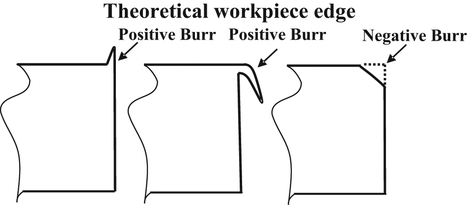
Examples of burr definition.
Pekelharing 2 was the first person to describe the burr formation mechanism in metal cutting. As can be seen in Figure 2, to better describe the burr, a new term called “burr value” was defined by Schäfer. 3 It contains the burr root thickness (br), burr height (bh), burr thickness (bt) and burr root radius (rf). However, measuring and/or estimating all these parameters to calculate the burr value is very difficult and time-consuming. Furthermore, it would appear that the burr value can also not be used as an efficient parameter to better select a deburring method. Of all the burr parameters, the burr height and thickness are used to determine the burr removal difficulties. 4
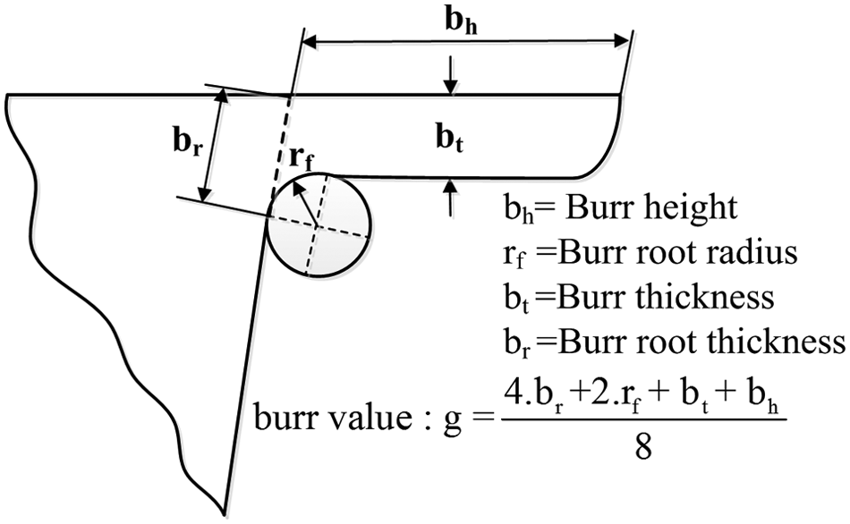
Measurement values of a burr.
Burrs can be excessively large and irregular (Figure 3(a)) or very small in size, even not visible to the naked eye (Figure 3(b)). Therefore, a proper understating of the burr formation mechanism and a correct selection of cutting parameter setting levels are recommended in order to reduce the incidence of burr formation and possibly improve the surface quality and tool life.
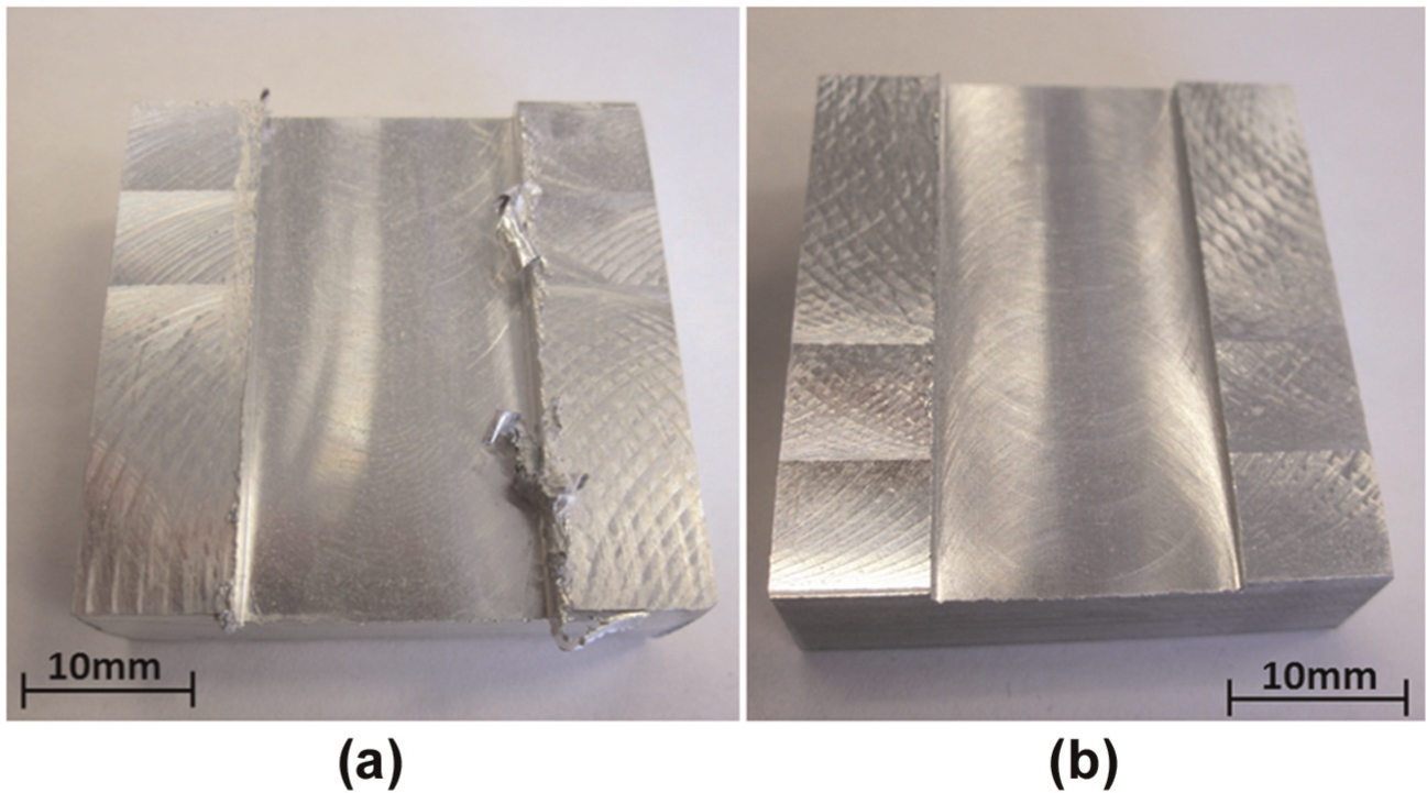
Slot-milled machined parts with (a) large burr formation and (b) burr formation with tiny scales.
Burr formation mechanism
Several authors have contributed to the advancement of knowledge on burr formation mechanisms, including Pekelharing, 2 Sofronas, 6 Gillespie, 7 Nakayama and Arai, 8 Chern and Dornfeld, 9 Hashimura et al.10,11 and Aurich et al. 12 According to Pekelharing, 2 negative shear is responsible for the exit failure of cutting tools and root type burrs in milling. The first fundamental work on burrs was published by Gillespie, 13 and he 13 developed an analytical model to predict burr properties. Sofronas 6 was among the first researchers to study the burr formation mechanism. He stated that burrs generally result from plastic deformation flow during the cutting process. Gillespie introduced six physical processes that lead to burr formation. 7
The burr formation mechanism in orthogonal cutting can be divided into three stages: (1) initiation, (2) burr development and (3) final burr formation. Nakayama and Arai 8 proposed a simple model of the burr formation mechanism that includes the following three stages: (1) initiation, (2) transition and (3) push-out. Chern and Dornfeld 9 proposed a model based on scanning electron microscope (SEM) observations during micro-machining tests, which could perfectly predict burr breakout.
According to Hashimura et al., 11 the burr formation mechanism is affected by the mechanical properties of the workpiece, in addition to cutting conditions, such as tool and workpiece geometry. These factors affect the shapes, locations and generation sources of burrs. Hashimura et al. 11 classified the burr formation process for ductile and brittle materials into eight stages, where a different burr formation process is observable for ductile and brittle materials in stages 6–8.
Burr shapes
Currently, numerous burr descriptions exist, depending on the application, manufacturing process, formation mechanism, shape and material properties. 12 The four main types of machining burrs are the Poisson burr, the Rollover burr, the Tear burr and the Cut-off burr. 1 According to Nisbet and Mullet, 14 Poisson burr is formed as a result of the material’s tendency to bulge sidewise. Narayanaswami and Dornfleld 15 called this phenomenon a side burr because, according to engineering mechanics, the Poisson effect is only present in the elastic range. Two types of burrs (known as primary and secondary burrs) were introduced by Kishimoto et al. 16 Beier 17 described a secondary burr as the material left over at the edge of a part after the deburring process. From Aurich et al., 12 secondary burrs form after the breakage of primary burrs. However, they are smaller than the depth of cut, while primary burrs are larger. 16 Nakayama and Arai 8 studied the side burrs and described the burr formation by cutting edge and by burr formation mode and direction. The different types of machining burrs are shown in Aurich et al. 12
Burr formation and deburring difficulties
Recent studies and literature have pointed out tremendous issues related to burr formation and deburring operations, including the below:
Small finger injuries for assembly workers.
Source of debris (bits of burrs) during operation, thereby reducing the lifetime of the machined part.
Changing parts’ resistance and reduction in tool life and efficiency. 18
Presentation of hazard in handling of machined parts, which can interface with subsequent assembly operations.
The burrs that are adhered to the work part may become loose during operation, and consequently cause difficulties and damage.
Burr removal or deburring is most of the time necessary but is time-consuming and is considered a nonproductive process. As pointed out by Gillespie, 7 deburring and edge finishing of precision components may constitute as much as 30% of the cost of finished parts. In practice, it is often necessary to combine several deburring and edge finishing processes to achieve the desired edge accuracy and surface finish. In fact, secondary finishing operations are hard to automate and may therefore become a bottleneck in production lines. 1 According to Gillespie, 7 deburring involves both the edges and surfaces of the workpiece. Furthermore, the presence of burrs in manufactured components is a serious concern in terms of customer and supplier relations, as products generally bear a sharp edge free or free of burrs stamp. It is thus recommended to limit burr formation rather than carrying out deburring in subsequent finishing operations. In many cases, an increased burr size is a key factor in tool wear, leading to the replacement of cutting tools that are otherwise still operating properly. 12 The typical side effects of deburring operations usually apply to the dimensions, surface finish, cleanliness, flatness, plating, soldering, welding, residual stress, surface imperfection, corrosion rate, fatigue resistance, electrical resistance, luster and color of the machined parts. Properly understanding the basic mechanisms of burr formation and then carrying out a correct selection of optimal cutting parameters are strongly suggested for burr size minimization.
Milling burrs—definition
Milling burrs are created when the cutting tool enters and exits machined parts. Hashimura et al. 10 classified milling burrs according to their location and formation mechanism. A nomenclature for classifying the exit burrs was proposed by Hashimura et al. 10 and Chern. 19 Under certain cutting conditions, large burrs are formed and pose difficulties for deburring operations. Such large burrs are usually generated along the cutting direction, and their height is consistent and approximately equal to the depth of cut. In some cases, a burr is separated at its thinnest part, leaving only a small portion adhered to the machined part surface. The burr height in this case is much smaller than the depth of cut.
Face milling burrs are considered a two-dimensional (2D) problem, generated as the cutting tool follows its path through the machined part. The main face milling burrs are the exit burr, the side burr and the top burr, which are, respectively, created along (1) the edge between the machined surface, (2) the edge between the transitional surface and the exit surface and (3) the edge between the top surface and the transition surface. 20
The burr formation mechanism in end milling and slot milling operations is even more complex than the one in face milling. Unlike in face milling (Figure 4), subsequent tools passing through in end milling do not usually remove the burrs produced by previous tools. As a result, side burrs and top burrs remained on the part. Figure 5 summarizes the different burrs encountered during slot milling: the entrance burrs are smallest in size; the top burrs, the entrance and the exit burrs along the down milling side are on a medium scale, comparatively. As presented in Figure 5, the exit burrs (B1 and B2) are the largest burrs. 23 Considering the smaller size of entrance burrs as compared to the exit burrs, more focus has been paid to understanding the mechanism of burr formation at the exit zone of the milling process. Therefore, a series of experiments were conducted by varying different factors in sequence in order to observe variations in the exit burrs.13,22,24–29
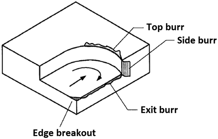
Face milling burrs. 21
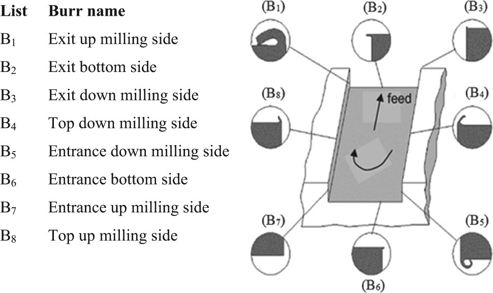
Slot milling burrs. 22
Factors governing milling burr formation
Burr formation is a crucial issue in industrial circles. Previous studies have shown that burr formation is almost impossible to avoid. 30 Related studies covering the following dimensions are of great interest:
Situations requiring burr size minimization;
Situations requiring regulation and standardization of burrs;
Situations requiring burr removal (deburring).
To examine these situations, it is necessary to examine burr formation behavior with respect to changes made in cutting conditions. Gillespie and Blotter 31 observed that burr formation cannot be avoided solely by changing the feed rate, the cutting speed and the tool geometry. According to Sofronas, 6 Aurich et al. 12 and Tseng and Chiou, 32 the following are the principal factors governing milling burr formation:
Machined part (geometry, dimension, mechanical properties, etc.);
Cutting parameters (cutting speed, feed rate, depth of cut, etc.);
Cutting tool (material, shape, geometry, rake angle, lead angle, helix angle, etc.);
Machine tool (rotational speed, dynamic strength, etc.);
Manufacturing strategy (tool path, coolant, back cutting, lubrication, minimum quantity lubrication (MQL), etc.);
Other parameters (e.g. cutting forces).
This summary is, however, still limited due to the complex interaction effects that exist between process parameters since their degree of influence on burr formation varies considerably simply by adding or removing cutting parameters and/or changing the material. In other words, factors governing burr formation cannot easily be classified as direct and indirect factors. 33
The following sections present the dominant process parameters influencing the milling burr formation mechanism and size.
Machined part (workpiece)
Machined part properties (e.g. chemical, mechanical properties) have significant effects on the burr formation process. The dominant mechanical properties usually reported in the literature are hardness, ductility, yield strength and elongation. 34 According to Aurich et al., 12 higher ductility materials tend to generate larger burrs, but limited, if not none, burr formation is anticipated when the material is restricted to deform in the force direction.
The most commonly used materials in aerospace industries are aluminum alloys, titanium alloys, nickel-based alloys and composite materials. Most of these materials are ductile, and generally speaking, ductility is one of the most important material properties. 34 According to Kim and Dornfeld, 35 the machining of ductile materials tends to form larger burrs, particularly at higher levels of cutting speed and feed rate. However, when the material is brittle, fractured burrs (negative burrs) are formed on the edge part. This phenomenon can be reinforced at higher cutting speeds and feed rates, creating irregular burrs. The metallographic characteristics of the machined part could influence burr formation, as the orientation of the machining direction could metallographically generate less distortion; consequently, less burr formation is expected. 35 The workpiece edge angle is the most prominent geometrical element of the workpiece that highly affects the burr formation mechanism. According to Przyklenk 36 and Wygowski, 37 cutting tests on the edge angle lower than 90° generate long and thin burrs, while short and thick burrs are formed on parts with edge angles of 90° or larger. According to Sofronas, 6 the burr size increases with an increase in the ratio of the chip and workpiece shear stress (τc/τw). The burr size is reduced when there is an increase in the shear stress of the part (τw) or a decrease in the shear stress of the chip (τc). The disadvantage of this method is that cracks might develop in hardened surface parts, causing difficulties in controlling the burr formation process. An increase in the temperature hardens most materials, and consequently affects the machining and deburring performance, even if the burrs created are small. According to Gillespie, 7 taking steps to prevent plastic deformation reduces the incidence of burr formation. His proposed methods include laser treatments, hard machining, localized mechanical processes and chemical and thermal treatments. In addition, chamfering on the external edges of the machined part before the cutting operation is an excellent approach to prevent material deformation at the part edge, and consequently achieve burr size reduction. 30
Cutting conditions
According to Avila and Dornfeld, 38 burr height varies irregularly with changing cutting conditions. Increasing the cutting speed leads to reduced burr size. In addition, milling operations at higher feed rates reduces the burr size, while creating secondary burrs that are easier to remove. From Rangarajan, 39 when the machined part surface is hardened in high-speed machining, a transition from ductile to brittle behavior may occur. This phenomenon may lead to decreased burr height. Chern 19 analyzed burr formation during the face milling of aluminum alloys. He found that secondary burr formation is dominated by the depth of cut and the feed rate. Nakayama and Arai 8 showed that the burr size can be reduced by limiting the undeformed chip thickness. The cutting conditions, tool and workpiece geometry may reduce the shear strain supported by the chip, therefore possibly leading to burr reduction. Kim and Dornfeld 35 showed that higher levels of the depth of cut generally increase the burr size. As discussed by Tseng and Chiou, 32 milling burrs are considered as Poisson burrs, which are not affected by cutting conditions. Wang and Zhang 40 indicated that an increase in the depth of cut, the feed rate, the cutting edge angle and the back rake angle leads to decreased burr height. Longer burrs in the cutting direction are formed when larger corner radii are used. According to Schäfer 41 and De Souza et al., 42 lower feed rate levels lead to a small burr size. Conversely, Kishimoto et al., 16 Wang and Zhang 40 and Jones and Furness 43 found that higher feed rate levels reduce the burr size. This shows that the outcomes of experimental studies are not always similar. Olvera and Barrow 44 found that the exit angle and the depth of cut influence the exit burr in the cutting direction, whereas the depth of cut is the main factor affecting the exit burr in the feed direction. According to Shefelbine and Dornfeld 45 and Olvera and Barrow, 46 the use of high levels of axial depth of cut (ap) increases the possibility of burr size minimization, but may also cause inevitable damage to the cutting tool, the machine and machined part functionality. Therefore, the use of very high and/or low cutting parameters levels is not suggested during milling operations. Tiabi 30 listed the order of the most influential cutting parameters, including the cutting speed, the feed per tooth, the depth of cut, material properties and the cutting tool on height of six type of burrs, the surface roughness and the cutting force (Table 1) during the slot milling of three aluminum alloys, namely, AA 7075-T6, AA 6601-T6 and AA 2024-T351.
Summary of effects of machining conditions on milling burr height when milling wrought aluminum alloys: the most significant cutting parameters are ranked 1 and the least are ranked 5.
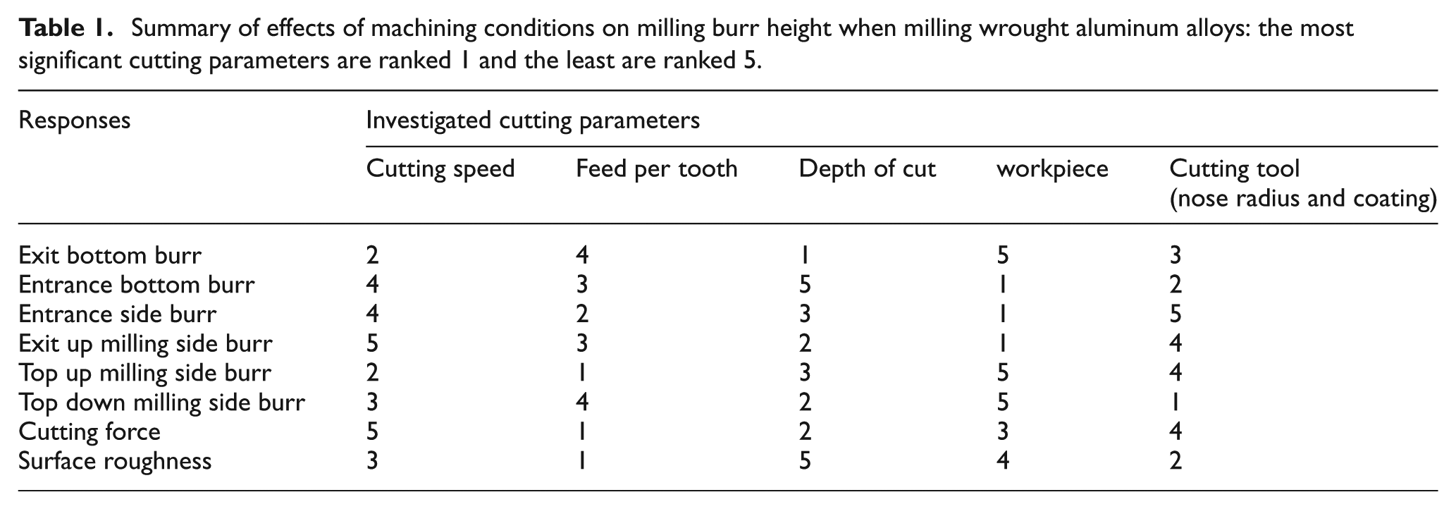
From Table 1, it could be inferred that the factors governing each machining response are not similar. The effects of cutting parameters on top, entrance and exit burr thickness and height (Figure 6) during the slot milling of AA 2024-T351 and AA 6061-T6 were statistically investigated by Niknam and Songmene.27,47 Among the investigated burrs, exit up milling thickness could be controlled by cutting process parameters (Figure 7) while other burrs, such as exit up milling burr height (Figure 8), are affected by the interactive effects between process parameters, but not by the direct effects of cutting parameters.
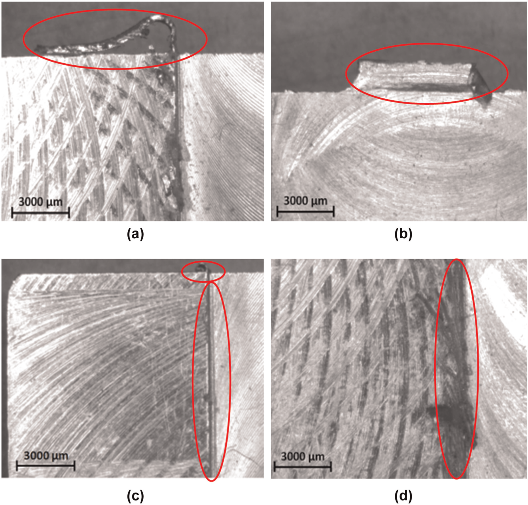
Investigated slot milling burrs: (a) exit up milling side burr, (b) exit bottom burr, (c) milling burrs along entrance and top down sides and (d) top up milling burr.
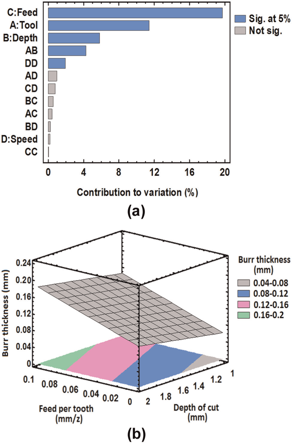
(a) Pareto chart and (b) 3D contour plot of exit up milling burr thickness. 28
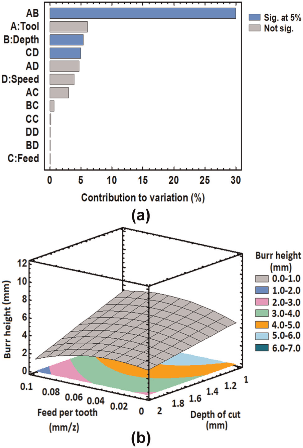
(a) Pareto chart and (b) 3D contour plot of exit up milling burr height. 28
Cutting tool geometry
Bansal 48 found that using milling inserts with positive axial rake and negative radial rake angles led to satisfactory burr size and surface quality. An increased axial rake angle and a decreased lead angle lead to smaller burrs, while a larger nose radius increases the incidence of burr formation. 12 According to Niknam and Songmene, 47 slot milling with a larger insert nose radius (Rε) leads to bigger exit bottom burr and smaller exit up milling side burr. In addition, when a larger Rε pretty close to the axial depth of cut is used, a primary exit bottom burr formation is expected. Consequently, a smaller exit up milling side burr is generated. Avila and Dornfeld 38 showed that tool geometry and in-plane exit angle Ψ have significant effects on burr size and edge breakout during the face milling of aluminum–silicon alloys (AlSi9Cu3 and AlSi7Mg). Tripathi and Dornfeld 49 reported the possibility of burr-free conditions when using diamond end mill tools at high cutting speeds. According to Gillespie and Blotter, 31 the use of sharp cutting edge tools with positive rake angle avoids built-up edge (BUE) formation, thus reducing the burr size. According to Olvera and Barrow, 46 tool coating has a negligible influence on face milling burrs. However, a certain level of coating influence on slot milling burrs was observed by Niknam and Songmene. 47 In a study reported by Jones and Furness, 43 milling with a 76°–118° exit angle generates a smaller exit burr, while Luo et al. 50 showed that the largest burrs were created in a 90° exit angle. This shows that addressing the optimum exit angle for burr size reduction in milling operations is not an easy task. According to Kim and Dornfeld, 35 De Souza et al., 42 Wang and Zhang, 51 the tool condition and cutting parameters used, in particular, the feed rate, are the main governing factors affecting burr formation.
As pointed out by De Souza et al., 42 tool wear increases the contact area of the burr–tool interface, and consequently, increases the cutting forces and stress distributions (Figure 9). Tool wear may physically occur on two sides of the cutting tool, mainly on the rake face and the flank face, thereby forming crater wear and flank wear. According to Choi et al., 52 tool wear highly affects the burr formation process when the tool enters and exits the machined part. Large entrance burrs formed when using worn tools resulted by different kinematic engagement rather than back cutting.
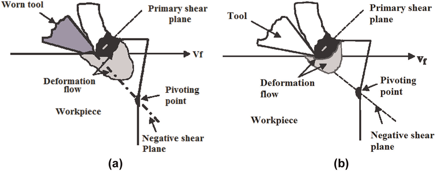
Shear angle and pivoting point for: (a) worn tool and (b) sharp tool.
According to Gillespie and Blotter, 31 Tseng and Chiou 32 and Kim and Dornfeld, 35 using higher cutting speeds and feed rates when cutting certain materials may increase the cutting temperature and consequently reduce the tool life as a result of tool wear. When the strain rate of the material increases, it effectively enlarges the burr dimension. A similar problem may occur when using dry machining or an inadequate tool geometry.
Machining strategy
According to Wang and Zhang 51 and Chu CH and Dornfeld, 53 correctly selecting the machining strategy has positive effects on the burr formation mechanism. The main machining strategies proposed to date include the following:
Optimization of the tool path planning, including the machining direction and the tool engagement angle;
Using inserts and backup materials;
Using modified cutting parameters;
Using coolant and lubrication.
Tsann-Rong 25 reported that the burr height (Bh) is strongly dependent on the milling process. According to Olvera and Barrow, 44 the exit angle and tool nose geometry significantly influence exit burr characteristics. Luo et al. 50 showed that the friction angle becomes larger with an increase in the exit angle and the oblique cutting angle. This results in longer exit burrs and exit up milling side burrs, respectively. To predict the burr size in face milling, several sets of algorithms were presented by Chu et al. 54 and Rangarajan et al. 55 and have led to a proposal of tool path planning approaches for burr size minimization. The effect of back cutting on burr formation was reported by Rangarajan and Dornfeld. 56 Przyklenk 36 proposed a new strategy for burr reduction by using dry ice snow to cool down the machined part edge. Shefelbine and Dornfeld45,57 stated that the use of coolant decreases the burr size, while larger burr is expected when using worn tools.
According to Tiabi, 30 proper lubrication reduces friction between the workpiece and the tool, and consequently, reduces the incidence of burr formation. However, as pointed out by Aurich et al., 58 in the case of certain materials, the use of lubricant hardens the burrs and complicates the deburring processes. Moreover, the use of cutting fluids seriously degrades the environmental air quality and increases machining costs by 16%–20%. One alternative approach with reduced cost and greater environmental benefits is dry machining. Many works22,27–29,59–63 on dry milling operation were reported in literature. According to Klocke and Eisenblätter, 64 the processes constitute a suitable candidate for the machining of ductile materials, such as aluminum alloys.
When dealing with hard-to-cut materials, it is recommended to apply a new technique consisting of just a few millimeters of fluid, known as the MQL, to the tool’s cutting edge. During MQL machining, the coolant or the lubricant is first atomized in a nozzle to form fine droplets and then fed to cutting zone in the form of an aerosol spray at a rate not exceeding 100 mL/h. 26 The major benefits of MQL in burr size minimization were reported by Rahman et al. 65 and De Lacalle et al. 66 However, further investigation is still required to select the suitable cutting conditions over a limited range of process parameters and materials studied.
Cutting forces
It is believed that the burr formation mechanism depends highly on the chip formation mechanism. 22 In milling operations, the chip thickness h(φ) varies periodically as a function of the time-varying immersion angle (φ). Cutting forces and chip thickness h(φ) are highly correlated as cutting forces are essentially affected by the feed rate, the depth of cut and the tool and workpiece geometry. Therefore, it could be inferred that milling burr formation is influenced by cutting forces. 30 The direction and intensity of cutting forces affect the volume of the chip generated and can also play an important role in material deformation. In the case of milling operations, cutting forces can be theoretically and computationally calculated.67,68 The influence of cutting forces on milling burr formation has been reported by Niknam and Songmene, 22 Zedan et al. 33 and Niknam et al. 69
Considering the work presented in this section on factors governing milling burr formation, it could be inferred that due to complex mechanisms of burr formation, direct and interactive effects between process parameters, a large number of experiments are required to evaluate the effects of process parameters on burr formation and size. In addition to massive non-desirable expenses, the dominant parameters of burr formation during oblique and orthogonal milling operations are still unknown. Therefore, the outcomes of experimental studies are not always consistent. For instance, Schäfer 41 and De Souza et al. 42 showed that a low feed rate reduces the burr size, while Kishimoto et al., 16 Wang and Zhang 40 and Jones and Furness 43 showed that increasing the feed rate reduces the burr size. This may be due to temperature effects, machine tool conditions, the stability of the cutting process and material properties. In addition, when dealing with dry high-speed milling, except for few works,22,57,61–64 only limited studies have considered the effects of dry high-speed machining on milling burr formation, particularly on slot milling burrs.
The proper selection of cutting parameters by means of burr size minimization becomes more complicated when cutting tools with various end nose radii (Rε) and coatings are used. The combination of statistical and experimental approaches is a good approach to better understand the burr formation mechanism and to define the factors governing milling burrs. Furthermore, knowing that the best setting levels of process parameters needed to minimize each response are not similar, the question is how to obtain the best setting levels of process parameters to reach the optimum or near-optimum burr size. This issue becomes more complex as for a given machined part, cutting parameter optimization for burr size minimization alone may frequently deteriorate other machining performances, such as tool life and surface roughness. Therefore, the use of optimization methods for the correct selection of process parameters is strongly recommended. 70
According to Niknam et al., 28 achieving better surface finish and acceptable burr size at the same time is possible when using optimization tools such as the desirability function. In this work, 28 the desirability function, Di(x), was used to introduce an overall criterion of desirability of proposed input setting parameters. The adequacy of the proposed process setting levels was verified by a desirability of Di = 0.951 (Figure 10). It was found that the feed per tooth and the tool (geometry and coating) have the most significant effects on the simultaneous minimization of milling burr size and surface roughness, while the depth of cut and the cutting speed have a relatively less significant effect on Di(x). As shown in Figure 13, when using a lower level of the depth of cut (1 mm) and the feed per tooth (0.01 mm/z), the (Di)max = 0.951 is achieved. In this work, a coated end milling cutting tool with a diameter (D) of 19.05 mm was used with various insert nose radius (Rε) and coating levels. Other cutting parameters used were an end milling tool with three flutes (Z = 3), an insert nose radius (Rε) of 0.83 mm and a TiAlN coating and tool diameter (D) of 19.05 mm. With this cutting condition, the optimum burr height (Bh), burr thickness (Bt) and surface roughness (Ra) values were 0.1398 mm, 0.034 mm and 0.169 µm, respectively.
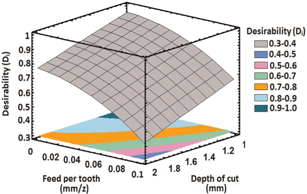
3D contour plot of Di at optimum cutting condition. 28
Further works on the optimization of milling parameters to optimize machining responses have been reported,71–73 but none of them specifically focuses on slot milling burrs.
Milling burr formation modeling
Burr formation modeling has been carried using various research methods such as experimental studies and analytical and numerical modeling. Considering the complexity of milling burr formation process, 2D models are typically used more frequently. Numerous burr expert systems have been developed on the basis of experimental studies. These systems are database prediction tools 34 that involve comprehensive experimentation by varying process parameters to monitor burr formation patterns. They have been successfully implemented in many cases, especially when only a few parameters need to be varied (e.g. the drilling process). However, providing a database for all elaborated parameters in milling operations is a time-consuming and costly approach. 48
The major research works covering experimental studies and analytical and numerical milling burr formation models are presented in the following subsections.
Analytical modeling
Among machining operations, analytical modeling of milling burr formation is quite challenging. This is due to the complexity of the milling burr formation mechanism, in which burrs are created when the cutter enters and exits the machined part. Therefore, the base model for studying the burr formation process has been the orthogonal cutting scheme. 74 The first milling burr formation model was proposed by Gillespie. 13 Olvera and Barrow 44 developed a burr size prediction model for various exit angles and nose geometries. The slip line method was also used to model exit burr formation in orthogonal cutting. 34 The analytical modeling of the burr formation process was also extensively studied by Professor D. Dornfeld and his associates at the University of California, Berkeley. Ko and Dornfeld 18 proposed a burr formation model in orthogonal cutting with a three-stage burr formation process, including burrs initiation, burr development and final burr formation. Later, Narayanaswami and Dornfeld 15 proposed a tool entrance/exit model. Chern and Dornfeld 9 proposed a burr formation/breakout model for orthogonal cutting, indicating the direct effects of plastic bending and shearing of negative deformation on burr formation.
An analytical model of material exhibiting fracture during burr formation was proposed by Ko and Dornfeld, 75 which used the fracture strain from McClintock’s ductile fracture criterion. The burr size estimations were found to be accurate for less ductile materials (i.e. Al 6061-T6 and Al 2024-T4), while the results of ductile materials (i.e. copper and aluminum alloy) were not consistent. A transition from primary to secondary burrs with respect to tool engagement was shown by Hashimura et al. 10 This led to the development of a burr size prediction system, known as the exit order sequence (EOS). This method is mainly used for the face milling process. 76 A few other recent works have focused on burr formation modeling in micro-end milling operations,77,78 paying particular attention to the chip size effect on burr formation. Based on the existing research works reported to date, Niknam and Songmene 22 presented a burr size model in slot milling. In their work, 22 as similar as the method proposed by Ko and Dornfeld, 18 certain levels of assumptions were used and the burr formation mechanism in ductile materials was divided into three parts, namely, initiation, development and burr formation. The burr formation in the exit zone was thus modeled as an orthogonal process, and consequently, the effects of the plunge depth, cutter geometry and cutting speed were ignored. In order to consider the tool rotation angle and non-uniform chip thickness on the burr formation process, a set of mathematical operations were applied on milling burr formation at the end of a cut. By considering only a small advancement of the tool at the transition from chip formation to burr formation, according to the principles of the energy conservation theory, the work done for chip formation was assumed to be equal to that carried out for burr formation. Extending the theory, the mathematical model for burr thickness (Bt) estimation in exit up milling side burr was proposed (see equation (1))
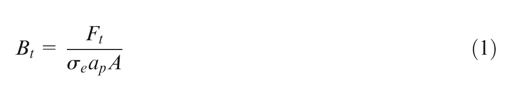
where Ft is the tangential cutting force, Bt is the burr thickness, σe is the yield strength of the machined part, A is a constant value as a function of negative shear angle (β0) and ap is the axial depth of cut.
It is evident that the only unknown parameter in equation (1) is Ft. In order to calculate the Bt and validate the model presented in equation (1), the Ft can either be measured experimentally or estimated computationally. The presented model was later modified and the computational modeling approach also established (see equation 2)
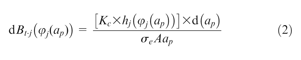
where Kc is the specific cutting force coefficient, φ is the immersion angle, hj(φj) is the variable chip thickness at immersion angle (φ) in flute j and dBt,j(φj(ap)) is the differential burr thickness with respect to the immersion angle (φ) in flute j.
The models presented by Niknam and Songmene 22 were experimentally verified (Figure 11). Both analytical and computational burr thickness models do not require experimental measurements of the shear angle (φ), the friction angle (λ) and the tool–chip contact length (L) for burr size measurement. As mentioned earlier, milling burr size prediction is extremely challenging due to the effects of factors that are very difficult to model explicitly. Through the works presented, a number of simplifying assumptions, including orthogonal cutting, which ignores the flute geometry and the yield stress that were assumed to be constant for all conditions, were used. Furthermore, micro-structural effects, such as grain size and boundary effects, were all ignored. Errors related to the effects of specific cutting pressures and the coated tool on burr formation were also neglected.
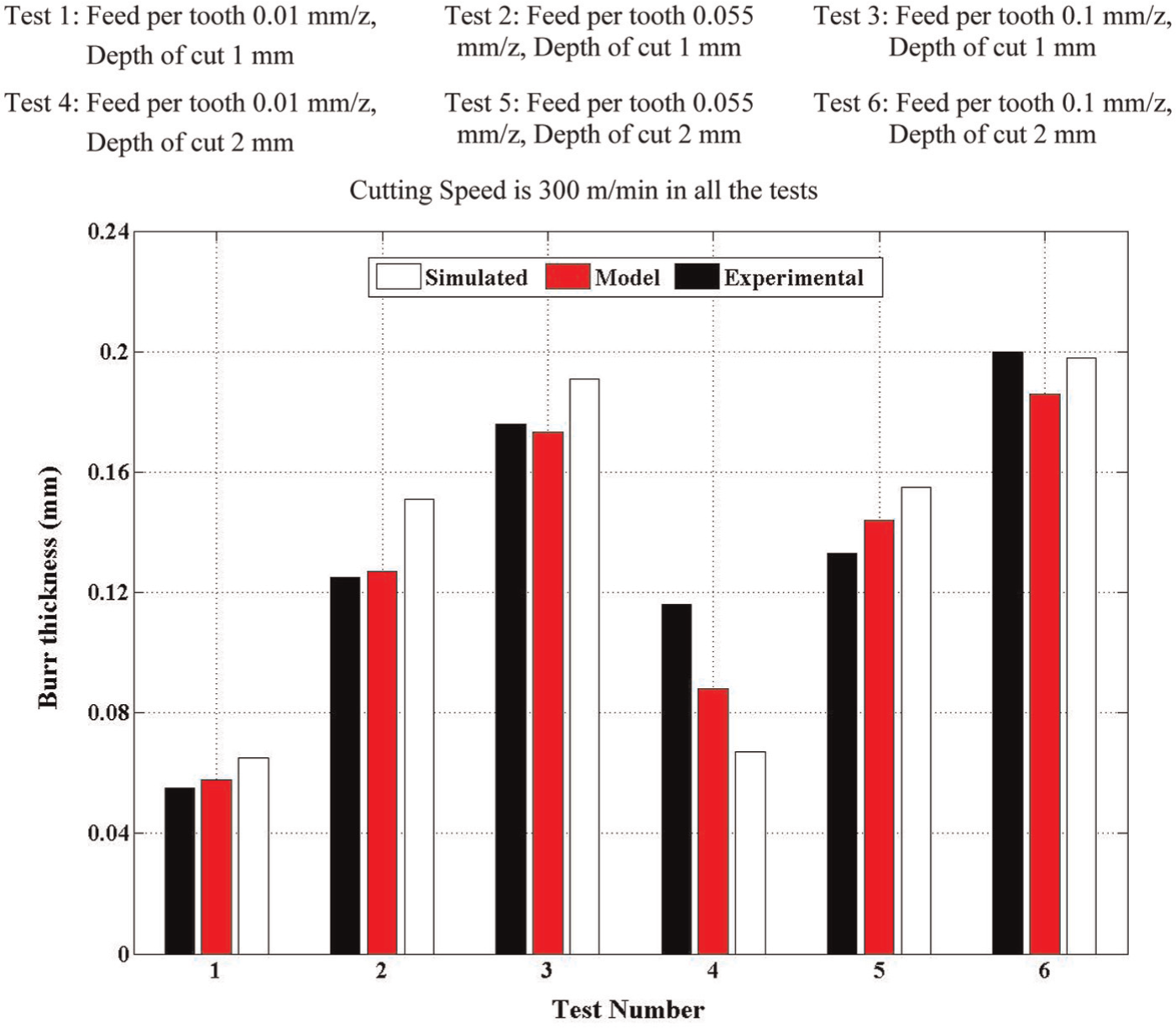
Experimental verification of analytical model (using equation (1)) and simulated model (using equation (2)).
Experimental study/modeling
Kishimoto et al. 16 studied face milling burr formation with a special focus on primary and secondary burr formations. The effects of the tool geometry, various workpiece materials, cutting parameters and the tool path were investigated by Gillespie. 13 Tsann-Rong 25 reported experimental results on burr formation and tool chipping during the face milling of stainless steel, when using a fly milling cutter in single-tooth face milling tests. Milling burr formation was predicted and minimized for slot and face milling processes using tool path planning strategies and process parameter optimization, as well as workpiece rigidity strengthening. 23 Burr formation during the orthogonal cutting of aluminum alloy was studied by Hashimura and Dornfeld. 79 Higher feed rates lead to thicker burr formation as a result of an increased tool position relative to the pivot point.
The influences of tool wear, cutting speed and coolant on burr size during the face milling of cast iron and aluminum alloys were investigated by Shefelbine and Dornfeld.45,57 Various tool materials and tool wear conditions were observed in face milling gray cast iron. 80 Olvera and Barrow 46 studied the face milling of medium carbon steel AISI 1040. Chern 81 reported the influence of cutting conditions on burr formation when fly milling cutters were used in the single-tooth face milling of aluminum alloys. He reported that the burr geometry is strongly dependent on the in-plane exit angle. According to Avila and Dornfeld, 38 burr height irregularly varies with changes in cutting conditions. Biermann and Heilmann 82 investigated the relationship between burr formation and notch wear. They also presented burr reduction strategies for the turning, drilling and milling of different materials. In addition, a new promising strategy for milling burr reduction was proposed, involving the cooling of the component edge with dry ice snow. 82 According to Wang and Zhang, 51 the dominant process parameters in cutting direction burrs are cutting parameters, the shape of the workpiece end, the cutting tool geometry and the workpiece properties.
Tripathi and Dornfeld 49 presented a review of various methodologies for burr prediction and minimization in face milling, paying particular attention to the geometric solutions employed, namely, understanding and modification of tool engagement conditions. Burr formation in the face milling of AZ91HP magnesium alloy was investigated by Matuszak and Zaleski. 83 The effects of the cutting speed, the feed rate, material hardness, tool wear and the cutting tool exit angle on burr formation during face milling of aluminum alloy were reported by Jones and Furness. 43 In metal cutting, cutting tests with exit angles of 76°–118° led to smaller burrs. Furthermore, higher feed rates, lower cutting speeds, new cutting tools and harder materials have positive effects on burr size minimization.
De Souza et al. 42 used two face milling tools, both coated with polycrystalline cubic boron nitride (PCBN), to study burr formation in the high-speed machining of gray cast iron under various cutting conditions. The influence of the exit angle and the tool nose geometry on exit burr formation for both finishing and roughing conditions (small and large depth of cut) was reported by Olvera and Barrow. 44 The results show that four different types of burrs can be created on the exit edge (tear, curly, rubbing and wavy burrs), burrs that are substantially influenced by the exit angle and the tool nose geometry. Luo et al. 50 studied the mechanism of feed direction burrs in the slot milling of aluminum alloys. According to Rahman et al., 65 a lower burr height was observed when using MQL. Additionally, with MQL, no chips stick to the tool, unlike milling tests under flood cooling and dry conditions. As stated by De Lacalle et al., 66 MQL systems are very useful for chip evacuation and manufacturing cost reduction.
Numerous process parameters on face milling burrs were reported in various studies.10,16,19,25,38,44,46,84,85 Most of the existing research works in the literature characterize the burr height, while from a deburring perspective, the burr thickness is of interest because it describes the time and method necessary for deburring a workpiece, 42 In addition, only few studies have determined the dominant process parameters on burr size.27–29,47,86
To the best of the authors’ knowledge, surprisingly except few works,27,47,50,87,88 very limited information is available on dominant process parameters for slot milling burr formation. Among these, Niknam and Songmene27,47 presented an overview of the factors governing the size (thickness and height) of large and visible burrs (see Figure 7) during the slot milling of aluminum alloys. Among investigated burrs, exit up milling side burr thickness is significantly affected by variation in machining parameters. Furthermore, it has a strong correlation with tangential force (Ft). Linear first-order mathematical models were developed to predict exit up milling side burr thickness and Ft as a function of the feed per tooth and the depth of cut. 27 It was also found that the dominant cutting parameters on each burr are different. In addition, no relationship could be formulated between burr thickness and height. 47
Numerical methods
Finite element method
Among many numerical methods, finite element method (FEM) has drawn particular attention for metal cutting simulation. FEM was first introduced in the 1960s and has been widely used to analyze the tool design and forming processes. 89 When using FEM, it becomes possible to investigate the effects of process parameters (see Figure 12) on responses that are not measurable or extremely difficult to measure; these include contact stresses on the rake face and flank face of the tool, cutting temperature at the tool–chip and tool–workpiece interfaces, chip temperature field and sliding velocities between the chip and the tool. Having adequate knowledge of these process parameters provides a better understanding of cutting physics and may enable us to simulate the cutting forces, tool temperature, stresses, chip formation and burr formation. 89 An extensive overview of reported works that used FEM to model burr formation will be presented below.
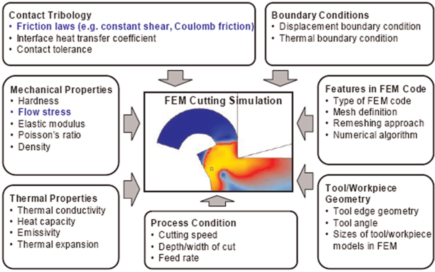
Major process parameters for FEM simulation of metal cutting. 89
FEM applications in milling burr formation modeling
The main aim of numerical analysis (e.g. simulation) of burr formation is burr minimization. 34 By introducing new models of material behavior under high strain rates, many aspects of FE models of metal cutting, including burr formation models, have been tuned to more realistic levels. 19 Burr formation modeling using FEM was initiated by Park. 90 The FE code ABAQUS/Explicit was used, and the tool and the workpiece were, respectively, assumed to be rigid and plastic. However, the use of a sharp cutting tool and the element-separation criterion was assumed in this work. Park 91 subsequently used FEM to determine the effects of the exit angle, the rake angle and backup materials on burr formation processes. Hashimura et al. 10 developed a basic burr formation model, which includes the effect of material properties in orthogonal cutting. The experimental verifications were confirmed when an FEM simulation-based elastic–plastic model was used.
A series of FEM simulations were performed to model the friction along the tool–chip interface and the interior of the cutting tool. 34 It was found that the chip–tool contact length is influenced by the friction coefficient, and that the chip geometry is also influenced by friction. According to Regel et al., 92 a region of high negative hydrostatic pressure was observed in the transition from steady-state cutting operation to burr formation. To date, the exact effects of hydrostatic pressure on burr formation remain unknown. Chu et al. 54 proposed a milling burr predicting system using a burr control chart (burr predicting system). Klocke et al. 93 presented 2D FE burr formation models in orthogonal cutting using implicit Lagrangian codes. Klocke et al. 93 found that an expressive knowledge of stress distribution, strain, strain rate and temperature variations can be obtained using FE modeling of burr formation. However, part of the simulation results obtained did not properly correspond with the experimental results. The modeled burr size (thickness and height) were different from those measured experimentally. This was related to the chip formation mechanism, which largely influences experimental and modeling results. One of the crucial inputs for FE simulation of high-speed machining processes is the availability of material plastic properties under that specific machining condition (i.e. flow stress as a function of strain, strain rate and temperature). Because of the wide range of limitations imposed, except for a few reported works,94–96 three-dimensional (3D) FE milling burr formation models are rarely available. 34 As described earlier, one of the main criticisms leveled against FEM is that the results obtained depend on the accuracy of input boundary conditions, which are not yet advanced and, therefore, are usually used in simplified form. Existing FE burr formation models in turning, drilling and non-traditional machining operations are listed in Aurich et al. 12
Milling burr formation control
A good understanding of the burr formation mechanism leads to better prevention and minimization of burr formation. The effective factors in this regard are proper knowledge on tool–workpiece intersections, analytical burr formation models and databases describing burr formation for optimal edge quality.
As described in the preceding sections, tool path planning and control, including machining direction and the tool engagement angle, are deemed to constitute one of the main machining strategies proposed so far that has been successfully applied for burr size minimization in milling. The major works on proposed tool path planning algorithms for tool exit avoidance from the machined part, and consequently burr size minimization, are presented in the following sections.
Tool path planning
Previous studies have shown that machining edge defects, including burr formation, can be reduced when the cutting tool is prevented from exiting the work part while the material is removed or exiting only under carefully described conditions. 53 This could be achieved by controlling tool engagement conditions (Figure 13). The main factors affecting these conditions are the workpiece geometry, the tool geometry and tool path. Considering that the workpiece design and the tool geometry are usually uniform, more attention should be paid to burr size minimization by avoiding tool exit or limiting the in-plane exit angle. 12 Niknam et al. 21 presented and analyzed six tool path strategies for burr formation control in slot milling.
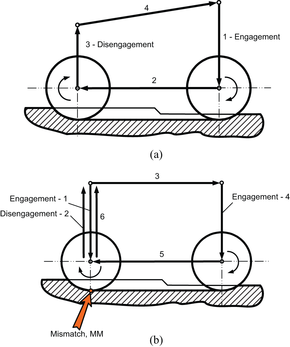
Example of tool engagement paths proposed by Niknam et al.: 21 (a) traditional tool path approach and (b) double engagement tool path.
Aurich et al. 12 proposed five geometrical approaches for tool path planning as follows:
Window framing approach or contour parallel;
Exit free tool path;
Feature property;
Feasible region approach;
Continuity in tool path.
The first two approaches will be presented in this article. For more information on this subject, readers are referred to Aurich et al. 12 and Niknam et al. 21
Window framing approach or contour parallel
This approach is suggested as a burr size minimization solution, which could be implemented by adjusting the workpiece orientation to minimize the primary burrs.97,98 The application of this method was expanded by Chu and Dornfeld 99 to multiple tool paths and work parts with curved edges and inner profiles. Exit burr size minimization could be achieved by selecting the tool feed directions and simulating the primary burr locations.
Exit free tool path
Chu and Dornfeld 100 developed two approaches for the tool path planning of 2D polygons. Rangarajan et al. 55 generated an exit burr tool path globally by offsetting the workpiece edges with the appropriate widths of cut. As a drawback, using this approach increases the machining time. In addition, a zigzag tool path must also be applied to remove the remaining materials.
Future trends
Through growing demands on part quality, functional performance and global competition, special attention has been paid to burr formation which appears to be one of the major troublesome impediments to part quality, high productivity and automation.
Considering that the burr formation phenomenon is inevitable, particular attention should be paid to burr control rather than burr avoidance. The following strategies are recommended for burr minimization and prevention and for improving the knowledge on burr and deburring:
An expansion of experimental works to cover more materials, cutting parameters and tool geometries in order to discover the effects of other parameters on the burr size (e.g. energy level, lubrication mode), using theoretical and/or experimental studies followed by statistical approaches could be targeted.
Development of 3D simulation of milling burr formation models, coupled with advanced cutting force and temperature modeling algorithms, capable of indicating the interaction and dependencies of factors governing burr formation.
Development of burr size estimation systems using specialized sensors. To this end, the sensitivity of industrial sensors to a broad range of cutting parameters should be examined. The ultimate goal is to develop an automated online burr size monitoring system.
The key points as already pointed out by Aurich et al. 12 remain to date. They include the following: (1) development of databases for adequate selection of optimal cutting conditions, (2) developing link between the burr size and deburring difficulty and (3) improving and automating burr detection and characterization strategies
Conclusion
In this article, machining burr classifications and formation mechanisms were presented. Furthermore, the milling burr formation mechanism, modeling approaches and factors governing burr size were described.
This work has led us to conclude that
There is a substantial need to reduce, prevent and eliminate burrs. The main benefit would be to reduce the needs of deburring operations. However, using deburring operations in some cases is still mandatory.
Burr formation modeling is a good approach for burr size minimization. There is no general burr formation model that can be used for all machining operations. Thus, more attention should be paid to understanding, controlling and optimizing milling burrs. Most of the existing research works in the literature aim to measure and/or predict the burr height. However, burr thickness is a critical parameter for selecting a desirable deburring technique.
In spite of the fact that numerous experimental works on burr formation exist, only a few studies have focused on the influence of the cutting tool (geometry and coating) and dry high-speed machining on milling burr formation in oblique and orthogonal cutting. It has been shown that the dominant cutting parameters on milling burr formation, size and location are still unclear. Therefore, extensive investigations are required in order to uncover the factors governing milling burr formation to acquire adequate knowledge regarding burr size minimization. This knowledge gap can be remedied by expanding the scope of the experimental works, and consequently, developing databases and design roles for the adequate selection of cutting parameters to optimize the burr size, the edge quality and the surface finish of work parts.
Analytical, experimental and numerical studies are among the approaches used for burr formation modeling. Developing analytical solutions for burr size modeling in general elastic–plastic problems with large deformation, such as milling operation, is a complicated task. Therefore, very limited analytical models have been reported for milling burr size prediction. Most of the available analytical models were constructed based on shear angle and tool–chip contact length, which are difficult to measure experimentally. Furthermore, limited information is available on the analytical modeling of slot milling burrs.
FEM is the most prominent numerical method for burr formation modeling. The accuracy of FEM results depends on the accuracy of applied input boundary conditions, which are usually used in simplified form. In addition, results are strongly influenced by the software used and more often experimental data are usually required for model construction.
Footnotes
Acknowledgements
The authors acknowledge the granted publication permissions by John Wiley & Sons, Inc. and American Society of Mechanical Engineers (ASME).
Declaration of conflicting interests
The authors declare that there is no conflict of interest.
Funding
The authors would like to thank the National Sciences and Engineering Research Council of Canada (NSERC) and the Consortium for Research and Innovation in Aerospace in Quebec (CRIAQ) for their financial supports. Partial financial support from the Fonds Québécois de la Recherche sur la Nature et les Technologies (FQRNT) by the intermediary of the Aluminum Research Centre—REGAL is gratefully acknowledged.