
Abstract
Additive manufacturing is proposed as a novel alternative to coin blank’s production routes based on rolling, blanking and edge rimming. The presentation draws from laser powder bed fusion of cylinders, slicing into individual coin blanks by electro discharge machining and surface preparation by polishing, to coin minting in a laboratory press-tool system. Special emphasis is given to material deposition and coin minting due to the originality of producing coin blanks with complex intricate contoured holes and to the necessity of subjecting the additive manufactured coin blanks to extreme compressive stresses that are typical of coin minting. Numerical and experimental results confirm the excellent performance of the additive manufactured coin blanks. The new design layouts included in the additive manufactured coin blanks open the way to produce high value-added singular collector coins, which are disruptively different from those available in the market nowadays.
Introduction
Coin minting is an old metal forming process dating back to the time when dies were hand made by artisans known as engravers. The first industrial revolution and the development of the first steam-power coining presses open the way for the establishment of modern mints and to mass production of coins made from non-precious metals. Mass produced coins, commonly designated as circulating coins, are distinguished from collector coins (brilliant uncirculated and proof coins) because they have lower levels of sharpness, detail and finishing. Proof coins have the highest quality requirements and are high value-added collectables produced in relatively small batches.
Globalisation opened the possibility for mints to trade collector coins around the world instead of being mainly restricted to providing currency for national central banks. However, this new business opportunity came with the challenge of mints being able to present innovative and technologically bold products. This explains the reason why mints are nowadays strongly committed to the development of innovative collector coins with complex shapes and/or alternative new materials. 1
Under these circumstances, the main purpose of this paper is to give a step forward in the production of collector coins by proposing a new hybrid manufacturing approach that combines additive manufacturing by powder bed fusion with metal forming. Built cylinders with complex intricate contoured holes that are difficult or even impossible to manufacture by means of blanking, laser cutting or water jet are deposited by powder bed fusion and subsequently sliced and prepared into individual coin blanks (hereafter also designated as ‘blanks’, Figure 1(a)) by means of wire electro discharged machining (wire-EDM) and polishing. The additive manufactured blanks are then plastically formed into collector coins using press-tool systems similar to those utilised with commercial coin blanks. The new hybrid manufacturing route is schematically illustrated in Figure 1(b).
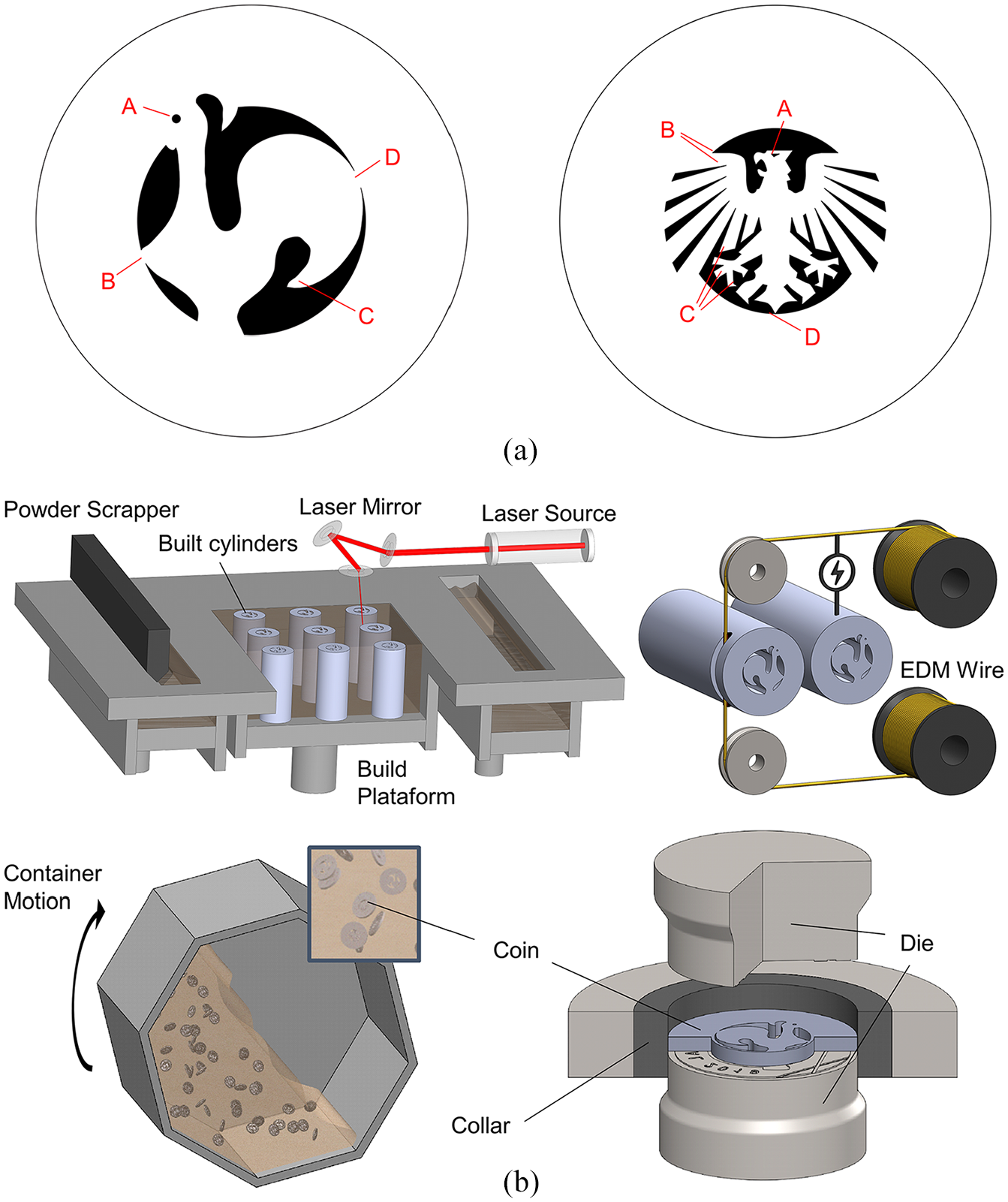
Fabrication of collector coins by combination of additive manufacturing and forming: (a) the two coin designs (‘Rooster’ and ‘Eagle’) with contoured holes (black regions) that were utilised in the investigation. Appropriate references to ‘A’, ‘B’, ‘C’ and ‘D’ details will be made later in the presentation (refer to Section 2) and (b) schematic representation of the new hybrid manufacturing route combining deposition by powder bed fusion, wire electro discharge machining, polishing and coin minting.
The idea of integrating additive manufacturing and metal forming is not new and has been around since the mid 2010’s. Main applications are concerned with material deposition to change the shape and improve the strength and wear resistance of metal formed parts. Examples include material deposition on parts fabricated by incremental forming, 2 deep drawing 3 and bending, 4 among others. One of these pioneering concepts due Hölker et al. 2 proposes a deeper level of integration in which metal forming, additive manufacturing and surface finishing are carried out in the same machine.
With regard to the inverse approach of using additive manufacturing to fabricate preforms for subsequent metal forming operations, as the authors are suggesting for coin minting, little information is available because the topic has only recently begun to be investigated. Deposition and forming of stiffness reinforcements in metal parts, 5 joining by forming of sheets and profiles using additive manufactured tenons,6,7 flow forming of additive manufactured tubes, 8 forging of additive manufactured preforms9–11 and incremental forming of additive manufactured sheets or thin-walled structures12,13 are among the pioneering applications in the field.
The integration of additive manufacturing and metal forming processes may also be analysed by its potential of fostering collaboration in distributed manufacturing networks 14 and changing into sustainable manufacturing, 15 but these two topics are out of the scope of this paper. In fact, and as mentioned before, the main contribution of this paper stems from the development and application of a new manufacturing route combining additive manufacturing and forming to fabricate collector coins.
The potential of using additive manufacturing as an alternative to conventional rolling, blanking and edge rimming, is expected to stimulate innovation in design by allowing the inclusion of complex intricate contoured holes in coin blanks. Blanks produced by additive manufacturing make it possible to produce high value-added singular collector coins, which are disruptively different from available coins with simple circular holes.
There are several reasons for including a forming (coin minting) operation in the overall manufacturing route instead of simply producing individual collector coins by additive manufacturing without resorting to secondary operations. Firstly, the difficulty of producing the reliefs of the individual obverse coin surfaces without introducing a significant number of structural supports. Secondly, a matter of productivity, because it is faster and more efficient to build a cylinder by additive manufacturing and slice it into individual coin blanks than to build one coin blank at a time. Thirdly, the quality requirements in terms of sharpness, detail and finishing that are only capable of being fulfilled by including polishing and coin minting operations in the overall manufacturing route. And finally, the possibility of coin minting being also used to incorporate security features in collector coins, when needed.
The presentation of the work performed by the authors is structured as follows. The next section presents the materials and methods utilised in process development and experimental testing. The section ‘Numerical Simulation’ introduces the finite element formulation and the computer implementation specifics utilised in the numerical modelling of coin minting. The section ‘Results and Discussion’ validates the overall manufacturing route by presenting and discussing the numerical and experimental results that were obtained from coin minting of additive manufactured blanks. The last section of the paper addresses the main conclusions.
Material and methods
Flow stress of the deposited material
The prototype collector coins were produced in AISI 316L stainless steel powder supplied by LPW Technology. Material deposition was carried out using laser powder bed fusion of metals (hereafter designated as ‘selective laser melting – SLM’) in a DMG Mori Lasertec 30SLM 2nd Gen. machine equipped with a 600 W laser.
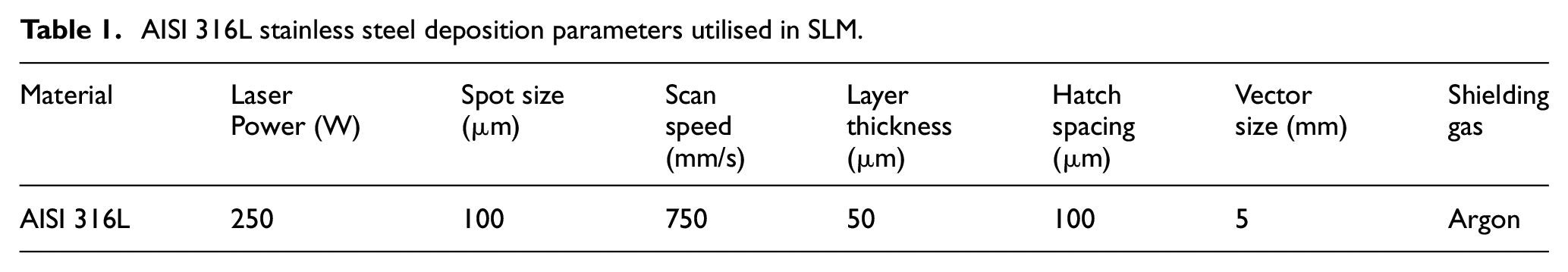
The true stress versus true strain curve of the material was determined by means of compression tests in specimens with 10 mm diameter and 15 mm height that were machined out of cylinders built-up by depositing material on a platform along the z-axis (Figure 2). A deposition strategy involving sectorial scanning with a maximum section length of 5 mm was utilised. The scan vectors are parallel bi-directional and are rotated by 63.5° between layers to avoid repeating the scan vector orientation until several layers are added. 16 The main parameters utilised in material deposition are summarised in Table 1.
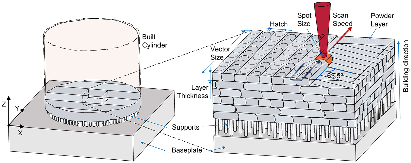
Schematic representation of the deposition strategy and parameters used in SLM for the fabrication of cylinders along the z axis.
AISI 316L stainless steel deposition parameters utilised in SLM.
The compression specimens were taken from the built-up cylinders along three different directions (x, y and z) and tests were carried out at room temperature on a hydraulic testing machine with a cross-head speed equal to 10 mm/min and the resulting flow stresses are included in Figure 3. Differences provided by specimens taken from the built-up cylinders along three different directions are negligible.
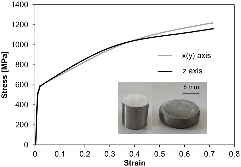
True stress – true strain curves of deposited AISI 316L stainless steel obtained from compression tests in specimens taken from cylinders built-up along the z and x(y) directions.
Fabrication of coin blanks and coin minting
Two prototype coin designs (‘Rooster’ and ‘Eagle’) were utilised to demonstrate the combination of additive manufacture and forming to fabricate collector coins. A closer look at Figure 1(a) allows understanding the main design layout features that make these prototype collector coins different from those available on the market. Firstly, the eyes of the ‘Rooster’ and ‘Eagle’ consist of very small holes – a circle with 0.8 mm of diameter and a triangle with approximately 0.4 mm of side, respectively (refer to ‘A’ in Figure 1(a)). Secondly, there are complex intricate contoured holes having tears with very small angles (refer to ‘B’ in Figure 1(a)). Thirdly, there are overhang corners that are not connected to the remaining geometry of the coin blanks (refer to ‘C’ in Figure 1(a)). And fourthly, there are very small bridges between the centre and outer region of the coin blanks (refer to ‘D’ in Figure 1(a)).
The cylinders from which the coin blanks were obtained had 60 mm height and were built by SLM along the z-axis in order to minimise the use of support structures and to improve the overall efficiency and quality of material deposition. In fact, building along other than the z-axis would increase the use of support structures and inhibit the fabrication of very small holes like those used in the eyes of the ‘Rooster’ and ‘Eagle’.
Wire electro-discharge machining and surface polishing were subsequently utilised to slice the cylinders into individual coin blanks with appropriate quality requirements. The holes were not polished although they could have been by subjecting the built-up cylinders to abrasive flow machining.
Figure 4 shows a scheme of the deposition strategy (refer to ‘1’, ‘2’, etc…) together with photographs after SLM, wire-EDM and polishing, in which the improvement of surface finishing is easily observed. Deposition parameters used in the fabrication of coin blanks by SLM were identical to those provided in Table 1.
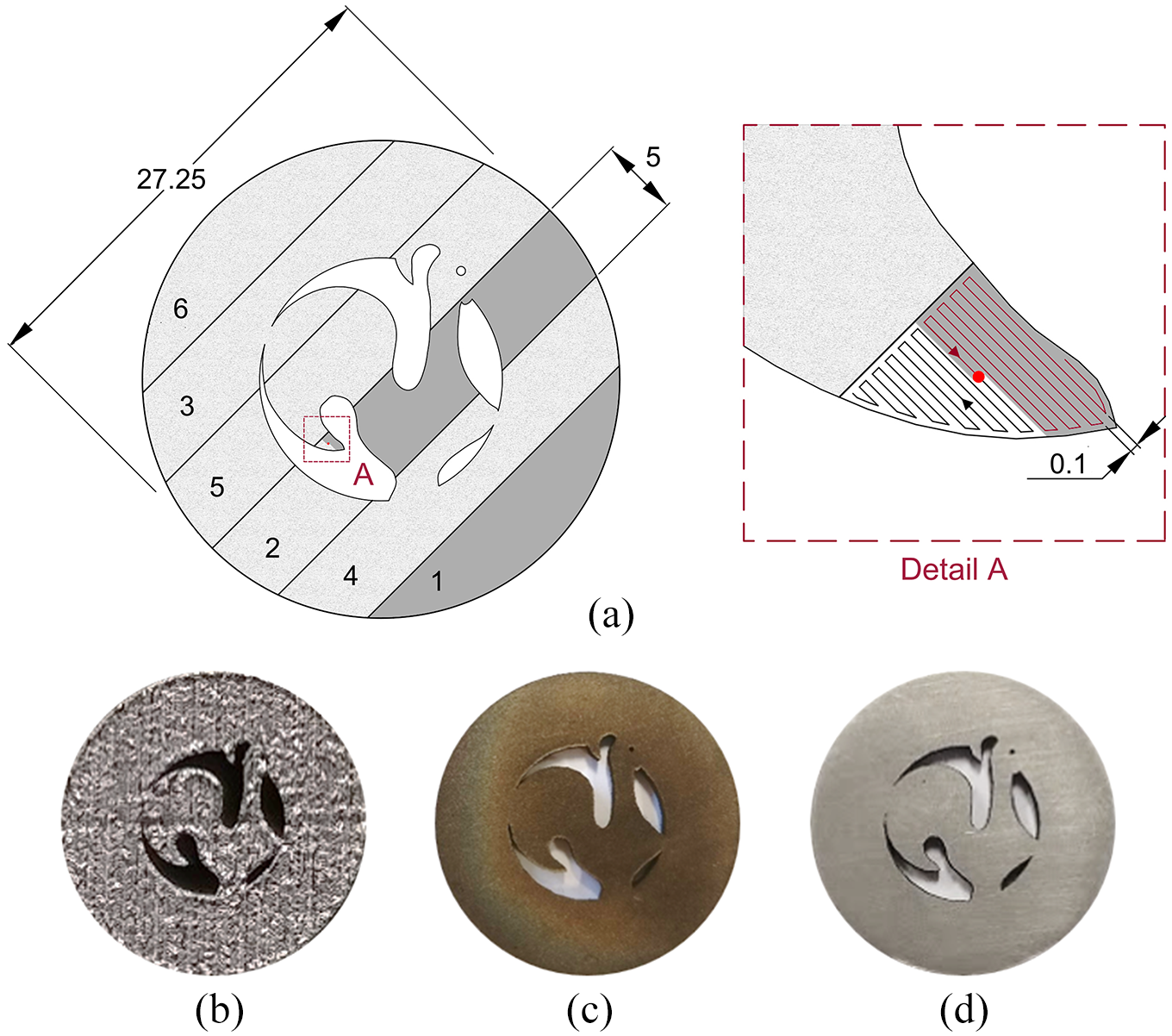
Cylinders built by SLM along the z-axis: (a) the deposition strategy for the ‘Rooster’ built cylinder, (b) photograph of the built cylinder’s end, (c) photograph of the coin blank surface after wire-EDM, (d) photograph of the coin blank surface after polishing.
The coin blanks were then compressed (coin minting) between dies in a press-tool (Figure 5) to impart lettering and other reliefs on both surfaces. The tool was designed and fabricated by the authors and consists of a simple laboratory system with an upper drive plate, a lower fixed plate, an upper die holder, a pair of reverse and obverse dies and a collar with an inner flat surface (Figure 5(a)). The dies have a central recess of 0.15 mm to avoid contact in these regions of the ‘Rooster’ and ‘Eagle’ coins (refer to the central blue area in the reverse and obverse die surfaces of Figure 5(b)). They were made from an AISI D3 cold work steel, also designated as DIN 1.2080, which was heat treated (hardening and tempering) to ensure a hardness of 60 HRc. The collar was made of tungsten carbide.
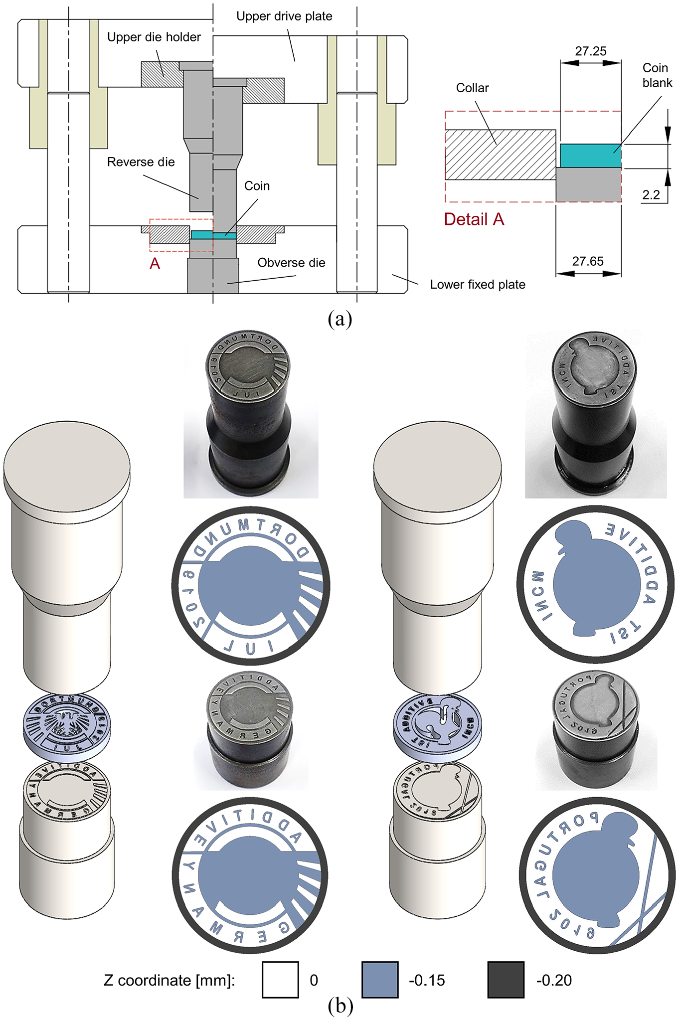
Laboratory press-tool system utilised in coin minting of additive manufactured coin blanks: (a) scheme of the press-tool system with the geometry of the coin blanks and (b) detail and photograph of the dies utilised in coin minting (‘Eagle’ and ‘Rooster’).
The coin minting experiments were carried out in the same hydraulic testing machine in which material compression tests were performed. In each test, the coin blanks were compressed up to the required end of stroke in order to replicate coin minting by a single strike. At least five repetitions were made for each prototype coin design.
Assessment of porosity
The overall level of porosity of the coin blanks and of the prototype coins after minting was determined by measuring their densities in a laboratory precision balance equipped with a density determination kit.
The procedure was based on the Archimedes’ principle (or buoyancy method), which states that a body immersed in a fluid loses weight by an amount equal to the weight of the fluid it displaces (Figure 6). The density of the distilled water was controlled during density measurements of the coin blanks and prototype coins. A specimen made from a commercial AISI 316L stainless steel rod was utilised to obtain the density of the fully dense material for reference purposes. 16
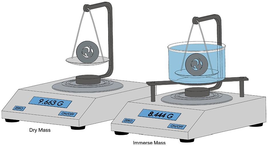
The Archimedes’ principle applied to blanks and coins after minting.
Numerical simulation
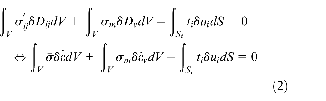
The numerical simulations of coin minting were performed with the in-house finite element computer program i-form.17,18 The program is based on the finite element flow formulation which is built upon the weak form of the quasi-static equilibrium equations,
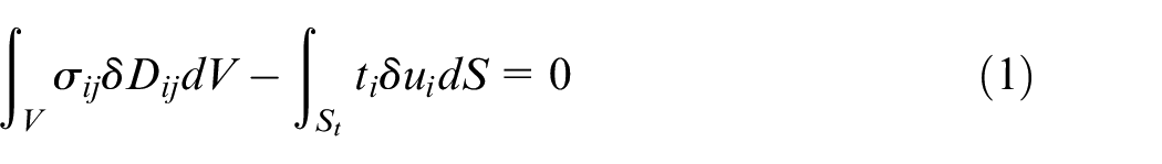
In the above equation
Using the decomposition of the Cauchy stress tensor
In the above equation
The choice of the von Mises yield criterion instead of alternative criteria for porous metals 11 capable of accounting for the changes in relative density during coin minting was due to the fact that the initial relative density of the coin blanks produced by SLM is very close to ‘full density’, as will be seen later in ‘Results and Discussion’.
The computational approach in i-form to handle the second integral term in (2) is by relaxation of the incompressibility condition of the velocity field
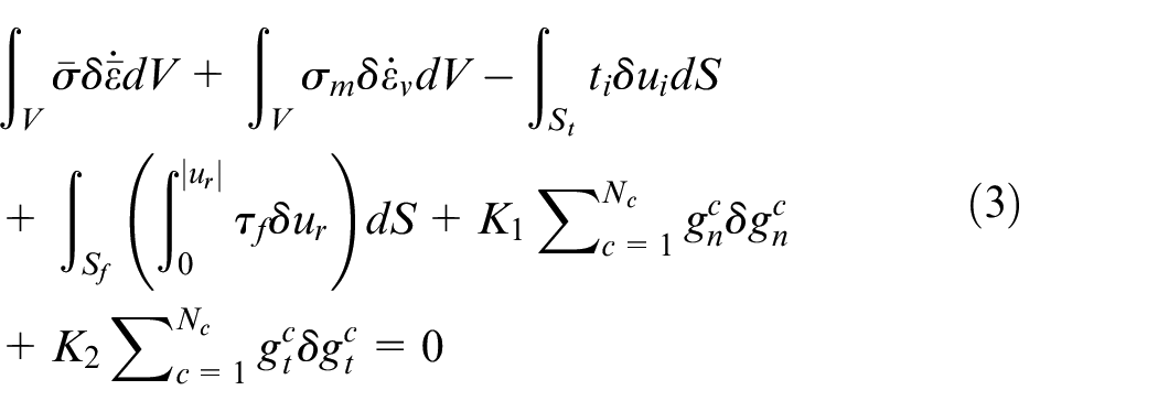
In the above equation, the symbols,
The above described procedure allowed modelling the coin blanks as deformable objects and required discretisation by means of non-structured three-dimensional meshes of hexahedral elements (Figure 7). The meshes of the coin blanks consisted of approximately 110.000 hexahedral elements with four layers of elements across thickness and a higher density of elements in the outer region where lettering was imparted.
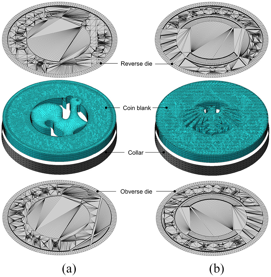
Finite element models of the coin blanks and dies for the (a) ‘Rooster’ and (b) ‘Eagle’ prototype coins.
The dies and collar were modelled as rigid objects and were discretised by means of spatial triangular contact-friction elements. The meshes at centre of the dies are slightly recessed, as in the actual dies, so that contact with the coin blanks preferentially takes place at the outer region where lettering and additional design features are located (Figure 5).
Computer implementation of the finite element flow formulation in i-form required parallelisation of the subroutines handling the solution of the non-linear set of equations resulting from the discretisation of (3) by means of hexahedral elements. The parallelisation was carried out in OpenMP (open shared-memory multiprocessing) and details are given in Nielsen et al. 17
The central processing unit (CPU) time for a typical analysis using a convergence criteria for the velocity field and residual force equal to 10−2 was approximately 48 h on a computer equipped with an Intel i7-5930K CPU processor with six cores.
Results and discussion
Material flow
The first topic to be addressed is the evaluation of the coin minting performance of additive manufactured blanks in conventional press-tool systems. This is done by analysing the finite element predicted evolution of the compressive z-stresses (hereafter designated as the ‘pressure’) in the reverse and obverse surfaces of coin samples corresponding to the four different percentages of the total die stroke that are disclosed in Figure 8.
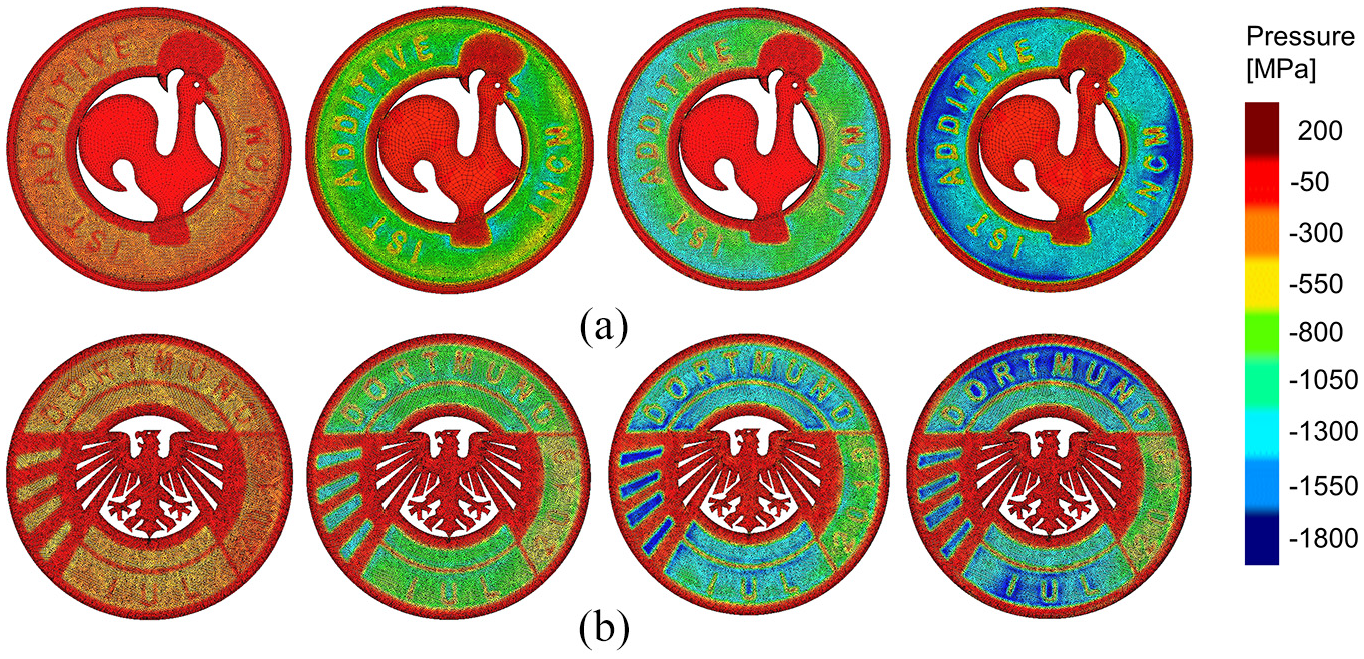
Finite element predicted distribution of pressure (z-stress) (MPa) at 1%, 50%, 75% and 100% of the total die stroke for the (a) ‘Rooster’ and (b) ‘Eagle’ prototype coins.
The dark red colour corresponds to pressures close to zero and, therefore, to regions not in contact with the dies. The other colours evolving from light red to dark blue correspond to increasing values of pressure applied by the dies.
As seen, the centre of both coins remains free of contact up to the end of stroke due to the recesses of 0.15 mm existing in both die surfaces (Figure 5). In contrast, the outer region plastically deforms to fill the intricate details of lettering and other reliefs, and to adjust the diameter of the coin to the geometry of the collar. At the end of stroke, the finite element predicted geometries of the prototype coins are very close to the actual ones (Figure 9).
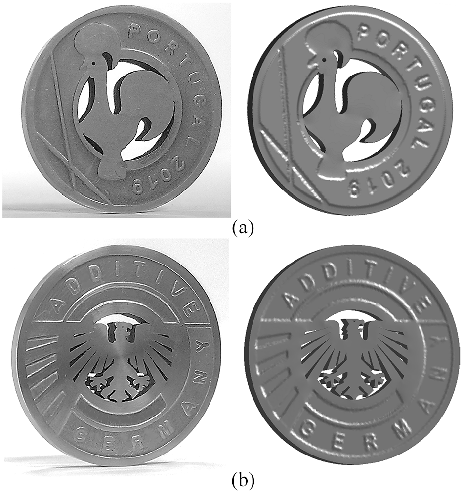
Prototype and finite element prediction of the(a) ‘Rooster’ and (b) ‘Eagle’ coins fabricated from additive manufactured blanks at the end of stroke.
The second topic to be addressed is related to material flow at the centre of the coin blanks containing the complex and intricate contoured holes. Figure 10 shows a top view of the normalised velocity field
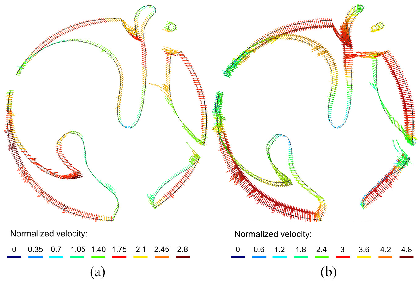
Normalised finite element total velocity vectors for the ‘Rooster’ coin at (a) 100% and (b) 125% die stroke.
However, if the die stroke goes beyond the required end value (Figure 10(b)), the contoured holes start to close progressively and the free sides of the figure may even experience self-contact. This means that the design layout of the additive manufactured coin blanks with contoured holes subject to significant pressures on the entire die surfaces have to include corrections to compensate for their deformation. This applies also to designs with absence of centre recesses in both the coin blank and dies because only with corrections to compensate deformation it is possible to obtain the final desired geometry of the coins.
Although the solution to this problem was somehow obvious, it should be noted that the possibility of minting a coin without applying pressure at the centre opens the possibility for this region to retain the original texture of additive manufacturing, thereby creating innovative aesthetic effects in collector coins. Moreover, it also allows, if the coin blanks are produced one by one directly from additive manufacturing, to incorporate complex three dimensional reliefs at the centre that would be impossible to obtain by coin minting.
These are two important innovative possibilities that are open by the new proposed manufacturing route that combines additive manufacturing and forming.
Forces
Two of the main distinguishing features of coin minting from net-shape close-die forging are the very small die strokes and the fact that forces increase from zero to relatively high values (up to 600 kN) in a few tenths of a millimetre.
Figure 11 presents the experimental and finite element predicted force vs. die stroke evolutions for the two different prototype coins. The agreement is good and the overall results confirm the success of using additive manufactured blanks in coin minting operations.
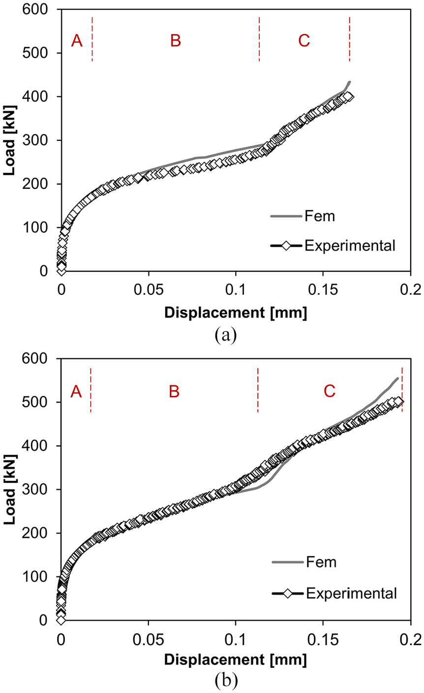
Experimental and finite element predicted evolutions of force with stroke for the prototype (a) ‘Rooster’ and (b) ‘Eagle’ coins fabricated from additive manufactured coin blanks.
The force versus die stroke evolutions allow identifying three well defined stages. A first upsetting stage (labelled as ‘A’) in which the blanks are compressed and material flows mainly outwardly to promote the contact with the collar surface. A second stage (labelled as ‘B’) in which the letters and other reliefs start being filled. A third and final stage (labelled as ‘C’) at the end of coining during which all the reliefs are filled to obtain well-defined features on a brilliant surface finishing. During this last stage the pressures and coining forces rise but at a lower rate than that observed in conventional coins without holes due to generalised material flow constraints of the latter. 19 This is advantageous for the overall life expectancy of the dies and collar.
Porosity
The results of applying the Archimedes’ principle to coin minting are provided in Table 2. The value of relative density
Density of the commercial specimen made from AISI 316L stainless steel and average density of the coin blanks and prototype coins made from the deposited AISI 316L stainless steel.
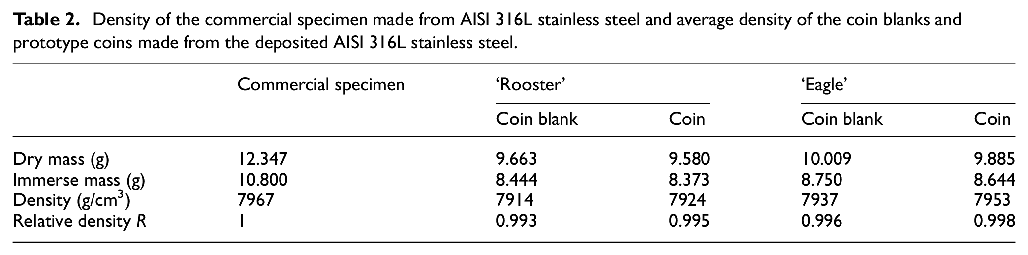
As seen, the relative porosity diminishes during coin minting and the final prototype coins have an almost fully dense structure (
Conclusion
The new proposed approach that combines additive manufacturing, wire electro discharged machining and polishing can be successfully utilised to fabricate coin blanks with complex intricate contoured holes that are not easy (or, even not possible) to be obtained by conventional fabrication routes based on rolling, blanking and edge rimming.
The additive manufactured coin blanks can withstand extreme compressive stresses of approximately 1800 MPa that are typical of coin minting but the force-stroke evolutions do not experience the final sharp increase in force that is typical of coin minting. This is because central coin holes are responsible for diminishing the overall level of pressure and allowing material to flow inwards, instead of being fully constrained. Excessive inward material flow may however induce inadmissible local deformations in the regions of the figures that are adjacent to the contoured holes.
The relative density of the coin blanks increases during coin minting and reaches minimum values of approximately 0.995. However, the original porosity of the coin blanks is already very small due to an adequate deposition strategy that involved sectorial scanning with parallel bi-direction scan vectors that are rotated by 63.5° between layers.
Footnotes
Acknowledgements
The authors would like to acknowledge the support provided by the Portuguese Mint (INCM – Imprensa Nacional Casa da Moeda) and Fundação para a Ciência e a Tecnologia of Portugal and IDMEC under LAETA-UIDB/50022/2020.
Declaration of conflicting interests
The author(s) declared no potential conflicts of interest with respect to the research, authorship, and/or publication of this article.
Funding
The author(s) received no financial support for the research, authorship, and/or publication of this article.