
Abstract
This article is aimed at extending the ‘mortise-and-tenon’ joining concept commonly utilized in corner or tee joints to lap joints in which one sheet is partially placed over another without any change in their shape. The approach makes use of wire arc additive manufacturing to fabricate the tenons and allows various shapes and thicknesses to be made from a wide range of metallic materials. Upset compression of the tenons is utilized to mechanically lock the two sheets being joined. Experimental and finite element simulation works performed with monolithic (aluminium–aluminium) and hybrid (aluminium–polymer) ‘unit cells’ consisting of a single lap joint are utilized to investigate the deformation mechanics and the feasibility of the new proposed joining process. Tensile-shear loading tests were carried out to determine the maximum force that the new proposed joints are capable to withstand without failure. Pull-out forces of approximately 8 and 6 kN for the monolithic and hybrid joints allow concluding on the potential of additive manufactured ‘mortise-and-tenon’ lap joints to connect sheets made from similar and dissimilar materials.
Introduction
Lap joints formed by partially placing one sheet over another without any change in their shape are widely utilized to assemble products from individual parts. These joints are generally manufactured by welding, adhesive bonding and mechanical fastening using one of the specific processes shown in Figure 1.
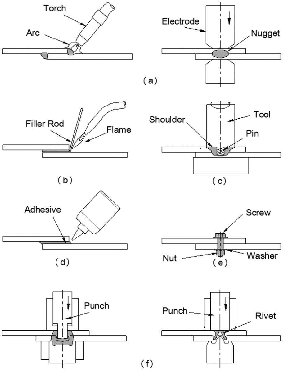
Schematic illustration of various processes utilized to connect two sheets partially placed over one another without any change in their shape: (a) arc and resistance welding, (b) brazing (and soldering), (c) friction stir welding, (d) adhesive bonding, (e) threaded fasteners (and rivets) and (f) clinching and self-piercing riveting.
Welding, 1 for example, comprises fusion welding (e.g. arc and resistance welding, Figure 1(a)), brazing and soldering (Figure 1(b)) and solid state welding (e.g. friction stir welding, Figure 1(c)). Adhesive bonding 2 comprises plain adhesive bonding (Figure 1(d)) and weld-bonding. Mechanical fastening comprises the utilization of threaded fasteners and rivets 3 (Figure 1(e)) and the so-called joining by forming 4 that includes clinching and self-piercing riveting (Figure 1(f)), among other processes.
Each lap joint shown Figure 1 has its own characteristics, advantages and disadvantages, and choosing between them is dependent upon the materials, geometric features, equipment needed and design considerations regarding performance, safety and environment.
Now, bearing in mind the aim and objective of joining two metal sheets (or a metal and a polymer sheet) partially placed over one another along complex paths, without any change in shape, it follows that alternative solutions to conventional welding, adhesive bonding and mechanical fastening need to be developed. This is because the weldability limitations arising from sheet materials with very different chemical, mechanical and thermal properties and the changes in dimensions caused by excessive distortion and warping during the heating–cooling cycles may compromise the overall feasibility and quality of the joints. In case of adhesive bonding, major limitations may also arise from surface preparation, time to cure, long-term durability and environmental requirements. The utilization of mechanical fastened joints is generally constrained by the geometry and variety of the available threaded fasteners or rivets and by the overall size and aesthetics of the resulting joints.
Figure 2 shows a schematic assembly between two sheets made from dissimilar materials in which conventional solutions based on welding seams, adhesive seams and threaded fasteners or rivets (Figure 2(a)) are replaced by the new proposed joining process developed by the authors (Figure 2(b)). The process utilizes lap joints built upon the ‘mortise-and-tenon’ concept and makes use of additive manufactured tenons that are plastically deformed to mechanically lock the two sheets to be joined.
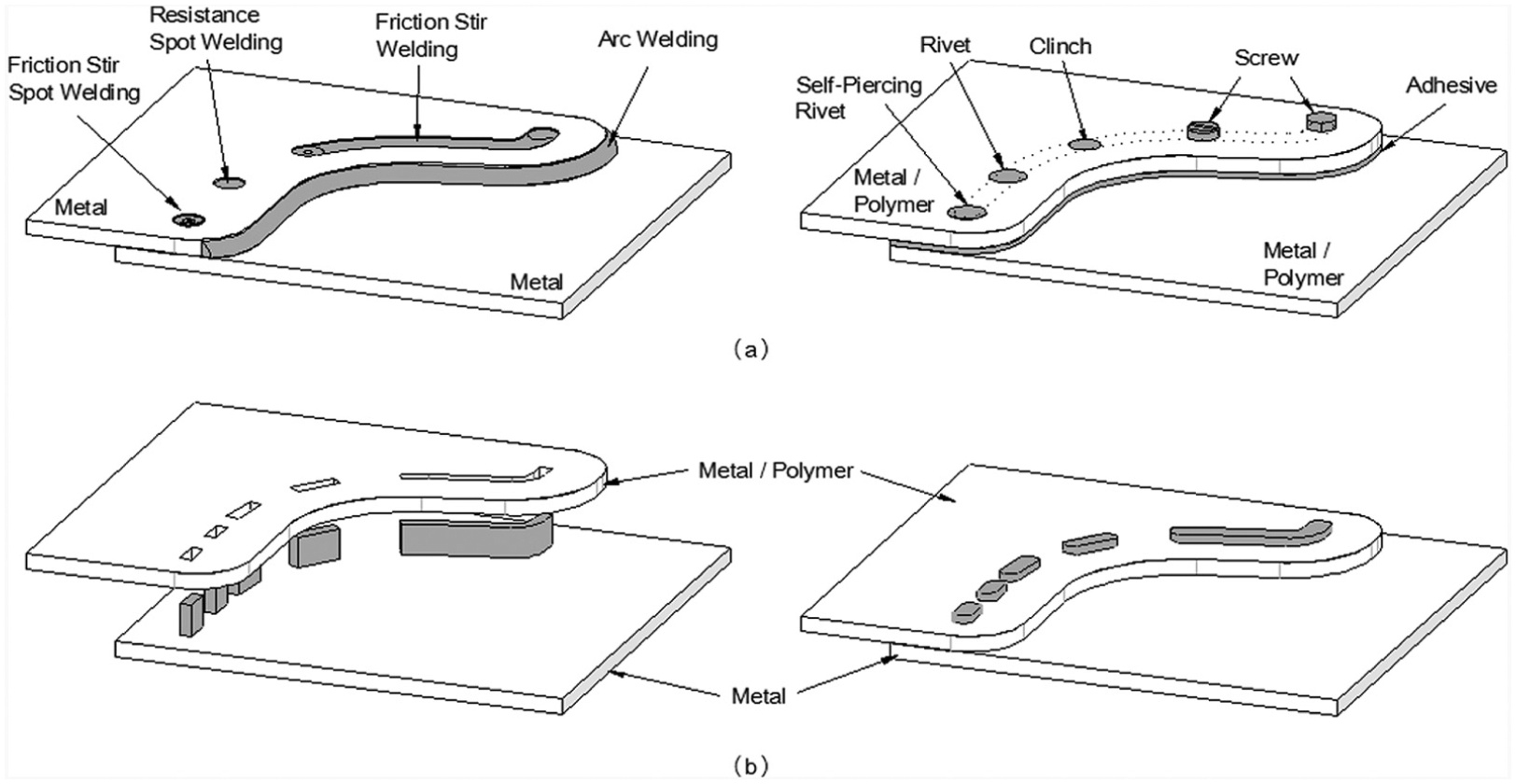
Schematic joining of two sheets partially placed over one another along complex paths by means of (a) conventional processes based on welding (left), adhesive bonding and threaded fasteners or rivets (right) and by means of (b) the new proposed process built upon the ‘mortise-and-tenon’ joining concept that makes use of additive manufactured tenons.
The additive manufactured tenons are deposited on the surface of the metal sheet by wire arc additive manufacturing (WAAM).5,6 The utilization of WAAM instead of electron beam additive manufacturing 7 or laser sintering additive manufacturing 8 is advantageous because it uses standard robotic metal inert gas/metal active gas (MIG/MAG), tungsten inert gas (TIG) or plasma welding systems commonly available in metal working companies. WAAM can also be considered a low-cost process for fabricating tenons due to its high deposition rates and high efficiency 9 resulting from the utilization of welding wire as feedstock instead of using powder bed of fed-based systems.
The combination of the above-mentioned advantages with the flexibility and precision of metal deposition provided by computer numerical control (CNC) 10 allows fabricating tenons of various shapes and thicknesses, repeatedly and economically, along straight or curved (continuous or discontinuous) paths (Figure 2(b)). This is important for applications that comprise the joining of regularly and irregularly shaped parts from sheets partially placed over one another.
In practical terms, and in contrast to fasteners, welding studs and elements, additive manufactured tenons can be tailored to a particular application, not only as to shape and thickness but also by the use of welding-compatible materials with the metal sheets to be joined.
Under these circumstances, the aim and objectives of this article are to present a simple, flexible, low-cost joining process to connect two sheets partially placed over one another, without any change in their shape. The new proposed process is a variant of a previous development of Bragança et al. 11 to connect two sheets perpendicular to one another by means of ‘mortise-and-tenon’ joints cut out from the two sheets. However, and in contrast to the previously developed process that is limited to corner and tee joints, the new proposed joining process is capable of applying for the first time ever the ‘mortise-and-tenon’ concept to the production of lap joints. This is accomplished by combining WAAM and upset compression to fabricate and plastically deform the tenons utilized to mechanically lock the two sheets (Figure 2(b)). Moreover, this innovative utilization of the ‘mortise-and-tenon’ concept to produce lap joints is the reason why the article is built upon lap joints, despite its applicability to setup corner and tee joints.
The first part of the article is focused on the welding parameters of the deposited material of the tenons and on the determination of the stress–strain curves for all the materials utilized in the investigation. The second part of the article starts by characterizing the onset of plastic instability of the additive manufactured tenons subjected to upset compression between two flat parallel platens and continues with the analysis of the overall feasibility of the new proposed joining process by means of finite element simulation and experimentation. Two different types of lap joints are utilized: (1) a monolithic aluminium–aluminium joint and (2) a hybrid aluminium–polycarbonate joint. The third and last part of the article includes experimental data from tensile-shear loading tests that were carried out to determine the maximum force that the new proposed lap joints are capable to withstand before detachment of the two sheets.
Experimentation
The development of the new proposed joining process was supported by experimentation with two different types of lap joints: (1) monolithic metal joints and (2) hybrid metal–polymer joints that make use of aluminium AA5754-H111 and polycarbonate sheets with 5-mm thickness. The tenons were fabricated by WAAM using aluminium AA5356 wire with 1-mm diameter.
Welding parameters
Figure 3 shows a typical deposited metal sample built through the deposition of multi-bead layers with a bead width
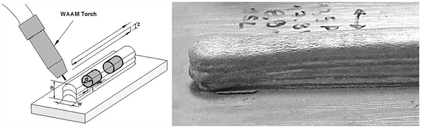
Schematic diagram and deposited aluminium alloy AA5356 from which cylinder test specimens were fabricated by machining.
A KUKA six-axis robotic system using a Fronius CMT VR 7000 cold metal transfer welding machine was utilized for metal deposition. The machine works in controlled dip transfer mode with a lower heat input than that of conventional machines operating in dip transfer mode and is capable of delivering beads with excellent quality without spatter. Computer interfaces are utilized to control the movement of the welding torch and the welding parameters.
The welding torch was programmed with a linear reciprocating motion and its inclination angle was set to 90°. The wire electrode was aluminium AA5356 with 1-mm diameter, and the shielding gas was 99.9% of argon. Table 1 provides the major WAAM parameters that were utilized to fabricate the cylinder test specimens and the tenons.
The WAAM parameters utilized in the investigation.
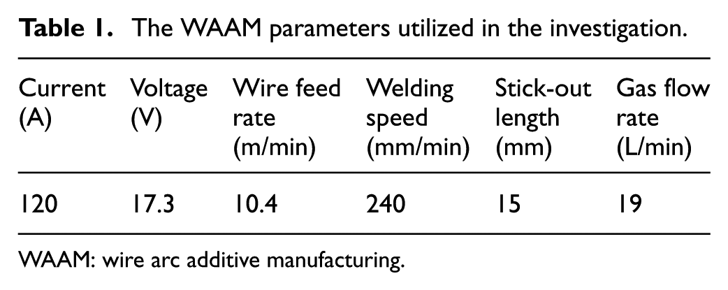
WAAM: wire arc additive manufacturing.
Mechanical characterization of the materials
The stress–strain curve of the deposited aluminium alloy AA5356 was obtained by means of standard compression tests. The cylinder test specimens with 10-mm diameter and 10-mm height were machined out from the sample shown in Figure 3 in the ‘as-deposited’ condition.
The stress–strain curve of the aluminium AA5754-H111 sheets was determined by means of stack compression tests. The stress–strain curve of the polycarbonate sheets was determined by means of tensile and stack compression tests because polycarbonate is a pressure-sensitive polymer. The cylinder test specimens were assembled by piling up three circular discs with 10-mm diameter machined out of the supplied aluminium and polycarbonate sheets by a hole saw. The tensile test specimens were machined out of the supplied sheets in accordance to the ASTM D638 standards. The tests were performed at room temperature on a hydraulic testing machine (Instron SATEC™ 1200 kN) with a cross-head speed equal to 10 mm/min, and the resulting stress–strain curves are shown in Figure 4.
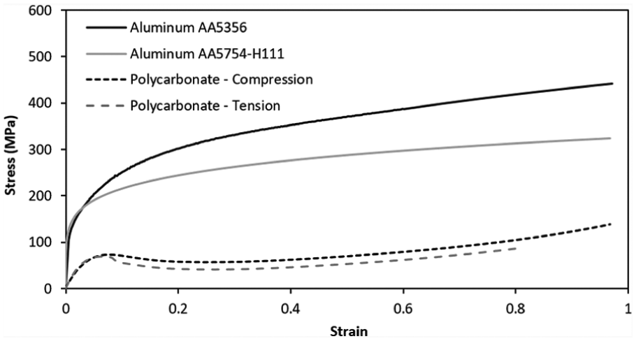
Stress–strain curves of the deposited aluminium AA5356 and of the aluminium AA5754-H111 and polycarbonate sheets.
New proposed joining process
The investigation on the new proposed joining process was carried out in ‘unit cells’ consisting of aluminium AA5356 tenons produced by WAAM and mortises (rectangular cavities) that were cut out in the aluminium AA5754-H111 or polycarbonate sheets. The tenons are longer than they are wider and are machined to their final desired shapes after being deposited. No heat treatment is performed on the tenons. The mortises have straight walls and go all the way through the sheets. The upset compression of the free length of the tenons along the z-axis ensures the mechanical lock between the two sheets to be joined.
As a result of this, the experimental work plan on the new proposed joining process was split into two different parts. The first part was exclusively focused on the upset compression of the additive manufactured tenons and was aimed at determining the operating parameters under which compression can be performed without signs of plastic instability and failure by out-of-plane buckling. This is because the tail of the tenon must plastically deform like a rivet in order to produce a sound flat shaped head during mechanical locking of the two sheets.
The upset compression tests were carried out at room temperature, in displacement control, under a vertical velocity equal to 10 mm/min. The only operating parameter that was analysed was the free length
In what regards the second part of the experimental work plan, the main goal was to demonstrate the effectiveness of additive manufacture to extend the ‘mortise-and-tenon’ concept to the production of lap joints. The tests were performed on the previously mentioned monolithic (aluminium AA5754-H111–aluminium AA5754-H111) and hybrid (aluminium AA5754-H111–polycarbonate) joints and made use of aluminium AA5356 tenons fabricated by WAAM over the aluminium AA5754-H111 sheet. The work plan is summarized in Figure 5 and uses appropriate values of the length-to-width ratio
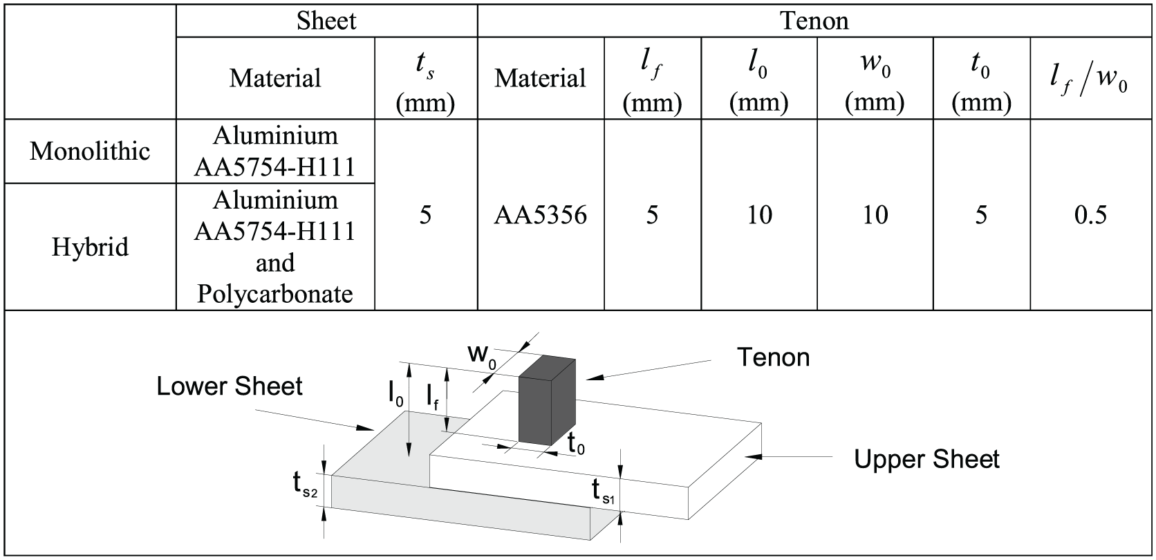
Summary of the experimental work plan to investigate the effectiveness of the monolithic and hybrid joints produced by means of the new proposed joining process.
Finite element modelling
The upset compression of the additive manufactured tenons and the production of the new lap joint built upon a variant of the conventional ‘mortise-and-tenon’ joint 11 were numerically simulated with the in-house finite element computer program I-form. The program is based on the irreducible finite element formulation and is being developed by the authors and validated against experimentation since the end of the 1980s
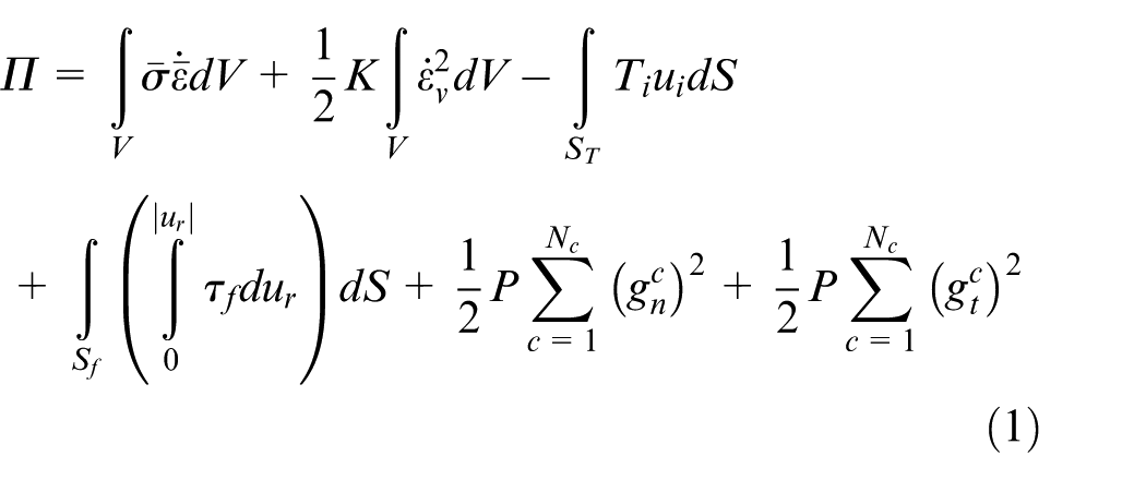
In the above functional, the symbol
The contact between deformable objects (tenons and sheets) is defined by
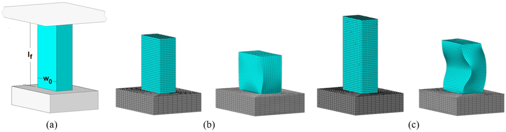
The finite element models that were utilized in the numerical simulation of the upset compression of the additive manufactured tenons and in the connection of sheets by means of the new proposed joining process made use of 3D hexahedral elements. The tenons and the sheets were modelled as deformable objects whereas the tool was modelled as a rigid object and its geometry was discretized by means of contact friction spatial triangular elements. Figure 6 illustrates the upset compression of two different tenons at the beginning and end of deformation.
Finite element modelling of the upset compression of an additive manufactured tenon (Figure 8): (a) schematic representation of the model, (b) geometry of a tenon with a length-to-width ratio
The overall central processing unit (CPU) time for a typical analysis shown in Figure 6 was approximately equal to 3 h on a computer equipped with one Intel i7-5930K CPU (3.5 GHz) processor.
Results and discussion
Upset compression of the additive manufactured tenons
Figure 6 shows two different numerically predicted modes of deformation that develop during the upset compression of additive manufactured tenons. When the slenderness ratio
In case the slenderness ratio
Figure 7 shows the experimental and finite element predicted evolution of the force with displacement for the upset compression of the additive manufactured tenons listed in Figure 8. As seen, the force–displacement evolution discloses two different trends. The tenons with a ratio
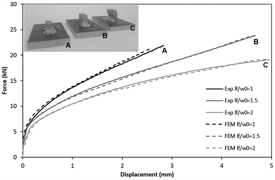
Experimental and finite element predicted evolution of the force with displacement for various additive manufactured tenons with different length-to-width ratios
Summary of the experimental work plan for investigating the upset compression of the additive manufactured tenons.
Lap joints based on the ‘mortise-and-tenon’ concept
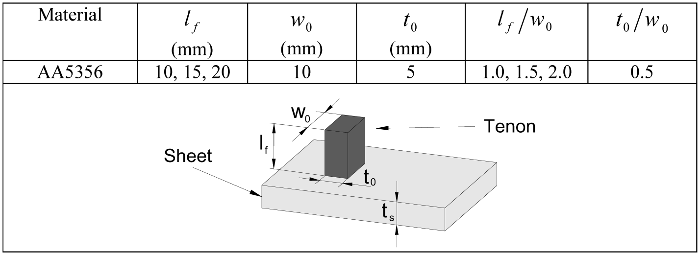
Figure 9(a)–(c) shows the new proposed lap joints based on the ‘mortise-and-tenon’ concept with additive manufactured tenons for connecting two sheets partially placed over one another, without any change in their shape. Figure 9(a) shows the additive manufacture tenon fabricated on top of the aluminium AA5754-H111 sheet, whereas Figure 9(b) and (c) shows the monolithic (aluminium AA5754–H111) and the hybrid (aluminium AA5754-H111–polycarbonate) joints produced by the new proposed process, respectively. The slenderness ratio
Joining two sheets partially placed over one another by the new proposed process: (a) additive manufactured tenon made from aluminium AA5083 and of two mortises cut out in aluminium AA5754-H111 and polycarbonate sheets, (b) lap joint formed between two aluminium AA5754-H111 sheet, (c) lap joint formed between a polycarbonate and an aluminium AA5754-H111 sheet, (d) finite element model corresponding to (b) before and after joining, (e) finite element model corresponding to (c) before and after joining and (f) experimental and finite element predicted force-displacement evolution for both test cases.
Figure 9(d) and (e) shows the corresponding finite element models at the beginning and end of the joining process. The models are limited to the vicinity of the plastically deforming region in order to reduce the overall computational requirements but the correlation between the experimental and numerical predicted evolution of the force with displacement shown in Figure 9(f) is very good. In fact, both experimental results and finite element predictions disclose the required forming force to be smaller in case of the hybrid lap joints probably due to some expansion of the polycarbonate mortise during the upset compression of the aluminium tenon. Still, a sound mechanical lock is formed between the two sheets as will be shown in the following section focused on the tensile-shear loading tests.
Tensile-shear loading tests
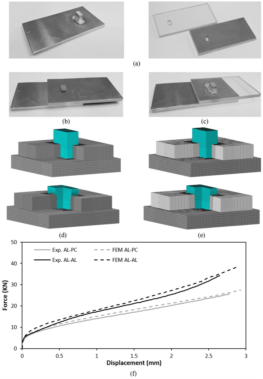
Tensile-shear loading tests were utilized to determine the maximum force that the new proposed joints are capable to withstand without failure. The test is schematically shown in Figure 10(a) together with the monolithic and hybrid joints after being tested.
Tensile-shear loading tests of the new proposed joint: (a) schematic representation of the tensile-shear loading test and joints after being tested and (b) experimental evolution of the force with displacement for the monolithic and hybrid joints.
As seen, the separation of the two sheets is accomplished in two different ways. In case of the monolithic aluminium joint, the sheets are separated by shearing off the tenon along its interface (intermediate zone) with the lower aluminium sheet. The maximum experimental shear force
In order to compare the performance of the new proposed joint with that of conventional riveting, the following expression retrieved from the mechanical design of rivets
14
is utilized to calculate the maximum admissible shear force

In the above equation,
This value is 16% smaller than that obtained in the tensile-shear loading tests performed with the new proposed joint (refer to the dashed line in Figure 10(b)). A possible reason for the difference between
In case of the hybrid (polycarbonate–aluminium) joint, the tensile-shear force to separate the two sheets is smaller and does not drop after reaching its peak value (approximately 6 kN). In fact, it remains practically unchanged because the joint is not destroyed by shearing off the tenon, but by plastically deforming the polycarbonate mortise with the aluminium tenon (refer to Figure 10(a)).
The results obtained with monolithic and hybrid joints prove the feasibility of the new proposed process to extend the concept of ‘mortise-and-tenon’ joints with additive manufactured tenons to the production of lap joints.
Conclusion
The ‘mortise-and-tenon’ fixture commonly utilized in corner or tee joints is successfully extended to lap joints in which one sheet is partially placed over another by the use of tenons fabricated by WAAM. The proposed approach allows fabricating tenons with various shapes and thicknesses in a wide range of metallic materials for applications in simple or complex joining paths.
The feasibility of the new joining process was investigated by means of ‘unit cells’ consisting of a single lap joint of similar (aluminium) or dissimilar (aluminium–polycarbonate) materials. The process window was established as a function of the free length-to-width (slenderness) ratio of the additive manufactured tenons
Destructive tensile (pull-out) tests were utilized to characterize the overall performance of the new proposed lap joints. Two different detachment modes were observed. In case of monolithic aluminium joints, the sheets were separated by shearing off the tenon along the intermediate region with the lower aluminium sheet after being subjected to tensile-shear loads in the range of 8.3 kN. In case of hybrid (aluminium–polycarbonate) joints, the maximum withstandable force drops to approximately 6 kN and separation is accomplished by plastic deformation of the polycarbonate mortise while the tenon is drawn by means of the applied tensile-shear loading.
Results allow concluding that the proposed extension of the ‘mortise-and-tenon’ concept to lap joints has potential to connect sheets made from dissimilar materials with very different chemical, mechanical and thermal properties.
Footnotes
Declaration of conflicting interests
The author(s) declared no potential conflicts of interest with respect to the research, authorship and/or publication of this article.
Funding
The author(s) disclosed receipt of the following financial support for the research, authorship, and/or publication of this article: This work was supported by Fundação para a Ciência e a Tecnologia of Portugal and IDMEC under grants LAETA – UID/EMS/50022/2013 and PDTC/EMS-TEC/0626/2014. I.M.F. Bragana thanks Instituto Politécnico de Lisboa for support (IPL-IDI&CA 2016 – CompSBJ).