
Abstract
Distortion mitigation techniques for large parts constructed by additive manufacturing processes are investigated. Unwanted distortion accumulated during deposition is a common problem encountered in additive manufacturing processes. The proposed strategies include depositing equal material on each side of a substrate to balance the bending moment about the neutral axis of the workpiece and applying heat to straighten the substrate. Simple finite element models are used to predict the effectiveness of the mitigation strategies in order to reduce computation time and to avoid costly experiments. The strategy of adding sacrificial material is shown to be most effective and is then applied to the manufacture of a large electron beam deposited part consisting of several thousand deposition passes. The deposition strategy is shown to reduce the maximum longitudinal bending distortion in the large additive manufacturing part by 91%. It is shown that after the distortion mode of concern is identified, simple finite element models can be used to study distortion accumulation trends relevant to the large part. Experimental observations made here, as well as finite element model results, suggest that the order in which the balancing material is added significantly affects the success of the proposed distortion mitigation strategy.
Keywords
Introduction
Additive manufacturing (AM) processes allow for the construction of metallic parts directly from a digital geometry file without the retooling cost associated with casting and forging. Wire or powder is melted onto a substrate by a laser or electron beam and allowed to cool and solidify to form a fully dense geometry built up on a layer-by-layer basis. The large thermal gradients caused by the deposition process often lead to significant workpiece distortion, especially in large builds, taking the part out of tolerance. In order to combat the issue of process-induced distortion, and in order to make AM processes useful in industry applications, techniques to mitigate distortion in large deposited parts must be developed.
In order to reduce distortion, the appropriate distortion mode must be identified as first defined by Masubuchi. 1 The out-of-plane distortion modes include angular, buckling, and longitudinal bending distortion. Angular and buckling distortion are caused by similar mechanisms. Angular distortion is caused by transverse shrinkage in the deposition region, while buckling occurs when residual stress caused by longitudinal shrinkage exceeds the workpiece critical buckling strength. Both angular and buckling distortion are less common in AM than in welding as the substrates used are generally thicker than weld panels. Of the three possible out-of-plane modes, longitudinal bending is of primary concern in AM processes. The longitudinal bending distortion is caused by the contraction of the molten material after heating and deposition. The progression of substrate distortion during deposition is illustrated in Figure 1. When the molten material is applied, the thermal expansion of the top of the substrate causes bending and plastic deformation, shown in Figure 1(a). The final longitudinal bending of the substrate, displayed in Figure 1(b), is caused by the cooling and contraction of the deposited material. When depositing large parts, the problem of longitudinal bending can be exacerbated by the use of longer longitudinal deposition passes commonly used as a means to reduce processing time. 2 Several methods to reduce distortion incurred during welding and AM processes have been previously investigated.
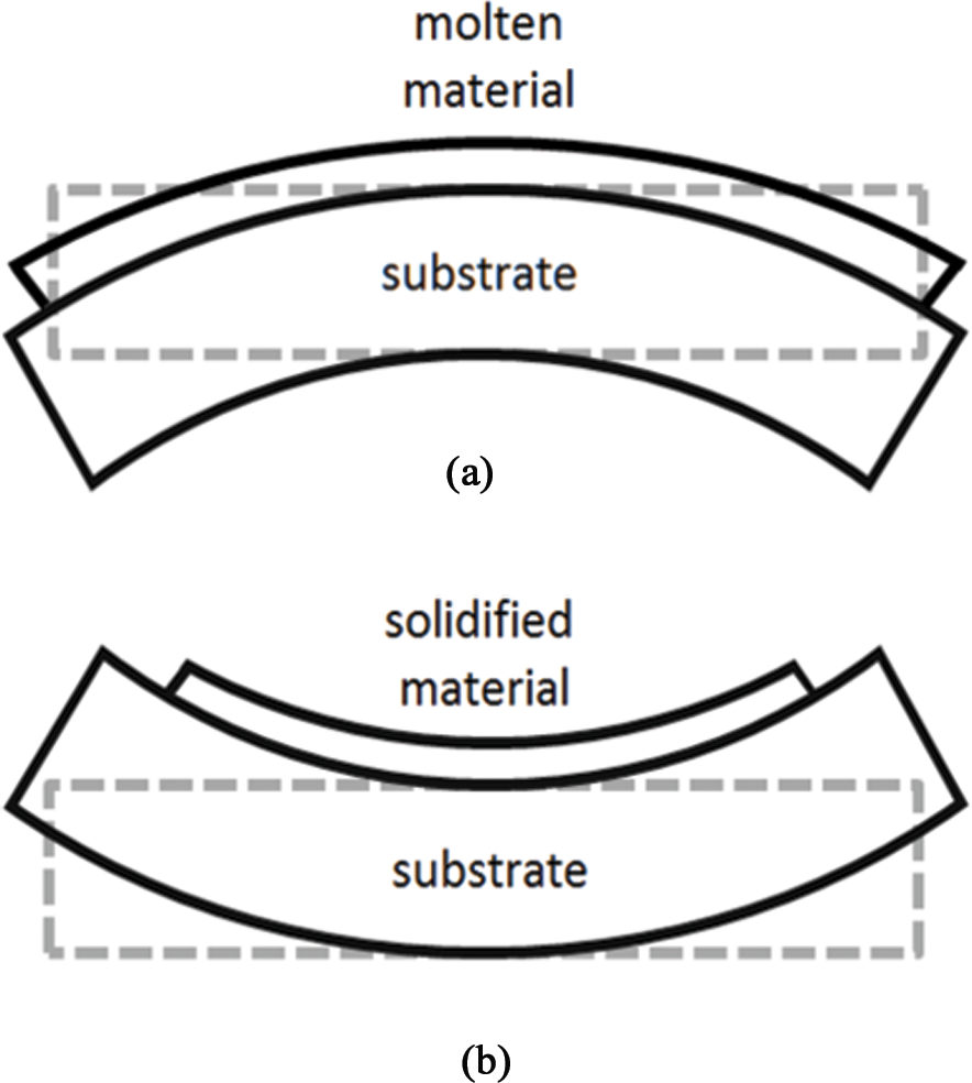
Progression of the substrate distortion throughout the deposition process. The undeformed and deformed substrates are illustrated by dashed and solid lines, respectively: (a) workpiece after the deposition of molten material and (b) workpiece after the cooling of deposited material.
Distortion mitigation techniques used in AM originate from research performed on a similar process, multi-pass welding. In welding research, finite element modeling (FEM) is commonly used to assess the effectiveness of distortion mitigation strategies while avoiding costly trial-and-error iterations. FEM development in welding dates back several decades and has focused on predicting both thermal and mechanical responses of welded panels.3–8 Weld research has shown reducing the heat input, balancing the residual stress to minimize the bending moment, and creating a temperature difference between welded parts (known as transient differential heating) 10 to be effective in reducing longitudinal bending distortion levels. AM differs from multi-pass welding in that AM involves the addition of large volumes of material, resulting in a larger number of deposition passes and longer processing times.
Researchers investigating distortion mitigation techniques in AM have shown that altering the laser scanning pattern can reduce distortion, with shorter deposition passes resulting in lower distortion levels.11–14 However, shorter scanning patterns add processing time by requiring a greater number of deposition passes to add the same amount of material. This problem becomes more significant for large parts with a greater number of deposition passes. Residual stress may be reduced by preheating the substrate and holding it at a high bulk temperature15–17 or by heating the deposition region immediately prior to deposition (localized preheating). 18 Bulk substrate heating is only feasible for small workpieces as it is not practical to hold a large substrate at a high temperature for a long period of time, while localized preheating requires modifications to the laser or electron beam deposition system. Industry applications are frequently focused on large workpieces, but all of the distortion mitigation techniques thus far investigated have only been shown to be effective on models of small parts.
This work investigates three new distortion mitigation techniques, useful for reducing the longitudinal bending distortion mode in large AM parts. The first strategy involves applying heat to the workpiece substrate in an attempt to straighten it after deposition. The subsequent techniques involve depositing equal material on each side of a substrate in order to balance the bending moment about the neutral axis of the workpiece. The added deposition passes used to balance the bending moment are referred to as balancing passes, with the deposition passes needed to construct the actual part geometry referred to as build passes. The balancing passes deposit sacrificial material that is machined away post-process. Because electron beam deposition typically adds significant extra material that is machined away post-process, the additional sacrificial material will not require a prohibitive amount of additional machining time. The second strategy examines the effect of depositing the build passes consecutively after the completion of all balancing passes. The third investigates the possibility of depositing a balancing layer after each build layer is considered. The effectiveness of each technique is investigated using a small finite element (FE) model consisting of fewer than 4000 elements. The techniques found to be most successful on the small model are then applied to the manufacture of a large Ti-6Al-4V electron beam deposited part.
Evaluation of distortion mitigation techniques
The feasibility of applying heat to straighten a substrate or adding additional deposited material to balance the bending moment acting on the substrate was first investigated using differing deposition strategies on small models. Significant computation time was saved using small FE models to predict the effectiveness of different distortion mitigation strategies on large parts when compared with simulating the actual large workpieces.
A brief overview of the model is first provided. Deposition cases are outlined, which allow for the investigation of the aforementioned mitigation techniques. The deposition strategies that successfully achieve significant distortion mitigation on the small models are applied to the manufacture of an actual large part.
Electron beam deposition simulation
A three-dimensional (3D) thermo-elasto-plastic analysis was performed to predict the effectiveness of the presented distortion mitigation techniques. The results of the thermal simulation were imported as a load file into the mechanical analysis, which does not affect the thermal analysis due to the fact that the two are weakly coupled. Electron beam deposition was modeled, as the process is commonly used to deposit large parts due to its ability to quickly deposit large amounts of bulk material. A detailed validation of both the thermal and the mechanical models is provided in Denlinger et al. 19
Thermal analysis
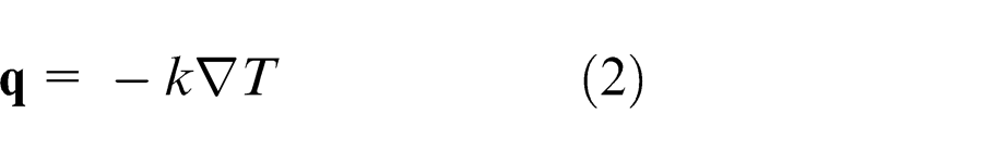
The governing heat transfer energy balance is written as
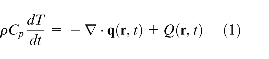
This equation depends on the material density ρ, the specific heat capacity Cp
of the material, the temperature T, the heat source Q, the time t, the relative reference coordinate vector
Heat loss attributable to radiation is calculated as
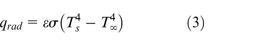
where ε is the surface emissivity, σ is the Stefan–Boltzmann constant, Ts is the surface temperature of the workpiece, and T ∝ is the ambient temperature. A constant emissivity of 0.54 was used in the simulations. 19 Convection was not present, as the electron beam deposition process takes place in a vacuum chamber.
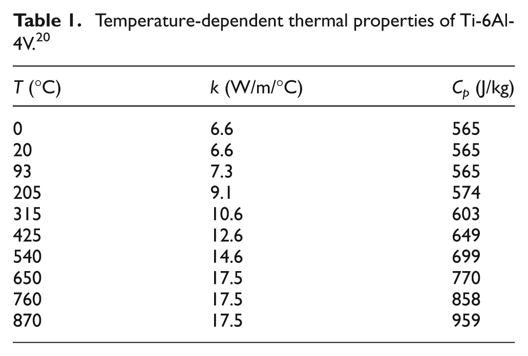
The temperature-dependent thermal material properties for Ti-6Al-4V are listed in Table 1. Properties at temperatures between those listed were determined by linear interpolation over the temperature range, and values at temperatures above those listed were assumed to be the nearest tabulated value. Density ρ was set as a constant 4.43 × 10⁻⁶ g/mm3.
Temperature-dependent thermal properties of Ti-6Al-4V. 20
Elasto-plastic mechanical analysis
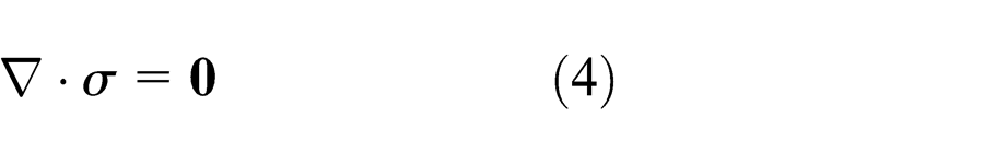
Once the thermal simulation was complete, the results were imported into the mechanical analysis. A quasi-static incremental analysis was performed. The stress equilibrium equation is
where
The mechanical constitutive law is
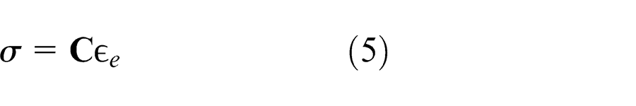
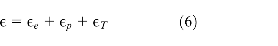
where
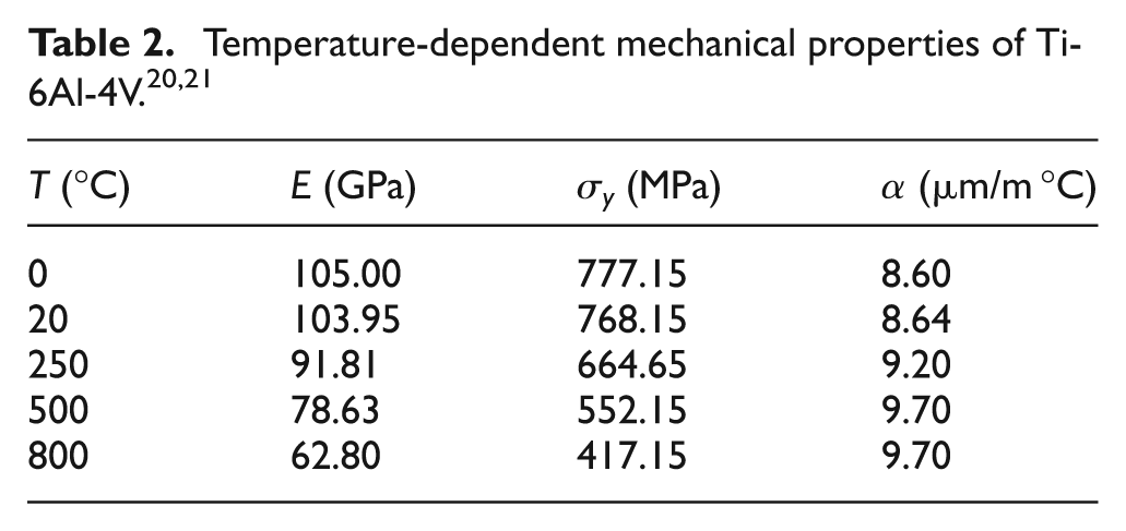
Table 2 lists the temperature-dependent mechanical properties for Ti-6Al-4V used in the model, including the elastic modulus E, the yield strength σy , and the coefficient of thermal expansion α. A constant value of 0.34 was used for Poisson’s ratio.
Numerical model
A 203.2-mm-long × 28.6-mm-tall × 12.7-mm-wide wall was constructed on the topside of the substrate, and a 203.2 × 6.35 × 12.7-mm wall was built up on the backside of the substrate, as large and complex industry parts commonly require material to be placed on both sides of the substrate. Also, the part investigated in section “Results and discussion” possesses nine layers and two layers on the top and bottom of the substrate, respectively. The depositions were made upon a 254-mm-long × 101.6-mm-wide × 12.7-mm-thick substrate using unidirectional longitudinal passes. The part dimensions, which are arbitrary, were chosen to be sufficiently small to allow for the model to be discretized into fewer than 4000 elements, thus keeping simulation times feasible. A cooling time of 1200 s occurred between the deposition of each layer. On large parts, long cooling times are typical because each deposition layer can be time-consuming, allowing the deposited material to cool significantly as the layer is completed. All meshes were generated using Patran 2012 by MSC. The thermal and mechanical analyses were performed using CUBES by Pan Computing LLC. The electron beam heat source was modeled using the Goldak double-ellipsoid model as follows
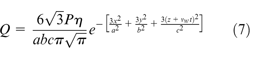
where P is the electron beam power; x, y, and z are the local coordinates; a, b, and c are the transverse, melt pool depth, and longitudinal dimensions of the ellipsoid, respectively; vw is the heat source travel speed; and t is the time. The laser spot size is 6.35 mm and penetrates to a depth of 3.81 mm, 19 making a and c equivalent to 6.35 mm and b = 3.81 mm. The absorption efficiency η for Ti-6Al-4V deposited using the electron beam system is 0.9. 19
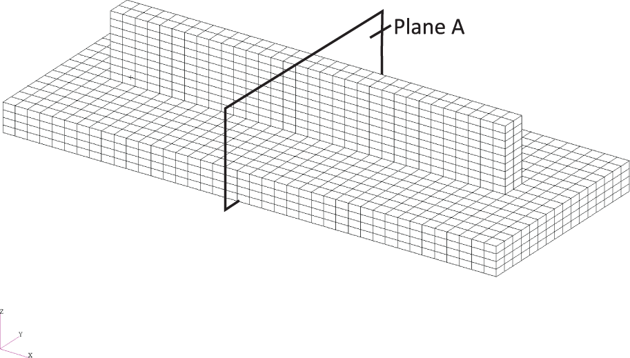
The addition of deposited material was simulated using the quiet element approach where all elements begin as part of the simulation; however, elements belonging to the deposited material are given material properties such that they do not affect the analysis until contacted by the heat source. Surface radiation was applied to all free surfaces, including those on the evolving surface between active and quiet elements. The heat source has a power P of 8 kW and moves at a speed vw of 12.7 mm/s. After the completion of the build, the parts are cooled to room temperature. The model was mechanically constrained as cantilevered allowing distortion to be monitored at a node on the free end of the substrate, as shown in Figure 2, to compare the different deposition strategies.
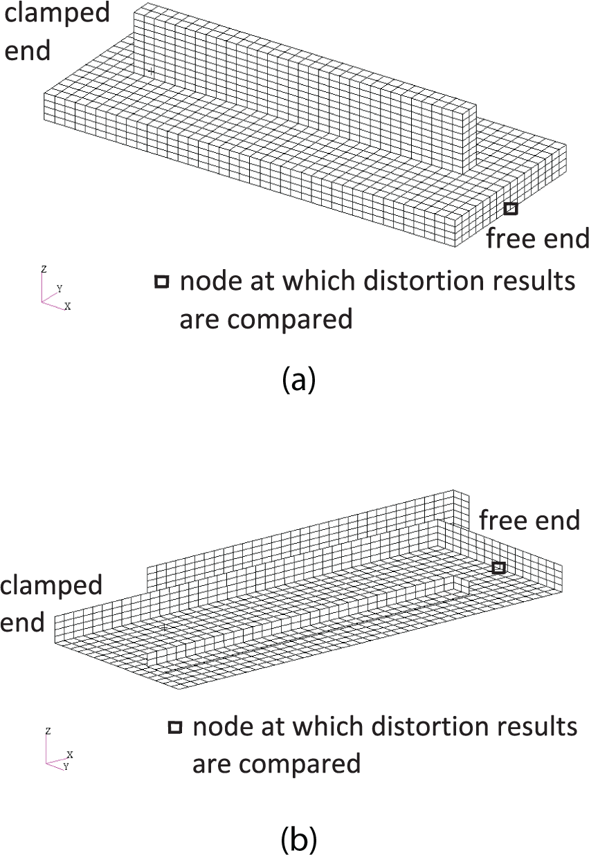
Mesh showing the node observed to monitor distortion: (a) isometric view showing the top of the workpiece and (b) isometric view showing the bottom of the workpiece.
Deposition strategies
Four cases were studied to determine the effectiveness of several mitigation strategies. Straightening the substrate by applying only heat and depositing additional material to balance the bending moment was compared to a baseline case. For actual builds, in the cases where additional material is deposited, the extra material is sacrificial and would be machined away post-process. A detailed description of each case is provided, and the cases are summarized in Table 3.
List of the cases.

A three-step convergence study was performed on the baseline case comparing the discretization of the mesh using 1, 2, and 4 elements per heat source radius. Using 2 and 4 elements per heat source radius resulted in an increase in distortion of 2.8% and 3.1% when compared to 1 element per heat source radius, respectively. Thus, 1 element per heat source radius was chosen.
Case 1: baseline with topside deposition only
Figure 3 shows the baseline case (case 1). Nine layers and two layers were deposited on the topside and backside of the substrate, respectively, as labeled in Figure 3. The mesh was composed of 3264 elements and 4574 nodes. No attempt was made to reduce distortion accumulated during the deposition of material.
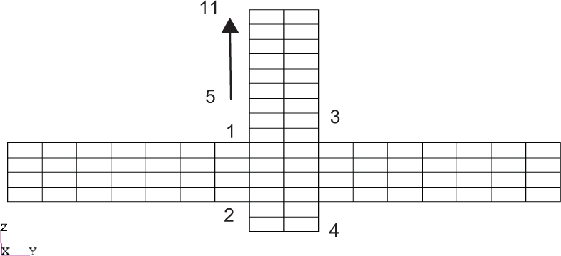
Baseline deposition pattern (case 1).
Case 2: topside heating after each topside layer
Figure 4 shows case 2 which applied topside heating in an attempt to lessen distortion of the part without adding additional material. The mesh was composed of 3264 elements and 4574 nodes. After the deposition of each unbalanced deposition layer on the topside of the substrate, two heating passes each 203.2 mm long were performed. The longitudinal bending distortion caused by the thermal expansion of the top of the substrate was intended to counter the distortion caused by the contraction of the molten material.
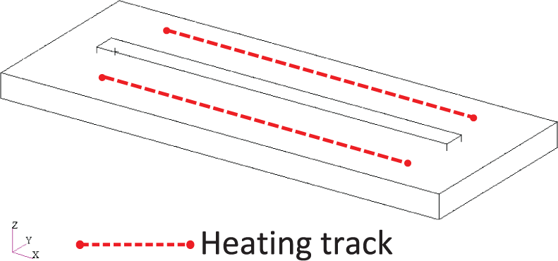
Topside heating with no sacrificial material added (case 2).
Case 3: backside deposition after topside layers deposited
Case 3, whose deposition pattern is seen in Figure 5, used consecutive balancing layers on the backside of the substrate to balance the build layers. The first two build layers on the topside of the substrate and the two build layers on the backside of the substrate were deposited in an alternating fashion. Then, the remaining seven build layers on the topside of the substrate were deposited sequentially followed by seven consecutive balancing layers on the backside of the substrate. The mesh has 3712 elements and 5267 nodes.
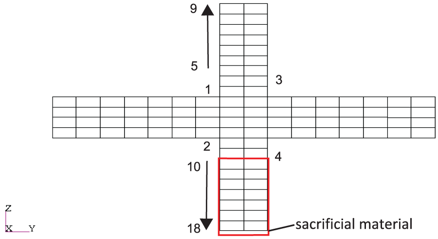
Sequential deposition pattern (case 3).
Case 4: backside deposition after each topside layer
Case 4, shown in Figure 6, examined the possibility of mitigating distortion by depositing a balancing layer on the backside of the substrate after each build layer on the topside of the substrate in order to continually balance the bending moment about the neutral axis of the workpiece throughout the build.
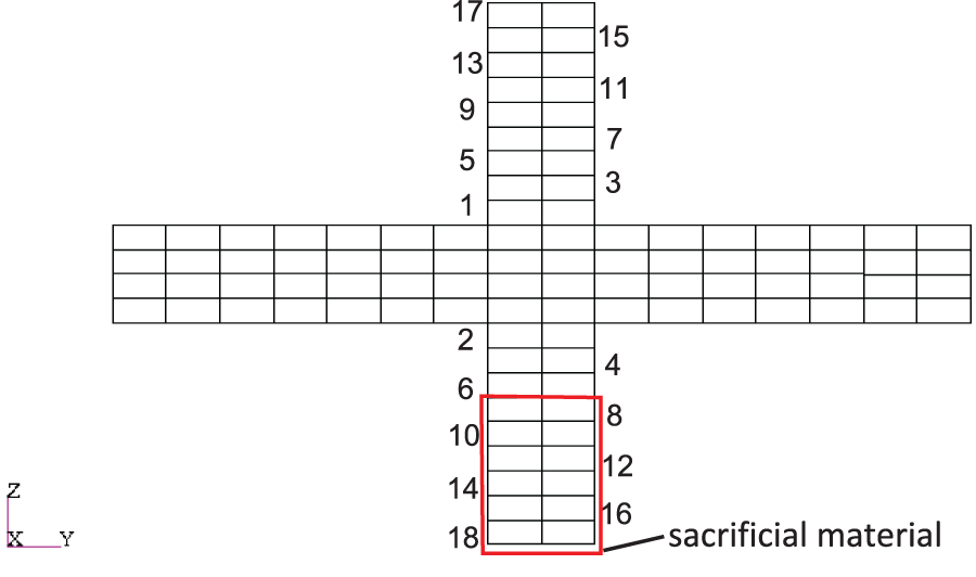
Alternating deposition pattern (case 4).
The end result was a workpiece with a nine-layer high wall on each side of the substrate. When the balancing layers cool after deposition, the bending moment caused by the contraction of the molten material of the balancing layers equals the bending moment caused by the contraction of the molten material making up the build layers and thus may help to straighten the substrate. The mesh consists of 3712 elements and 5267 nodes.
Small model results
Distortion
Figure 7 plots the results of case 1, the baseline case, to illustrate how distortion is being quantified. In each case, the maximum substrate distortion occurred at the free end of the cantilevered substrate. Table 4 summarizes the results of the simulations.
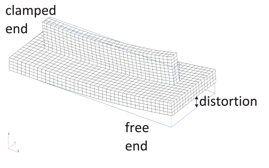
Final distortion for the baseline case (case 1).
Distortion results for the small models.
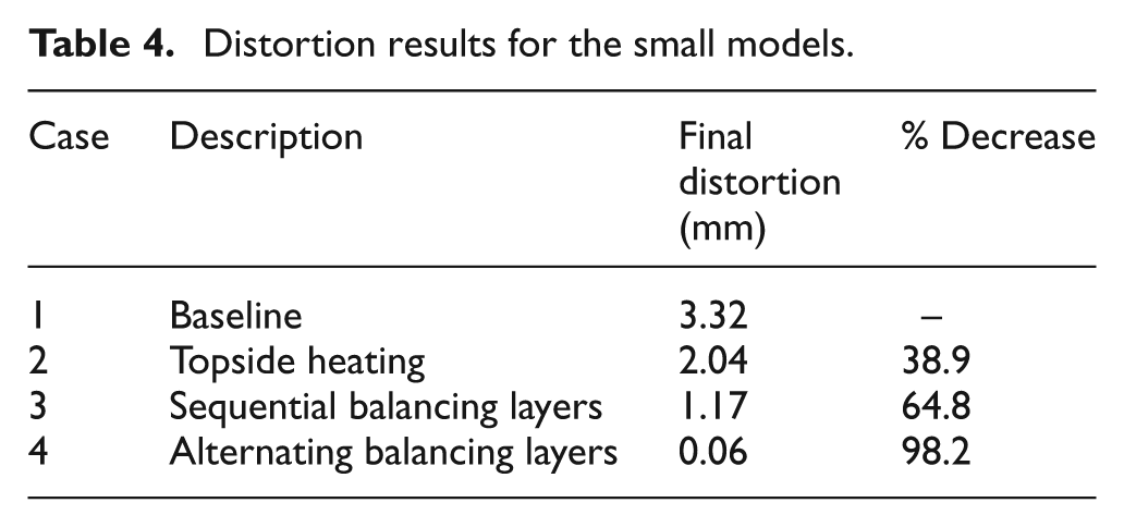
For case 1, the baseline where nine and two layers were deposited on the topside and backside of the substrate, respectively, it can be seen in Figure 8 that nearly no distortion accumulated after the first four deposition layers (around 4900 s) as the bending moment remained balanced about the neutral axis of the substrate. The remaining seven deposition layers on the topside of the substrate caused a final distortion of 3.32 mm.
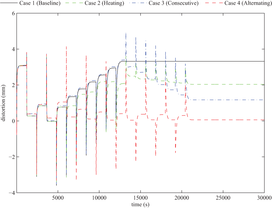
In situ distortion for cases 1–4.
Applying topside heating to the model in case 2 resulted in a final distortion of 2.04 mm, a 38.9% decrease compared with the baseline. The in situ distortion results from case 3, applying sequential balancing layers, shows that distortion accumulated in the build until 12,000 s at which point the balancing layers began to reduce the distortion. The balancing layers were unable to mitigate all distortion and resulted in a final distortion of 1.17 mm, which represents a 64.8% reduction in distortion relative to the baseline case.
Case 4, using alternating balancing layers, can be seen to have accumulated little distortion throughout the build. The balancing of the bending moment after each deposition layer resulted in a final distortion of 0.06 mm, representing a 98.2% reduction in distortion compared with case 1, the baseline case.
The results from the small model suggest that balancing the bending moment about the substrate by adding material is the most capable method of those explored for reducing distortion in AM workpieces. The method yielded superior results when compared with applying only heating.
The distortion mitigation was achieved when the deposited balancing layers cool from their molten state and shrink to form a fully dense deposition, essentially canceling out the distortion caused by the build layers as illustrated in Figure 9. The evolution of substrate distortion is responsible for the peaks and valleys seen in the in situ distortion results in Figure 8.
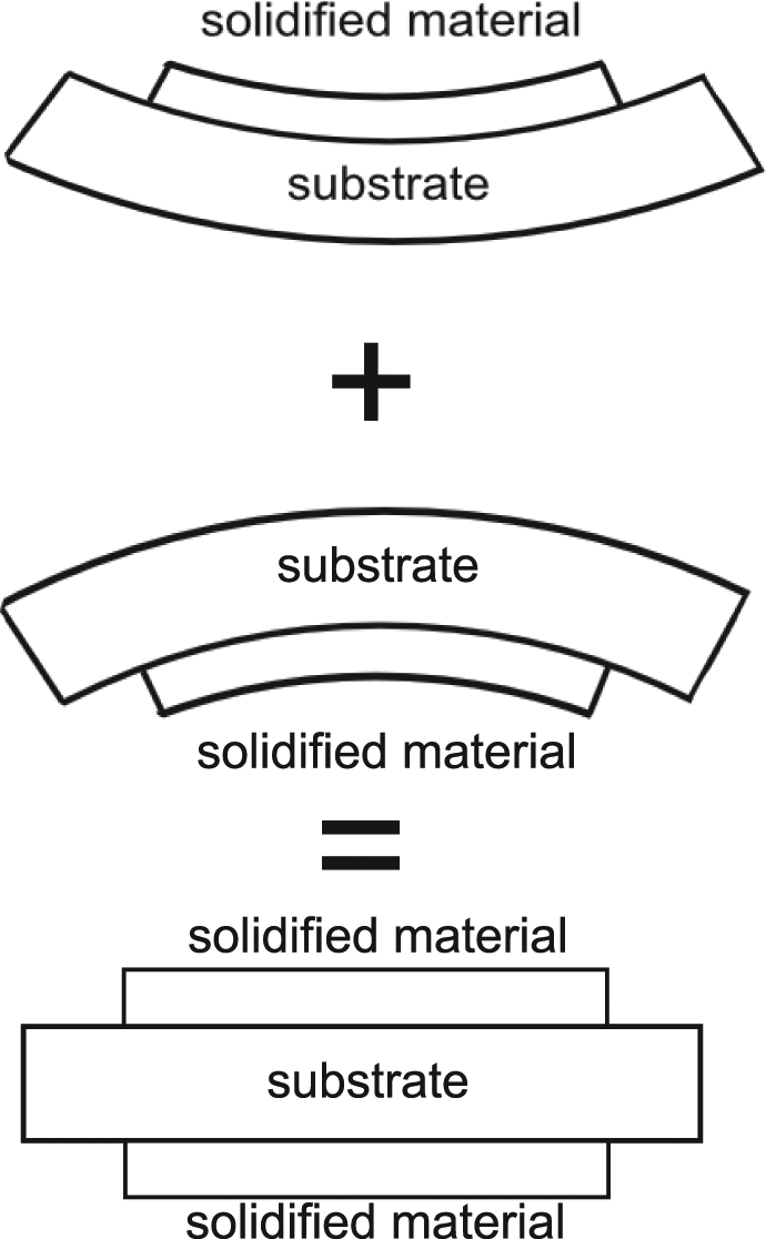
Evolution of substrate distortion during deposition and solidification leading to reduced distortion of the workpiece.
The observed accumulation of distortion in the models indicates that the sequence in which the balancing layers are added is important. The balancing layers in case 3, which were deposited sequentially, resulted in significant distortion mitigation; however, the balancing layers in case 4, which were deposited in an alternating fashion, eliminated nearly all distortion attributed to the deposition of the build layers. The alternating balancing layers in case 4 eliminated significantly more distortion than their sequentially deposited counterparts in case 3. This result suggests that depositing the build layers and balancing layers in an alternating manner can be used to eliminate virtually all longitudinal bending distortion.
Residual stress
Distortion built up during electron beam processing is driven by the accumulation of residual stress due to large thermal gradients during the deposition process. An understanding of how the alternating balancing layers in case 4 eliminate more distortion than the consecutive balancing layers in case 3 can be gained by examining the residual stress results from the model. The residual stress results are compared along the cross-section in Figure 10. The residual stress distribution in case 1, the baseline case, is shown in Figure 11. After the deposition of layer 4, the residual stresses were balanced about the center of the substrate, as seen in Figure 11(a). Figure 11(b) shows that after the remaining seven layers were deposited, the contraction of the additional molten Ti-6Al-4V on the top of the substrate pulled the top of the substrate into compression, leading to a high level of upward bowing distortion. In case 2, which applied only heating to counter substrate distortion, the thermal expansion of the substrate was not adequate to overcome the stress generated by the contraction of the molten metal upon cooling, making it the least effective of the investigated strategies.
Cross section, located at x = 101.6 mm, at which residual stress results are analyzed.
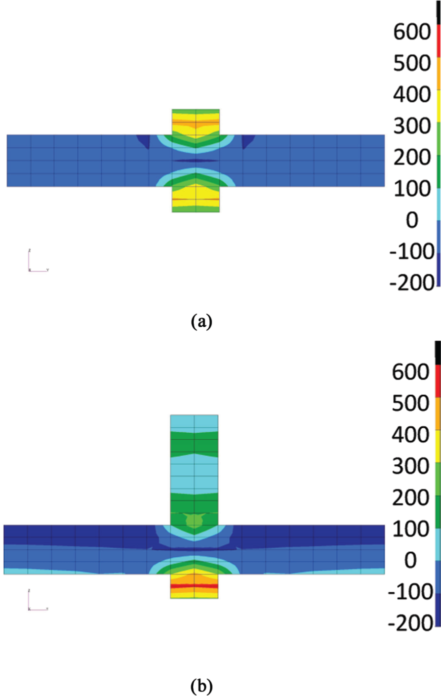
Residual stress (MPa) results for the baseline case 1: (a) residual stress distribution after four layers are deposited, two on the top and two on the bottom and (b) post-process residual stress distribution.
Figure 12 displays the residual stress distribution in the workpiece when applying the consecutive balancing layers in case 3. Prior to the addition of the balancing layers, the residual stress distribution was identical to that plotted in Figure 11(b). The sacrificial layers added entered into tension upon cooling, exerting a compressive force on the bottom side of the substrate as shown in Figure 12(a). The compressive residual stress acted to eliminate a portion of the upward bowing of the substrate. Figure 12(b) illustrates that when all of the sacrificial material has been deposited and permitted to cool, the added contraction of the molten material was unable to counter the residual stress above the neutral axis of the substrate, meaning there will be an upward bow of the substrate.
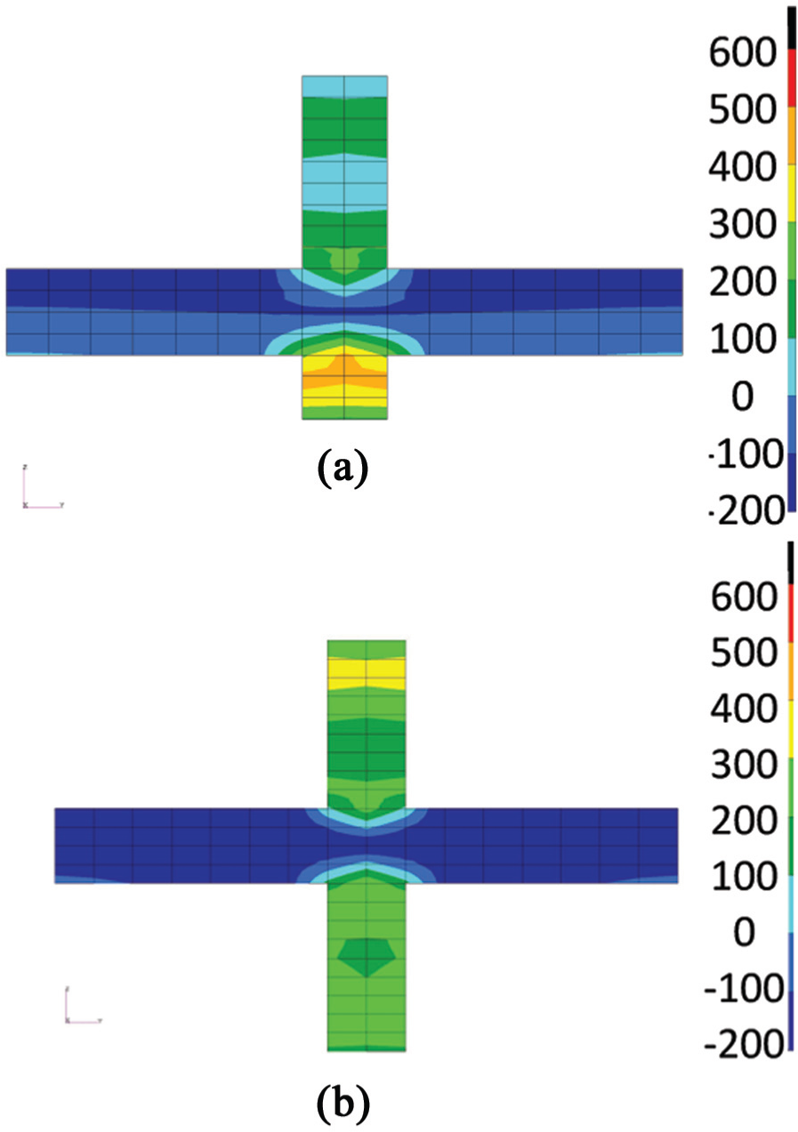
Residual stress (MPa) results when using consecutive balancing layers (case 3): (a) residual stress distribution after 12 layers are deposited, 9 on the top and 3 on the bottom and (b) post-process residual stress distribution.
Unlike the addition of consecutive sacrificial layers, alternating sacrificial layers were able to balance the residual stress about the neutral axis of the substrate throughout the build. Figure 13(a) shows that after the deposition of 12 total layers, the residual stress was nearly uniform through the thickness of the substrate, that is, there was little bowing distortion. As the additional layers were added, the balance of residual stress was maintained throughout the deposition, ending with the substrate in uniform compression through the thickness in its post-process state as illustrated in Figure 13(b).
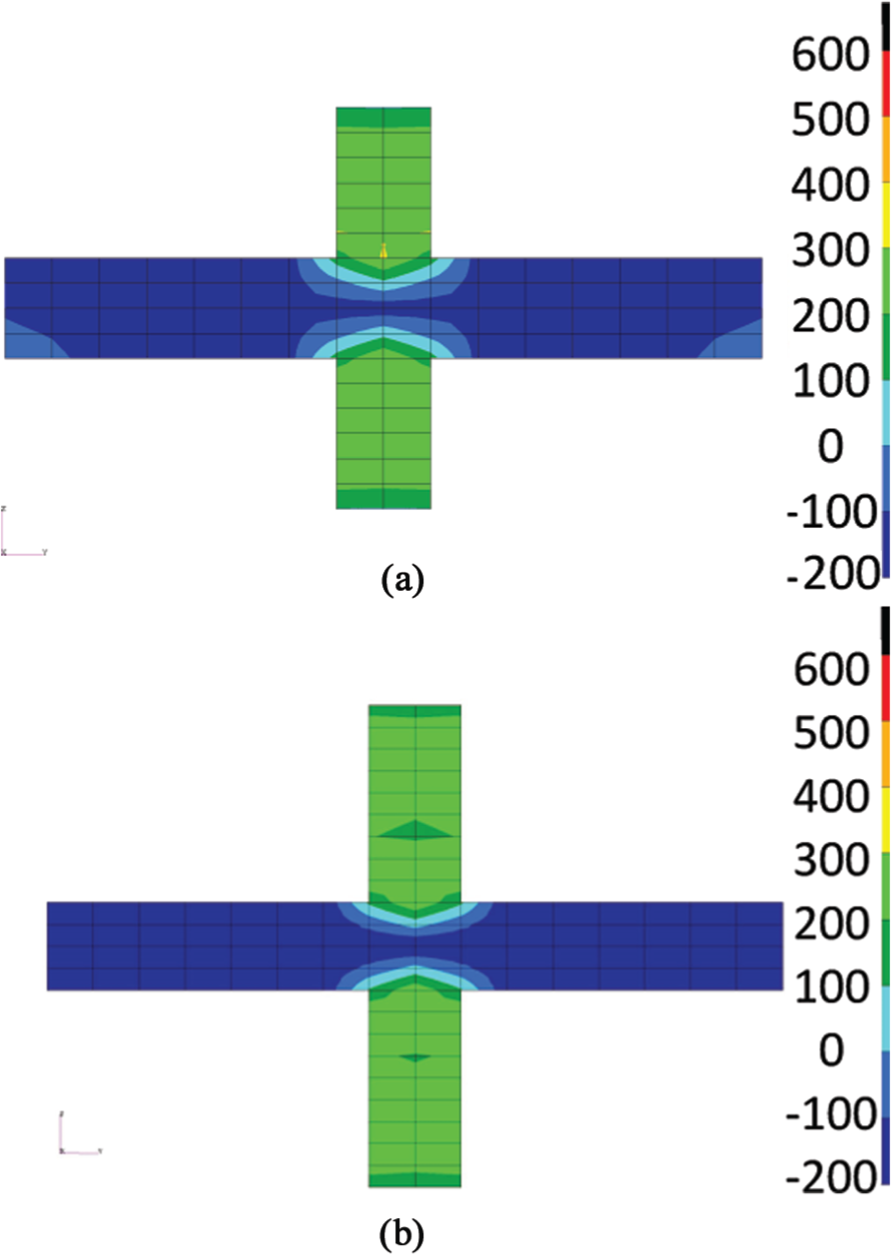
Residual stress (MPa) results when using alternating balancing layers (case 4): (a) residual stress distribution after 12 layers are deposited, 6 on the top and 6 on the bottom and (b) post-process residual stress distribution.
Mitigation techniques applied on a large part
To further investigate the effectiveness of the distortion mitigation strategies presented, a large electron beam deposited build was constructed twice to study whether the most successful strategies from the small models result in similar distortion reduction on a larger scale.
Experimental procedure
An electron beam freeform fabrication system was used to deposit 9.5-mm-diameter Ti-6Al-4V wire feedstock material, at a rate of 0.85 mm/s, in a vacuum chamber, to form the workpiece shown in Figure 14. The AM system used was the Sciaky VX-300, which welds in a vacuum in the range of 10−4–10−5 Torr. The work envelope was approximately 5.8 × 1.2 × 1.2 m3 in volume. The electron beam power was varied from 8 to 10 kW in order to control the melt pool size. The largest builds were deposited 80 layers high, with a total deposition layer count of 107. A Ti-6Al-4V plate of 3810 mm long, 457 mm wide, and 25.4 mm thick was used as a substrate. Two parts, parts A and B, were deposited on each substrate during the build. Two builds were performed, build 1 and build 2, allowing for a total of four parts to be manufactured. Post-process scan results taken by Neomek, Inc. quantified the distortion using a Surphaser Laser with an accuracy of ±0.5 mm.
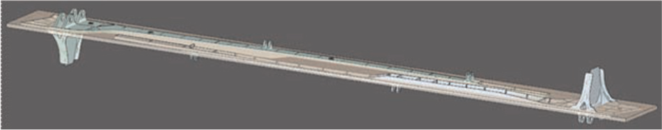
Large deposited part.
Figure 15 shows the test fixture used. The substrate was placed on the fixture and held in place by 40 evenly spaced clamps. The clamps have a spring constant of 22.5 N/mm, allowing for in situ distortion of the substrate. The fixture can rotate to allow for deposition on both sides of the substrate.
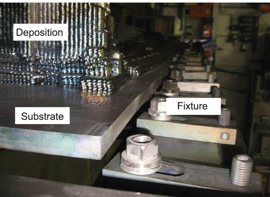
Fixture used to constrain the substrate during deposition.
Deposition cases
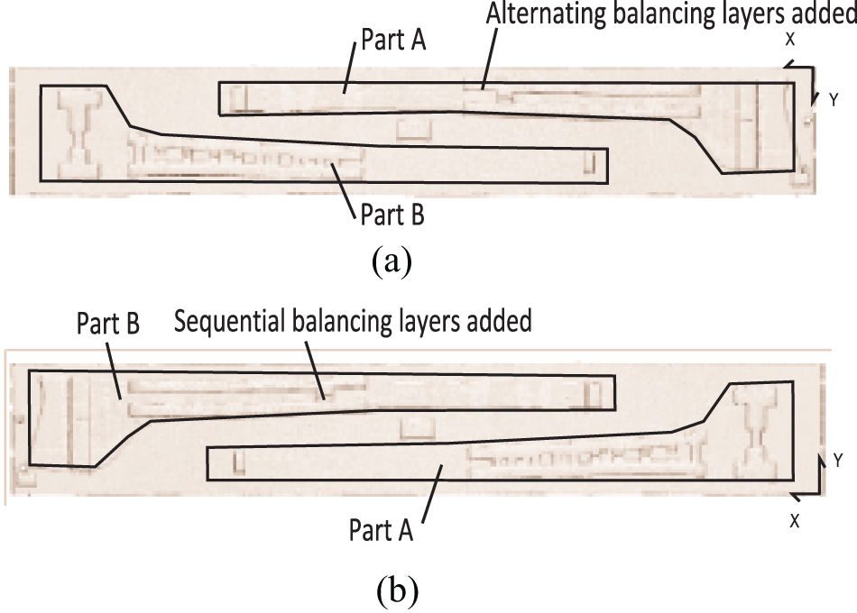
Due to the effectiveness of the distortion mitigation strategies applied on cases 3 and 4, these same strategies were implemented on a large part. The new cases, L2 and L3, were deposited using scan patterns which deposit balancing layers sequentially and alternatively, respectively, and compared to a new baseline deposition case L1. These cases are summarized in Table 5.
Case descriptions for the large part.
Case L1
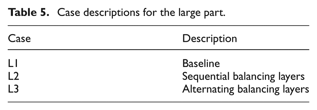
Figure 16 shows case L1 which was applied to build 1 and excluded the use of balancing layers. The deposition strategy is the same as that applied in case 1 and was applied to both parts deposited on the substrate of build 1 making parts A and B identical. Case L1 is the baseline case used to determine the effectiveness of the distortion mitigation strategies. The layers on case L1 which were responsible for the majority of the longitudinal bending distortion of the workpiece have been identified in a previous FEM work by Denlinger et al. 2 and are labeled in Figure 16.
Schematic diagram of the large build illustrating both parts deposited on build 1 (case L1): (a) top view and (b) bottom view.
Cases L2 and L3
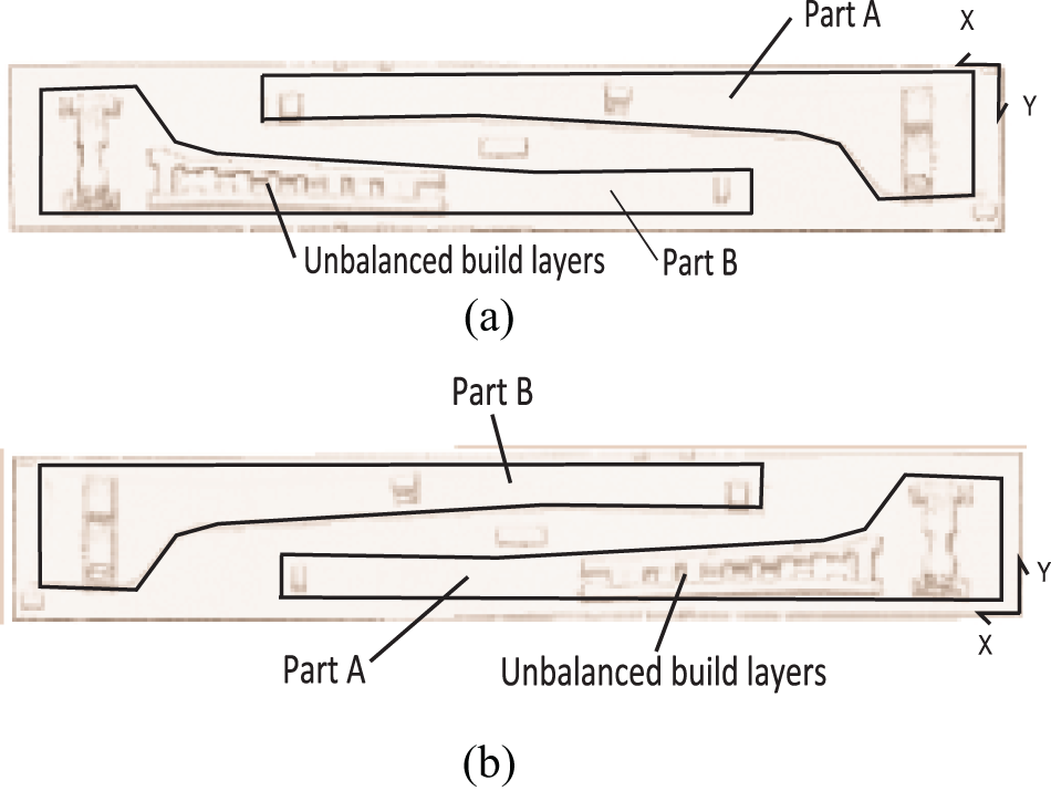
Case L2 employed a strategy that is analogous to that of case 3 and applies sequential build layers, followed by sequential balancing layers. Figure 17(b) shows the additional layers added to part B of build 2. After all build layers were added to the part, it was turned over to allow for the addition of the balancing layers. This strategy required fewer rotations of the part and thus reduces processing time.
Schematic diagram of the large build illustrating both parts deposited on build 2 (cases L2 and L3): (a) top view of build 2 showing the added alternating deposition layers used to balance the part and (b) bottom view of build 2 showing the added sequential deposition layers used to balance the part.
The deposition strategy used for case L3 was identical to case 4, using alternating build layers and balancing layers. The strategy was applied to part A of build 2 as shown in Figure 17(a). After the completion of each build layer, the part was physically turned over to allow for the deposition of a balancing layer and then returned to its initial position to resume the deposition of the next build layer. After the completion of the deposition of the two builds, post-process scan results were taken by Neomek, Inc. to allow for the workpiece distortion levels to be quantified.
Results and discussion
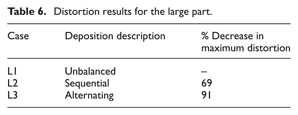
The distortion results are plotted in Figure 18. Case L1, the unbalanced deposition applied to build 1, accumulated a maximum of 37.2 mm of distortion on part A and 32.6 mm on part B. Cases L2 and L3 were implemented on parts B and A of build 2, respectively. Case L2 resulted in distortion levels as high as 10.2 mm on part B. Case L2 has a maximum distortion of 69% smaller than case L1. Case L3 deposition pattern resulted in a maximum substrate distortion of 3.3 mm on part A, representing an 91% decrease in distortion compared with the baseline case. Table 6 summarizes the results.
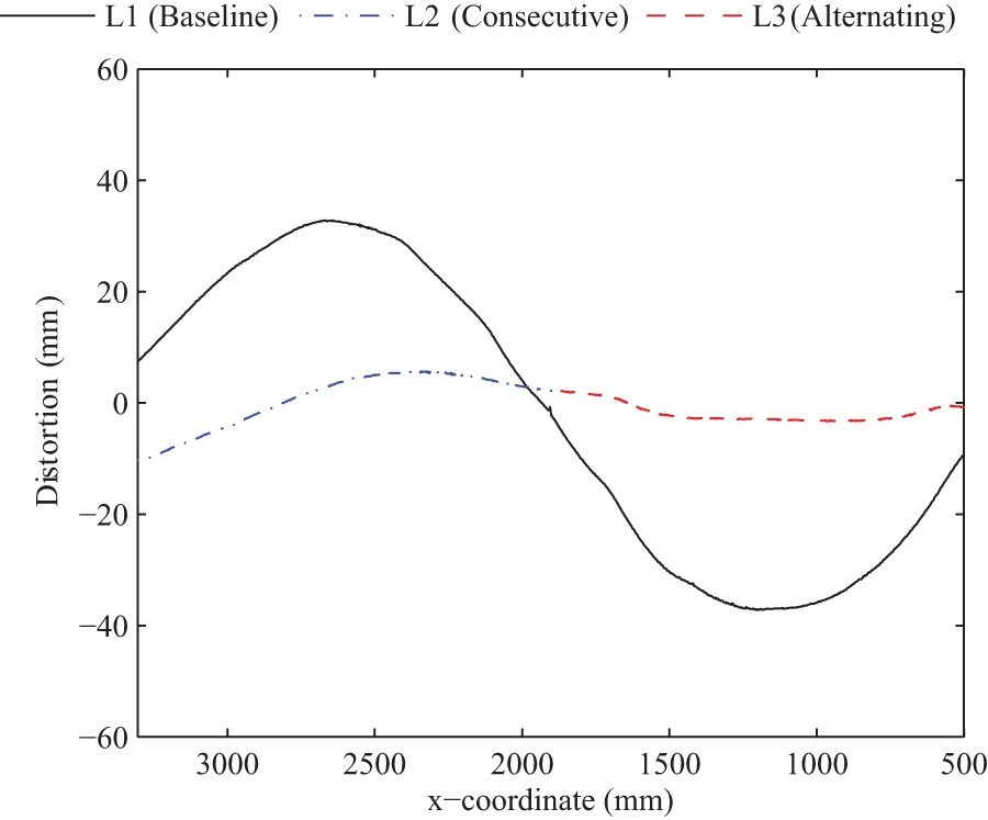
Comparison of distortion results before and after application of the distortion mitigation techniques on the targeted portion of the substrate.
Distortion results for the large part.
The application of the distortion mitigation strategies on the large part yielded similar results as are found from the small models. The small model intended to represent a large workpiece, predicted a percent distortion mitigation of 65% when adding sequential balancing layers, whereas the manufactured large part using sequential balancing layers yielded a 69% reduction in distortion. The use of alternating balancing layers on the small model yielded a distortion of 98% less than the baseline case compared with a 91% decrease seen on the large part compared with its baseline case.
The results also confirm that the use of balancing layers can be used to significantly mitigate distortion of large workpieces. Depositing the balancing layers sequentially after the deposition has been completed can be done to save processing time; however, the greatest distortion mitigation was achieved when depositing a balancing layer after each build layer.
Conclusion
Several distortion mitigation strategies for AM parts have been presented to allow for a significant reduction in the longitudinal bending of a workpiece. The approaches involve using heating to straighten a substrate or depositing additional material to balance the bending moment about the neutral axis of the workpiece. The distortion mitigation strategies are well suited for large parts, as they do not require any modifications to the AM system and do not require the impractical heating of the entire substrate to limit thermal gradients.
The effectiveness of the strategies is demonstrated on a small FE model. This allows for the lengthy computation time associated with simulating large parts to be avoided. The small models show that adding additional material is a superior mitigation technique compared with applying only heating; thus, the strategy is applied to the manufacture of large parts.
The distortion results of the large parts indicate that applying a balancing layer after each build layer yields favorable results when compared with depositing all balancing layers sequentially after the completion of the build layers and is capable of eliminating nearly all bending distortion. This consequence is in agreement with the prediction from the small models. The percent reduction in distortion on the large parts is found to be in close agreement with that calculated in the simulations. This shows that if the proper distortion mode is identified, a small model can be used to study distortion accumulation trends when applying different mitigation strategies and used to make decisions pertaining to a larger part. It is suggested that when designing a build plan, an effort should be made to deposit roughly equal volume of material on each side of the substrate in order to minimize substrate distortion.
Footnotes
Appendix 1
Declaration of conflicting interests
Any opinions, findings, and conclusions or recommendations expressed in this material are those of the authors and do not necessarily reflect the views of the Department of Defense or the US Government. Distribution Statement A: Approved for Public Release, Distribution Unlimited.
Funding
The author(s) disclosed receipt of the following financial support for the research, authorship, and/or publication of this article: This work was sponsored by a subcontract from Sciaky, Inc. and funded by AFRL SBIR #FA8650-11-C-5165 and was partially supported by the Open Manufacturing program of the Defense Advanced Research Projects Agency and the Office of Naval Research through Grant N00014-12-1-0840.