
Abstract
For semi-closed-loop computer numerical control machine tool, the pitch error of screw caused by thermal expansion can deteriorate the positioning accuracy of ball screw feed drive system. This study presents different prediction models for positioning error of ball screw feed drive system based on the mounting condition, where the total error is separated into geometric error and thermal error. The coefficients in the model are identified using the multiple linear regression method. The prediction model is validated and the error compensation is also done for the X axis of a three-axis computer numerical control milling machine. The test results show that the model developed can well predict the thermal error under any given temperature as well as position during the temperature rising process of ball screw, and it can greatly improve the system positioning accuracy through compensation.
Keywords
Introduction
Ball screw feeding system with semi-closed-loop numerical control (NC) is widely used in computer numerical control (CNC) machine tools because of its high positioning accuracy, transmission efficiency as well as long life. During the continuous rotation of ball screw, the bearings and nut produce a lot of heat due to friction, causing a temperature rise and then leading to thermal error for screw. This would finally deteriorate the positioning accuracy of feed system. Therefore, thermal error of ball screw has been popularly concerned to improve the positioning accuracy of machine tool. Weck et al., 1 Postlethwaite et al., 2 Ramesh et al. 3 and Mayr et al. 4 made a complete review on thermal issues in machine tool, certainly including linear axes.
The important issue in ball screw feed system due to heat is to estimate the thermal/temperature changes and the deformation. Theoretical modeling and numerical simulation are the frequent methods to do it. Wu and Kung, 5 Gleich 6 and Ming and Jiang 7 modeled the thermal behavior of the ball screw feeding system by finite element method to analyze the temperature distribution and the deformation on the ball screw shaft. Yun et al. 8 developed two thermal behavior models for ball screw and guide way separately to estimate the position errors of the feed drive system; the modified lumped capacitance method and genius education algorithm are used for the ball screw and the finite element method for the guide way. Yang et al. 9 employed the thermal structure finite element method to simulate the transient thermal deformation and temperature field of a jig-boring machine equipped with a dual-drive servo feed system at different feed rates. Ahn and Chung 10 and Shi et al. 11 yet mathematically calculated the thermal expansion of screw shaft in the axial direction based on the theory of heat generation and transfer. Although the relations for losses due to load and friction in the lubricating medium can be found in ball screw manufacturer catalogs, the modeling of heat transfer is rather difficult. Besides those numerical methods above, various experimental testing are also used. Huang 12 measured three thermal sources in ball screw feeding system by thermocouple and established a multiple regression model to compensate the thermal error. Heisel et al. 13 employed infrared thermography to measure the temperature distribution in the components of ball screw drive and then present a method to calculate the thermally induced positioning errors by a transformation between the three-dimensional (3D) object space and the two-dimensional (2D) image space. Wu and Kung 14 measured the thermal errors of a double-column machining center with capacitance probes in different combinations of spindle and feed system operation and achieved a 90% reduction in thermal errors after compensation. Horejs et al. 15 used both resistance thermometers and infrared camera to measure the temperature increases at points and profile of the ball screw and then also to calculate the positioning errors of the ball screw feed drives in machine tools.
The above research provided good solutions for the temperature field distribution and thermal error prediction of the ball screw feeding system. It is well known that the thermal changes in the length of the screw mainly depend on the factor, such as the type and dimensions of the screw, the nut and the bearings, the external load, the rotational speed, the work cycle and the heat transfer conditions. All of these factors vary greatly for different machine tools, so it is a hard task to establish a universal compensation model of thermal error for different ball screw feed systems. However, differing from other factors with various cases, the mounting of ball screw determining its form of thermal deformation is widely used by only three types in engineering. It is also seldom addressed in the published literature. Therefore, in this research, we proposed different prediction models for positioning error of ball screw feed drive system based on the mounting condition and established the relationship between position, temperature and positioning error by a multiple linear regression method.
Modeling method for positioning error of ball screw feed drive system
The deformation of ball screw deduced by heat mainly depends on its mounting method, which have the following three forms:
“Fixed-free.” The screw is fixed on one end and free on the other end, as shown in Figure 1. The bearing on the fixed end bears both radial and axial constraints. This form is usually suitable for short screws.
“Fixed-supported.” The screw is fixed on one end and supported on the other end. The bearing on the supported end only bears radial constraints and can still float small in the axial direction. This form is most widely used, especially in the medium and small CNC machine tools and machining centers.
“Fixed-fixed.” Both ends of the screw are fixed. This form can improve the bearing rigidity by forcing preload on the ball screw and is generally applied in large or high accuracy machine tools.
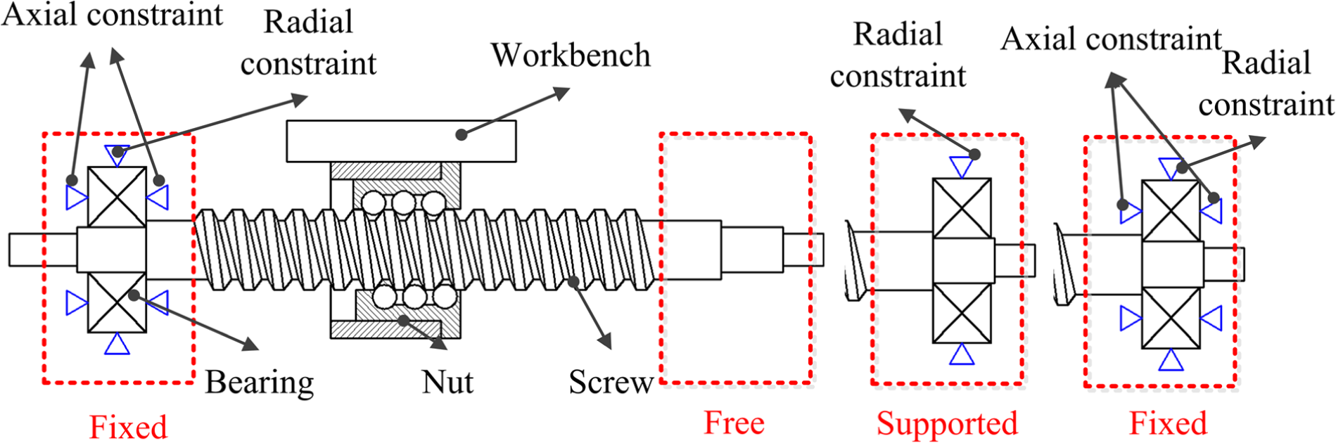
Three mounting methods of ball screw.
Based on three mounting forms of ball screw, the positioning error prediction models are deduced respectively as follows.
“Fixed-free” form
Using the “fixed-free” form, the heated screw expands to the free end. From fixed end to free end, the thermal elongation of the screw is continuously increasing, and theoretically, the thermal error curve is a straight line with different slopes at various temperatures. Compared with thermal error, the initial geometric error of screw is relatively stable under normal conditions. As a result, the positioning error of ball screw feeding system can be separated as plotted in Figure 2. The positioning error is fitted into a straight line, where the fitting line represents thermal error and the residual error stands for geometric error and system error (as referred to initial geometric error). Therefore, in the “fixed-free” form, the prediction model for positioning error of ball screw can be expressed as
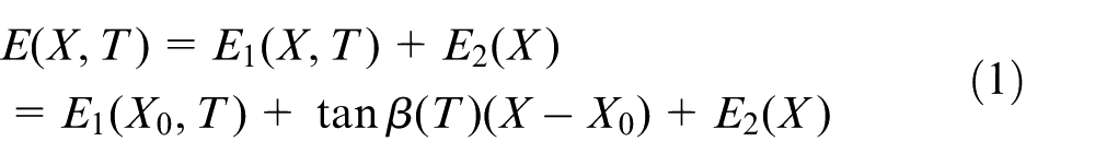
where E, E1 and E2 are the positioning error, thermal error and initial geometric error of the feeding system, respectively. T and X are the temperature and position of the worktable, and X0 is the reference position. The coefficient tan β is the slope of fitting line representing the compensation at temperature T.
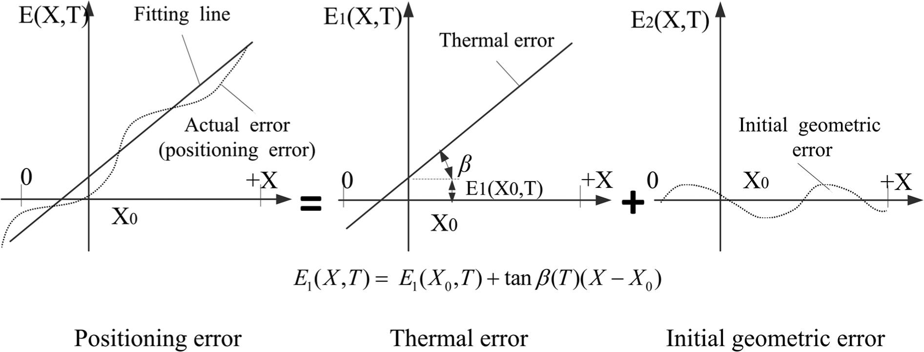
Separation method of positioning error of screw in “fixed-free” form and “fixed-supported” form.
“Fixed-supported” form
In the “fixed-supported” form, the supported end of the screw bears only radial constraints, and the direction of elongation is toward the supported end. Consequently, the trend of the thermal elongation is similar to the “fixed-free” form, and the modeling method of the positioning error is the same as that in last section.
“Fixed-fixed” form
In the “fixed-fixed” form, both ends of the screw are fixed, and the theoretical thermal error curve is a parabola. By fitting the positioning error using quadratic curve, the thermal error and the original geometric error of the feed system can be obtained as shown in Figure 3, so the positioning error prediction model of ball screw is given by
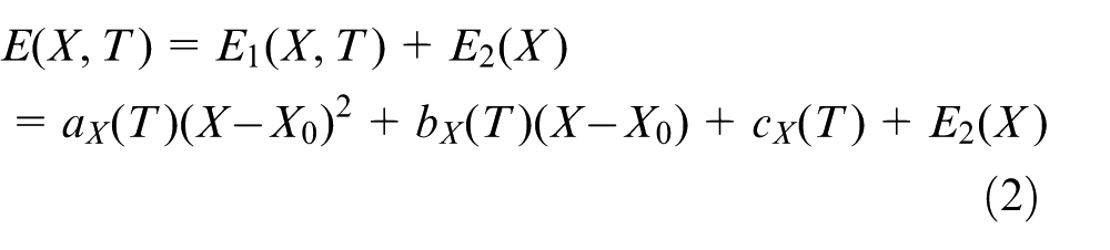
where ax, bx and cx are the coefficients of quadratic curve.
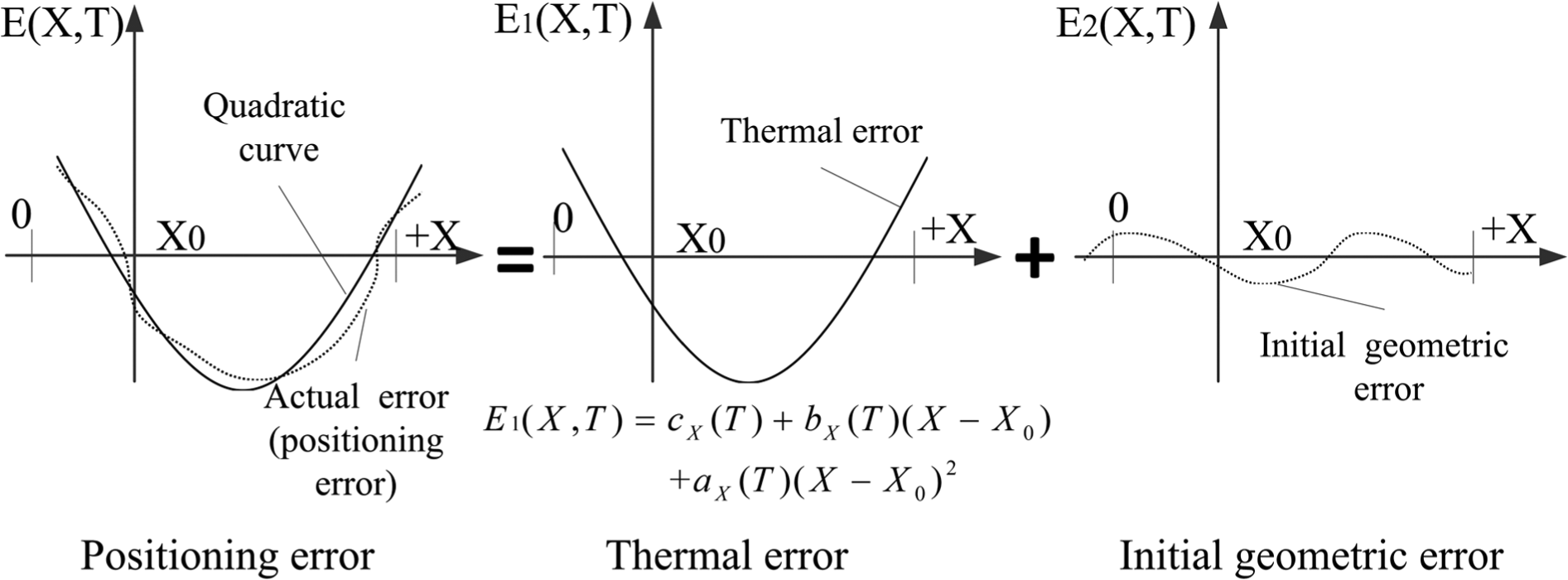
Separation method of positioning error of screw in “fixed-fixed” form.
Positioning error prediction model
Experimental scheme
The X axis of a typical three-axis CNC vertical milling machine was employed to test the positioning error, where the screw is both fixed on two ends. Three temperature sensors (model: SBWZ-T) were installed on heat source positions including the front bearing, screw nut and rear bearing, and the reading were recorded as T1, T2 and T3. Moreover, four more sensors were fixed around the screw and the average value (T4) was taken as the environment temperature.
A laser interferometer (model: Renishaw XL-80) was used to measure the positioning error of the feed system. The measured travel of X axis is set to 500 mm with an interval of 50 mm and X = 0 is selected as the reference point. First, measure the position deviation of the X axis under the initial state and record the values of temperature sensors. Second, drive the X axis to run repeatedly for 0.5, 1, 2, 3, 5, 7 and 9 h at a feed speed of 5 m/min to heat the screw parts and then measure the position deviation of the X axis, respectively; the temperatures of seven sensors are recorded simultaneously.
Figure 4 shows the measured position deviation of the X axis at different periods. It can be clearly seen that each curve behaves the same variation, but with the increase in the running hours, the overall change of the position deviation is getting bigger. After reaching the thermal equilibrium state (about 4 h later), the change gradually slows down. Every deviation curve is presented as a parabola, which is consistent with the theoretical analysis.
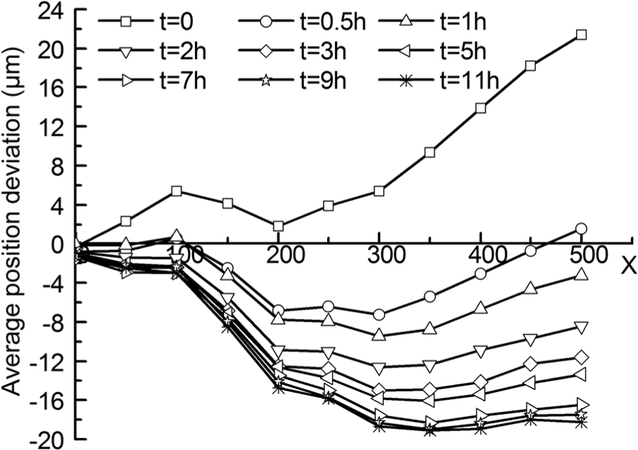
Average position deviation of different time.
Multiple linear regression of model
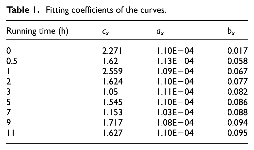
According to equation (2), the nine curves in Figure 4 can be fitted into quadratic curves and their coefficients are listed in Table 1.
Fitting coefficients of the curves.
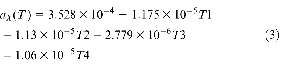
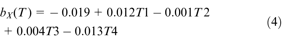
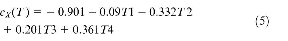
Using multiple linear regression method, the relationship between coefficients and temperatures (T1–T4) is identified as equations (3–5)
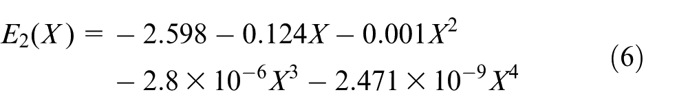
Based on the fitting data in Table 1 and measured data, we can easily get the residual error of curves at each measurement point and then take the average at each measurement point as the initial geometric error, which can also be fitted to equation (6)
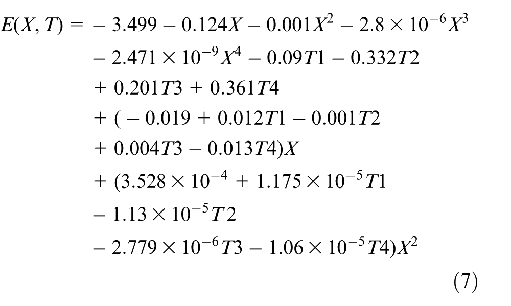
To sum up, the positioning error prediction model can be described as shown in equation (7)
Experimental verification and application of the prediction model
The initial environment temperature T4 was set to 21.6 °C by air conditioner. The X axis was driven to run for 1/6, 1/2, 1, 2, 3 and 4 h with a feed rate of 5 m/min, and the values of temperature sensors were also recorded. At each time interval, the position deviation of the feed system was measured by the laser interferometer in the following three cases:
Close the function of pitch error compensation in NC system, that is, no compensation;
Open the function of pitch error compensation, but the compensation value of each measurement point is a constant based on the error measured at initial temperature;
Open the function of pitch error compensation, and the compensation value of each measurement point is determined by the prediction model equation (7).
In the latter two cases, the error compensation includes both thermal error and geometric error. Through the three strategies above, the positioning accuracy of the X axis of machine tool is plotted in Figure 5. Compared with no compensation and constant compensation, prediction model compensation reaches the best positioning accuracy during the different work hours, which indicates that the accuracy of prediction model is well acceptable.
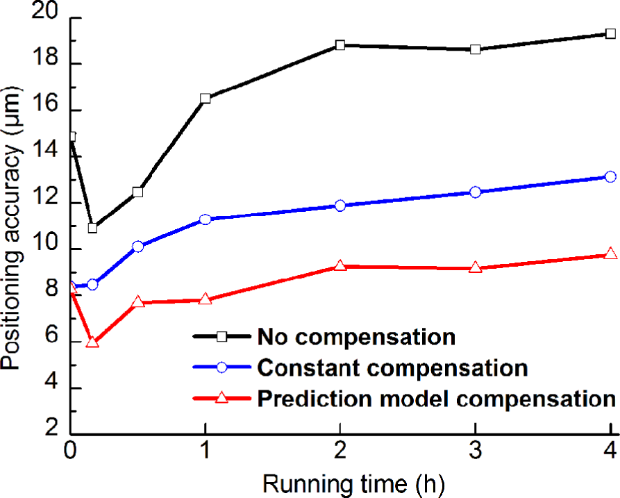
Comparison of positioning accuracy.
Conclusion
In this study, three different prediction models for positioning error of ball screw feed drive system were developed according to the mounting condition of ball screw, which can well describe the screw deformation. Geometric error and thermal error were both separated based on the deformation forms. Before reaching the heat equilibrium, the thermal error varies with temperature and position. The error was modeled using the multiple linear regression method. The prediction model is validated and the error compensation is also done for the X axis of a three-axis CNC milling machine. The result shows that this method can greatly improve the system positioning accuracy after compensation.
Footnotes
Declaration of conflicting interests
The author(s) declared no potential conflicts of interest with respect to the research, authorship and/or publication of this article.
Funding
The author(s) disclosed receipt of the following financial support for the research, authorship, and/or publication of this article: This work was financially supported by the National Science and Technology Major Project of China (No. 2014ZX04014-021).