
Abstract
A proper plastic behavioral model is required to simulate metal cutting. Here, we model the plastic behavior of AISI 316LN stainless steel during face milling. We used a numerical approach to derive a plasticity model appropriate for machining; a two-dimensional cutting force prediction and a genetic algorithm were conducted for that. The force prediction was performed considering a geometrical relationship between the work material and cutting tool. We used the Johnson-Cook (JC) constitutive material model, and initial model parameters were obtained via tension testing at low strain rates (0.001–1 s−1). The genetic algorithm optimized the model parameters; the predictive accuracy with respect to cutting force was high in the model with optimized parameters. We used the optimized JC model for finite element analysis and simulated face milling with a round insert. We measured the cutting forces to validate our modeling approach; the simulated and measured principal forces were in good agreement (error rate ≤ 3.9% under all machining conditions). Our model improved the accuracy of plastic behavior prediction by 93.0% versus the original model. The high accuracy was retained even when the machining environment changed.
Introduction
AISI 316LN, a chromium-containing stainless steel with good corrosion resistance 1 and excellent mechanical properties, 2 finds applications in the chemical, nuclear energy, and petrochemical industries. However, AISI 316LN is considered difficult to machine; the work-hardening rate is high and the thermal conductivity is low. 1 The high nickel content increases the work-hardening rate because an austenitic structure is formed.3–5 During machining, heat generated by plastic deformation is difficult to dissipate because the poor thermal conductivity means that the cutting temperature rises. This increases tool wear, which reduces tool life and productivity. The flow stress at the shear zone is important in terms of machinability. The flow stress affects both the cutting force and temperature, in turn influencing tool life and product quality. Therefore, earlier works used numerical methods to study the machining mechanism based on flow stress.6–8 Metal plastic behaviors have been evaluated by deriving material constitutive models.9–12 The Johnson-Cook (JC), Zerilli-Armstrong (ZA), Bodner-Partom (BP), and Khan-Huang (KH) models are typical plasticity models that can be used to analyze materials with different properties. 13 The JC model is suitable for analysis of metals subjected to large strains and high temperatures. The model optimally analyzes materials exhibiting positive relationships between the strain and work-hardening rates. Then, the JC model is applicable to aluminum and steel, both of which exhibit small variations in work-hardening rates. The ZA model has been used to analyze the materials of various structures (FCC, BCC, and HCP), but cannot derive relationships of the work-hardening rate with the strain rate and temperature. The BP and KH models can handle the work-hardening behaviors of metals at large strain rates, but it is difficult to model the effects of temperature. During AISI 316LN machining, flow stress is affected by both the high cutting temperature and work-hardening. Therefore, the JC model is appropriate for exploring the plastic behavior of AISI 316LN.
Plasticity model parameters are derived by fundamental material testing. Machining is commonly performed under high strain rates (103–106 s−1), and thus at high temperature; material tests have been conducted under such conditions. Lee et al. 14 derived the JC model parameters of a Ti-6Al-4V alloy using a split Hopkinson pressure bar technique under a constant strain of 2 × 10³ s−1 and temperatures of 700–1100°C. Kobayashi et al. 15 analyzed the plastic behavior of the Inconel 718 alloy over the strain range 0.01 to 3000 s−1 using a split torsional Hopkinson bar and a quasi-static torsion machine. Chandrasekaran et al. 16 performed fundamental machining of, and split Hopkinson bar tests on, AISI 316 steel. However, the strain rates of machining and material tests are still different, and it is difficult to precisely simulate plastic deformation during machining using only material test-based parameters. Thus, the model must be optimized for machining. Daoud et al. 17 performed orthogonal cutting to determine plasticity model parameters using a response surface methodology-based inverse approach. Rahman et al. 18 modeled the flow stress by considering grain size and chip thickness during machining. Ning et al. 19 determined JC model constants of titanium material based on chip formation. The plastic behavior derived via fundamental machining was relatively accurate. However, tool geometry, work material shape, and machining conditions can all affect plastic behavior, and accuracy may be reduced if the machining environment changes. Therefore, plasticity models must be optimized based on numerical studies of the machining mechanism, and the optimization approach should be verified when the machining environment changes.
Finite element models (FEMs) have been used to analyze machining processes and optimize machining conditions.20–23 In a FEM, a plasticity model is used to represent flow stress; many authors have emphasized the importance of using a reliable plasticity model. Chen et al. 20 performed finite element analysis (FEA) using a JC model. Jomaa et al. 21 used the JC approach to develop a modified damage model simulating high-speed machining of an AA7075-T651 alloy. Pan et al. 22 simulated residual stress for Ti-6Al-4V machining by applying the JC model.
In this study, we modeled the plastic behavior of AISI 316LN during machining. JC model parameters were initially obtained via tension testing. A model predicting orthogonal cutting force was derived and simulated using the JC parameters; the relationship between the cutting force and the JC model was numerically analyzed. Next, the plasticity model was optimized using a genetic algorithm, in which the objective function was the accuracy of the force prediction; the approach considered the machining mechanism during the plastic deformation with high strain rates. We used the optimized plasticity model to simulate face milling performed with a round-edge tool. Three-dimensional FEA was used to predict the cutting forces under various machining conditions. We validated our approach by measuring the cutting forces during milling and assessed the reliability of our optimized model of plastic behavior.
The material model
We subjected AISI 316LN to tension testing to derive the JC parameters A, B, n, C, and m. The JC model features three terms; the first term includes A, B, and n; the second and third terms include C and m, respectively (equation (1)). The first term refers to plastic deformation at room temperature, and the second and third terms represent the effects of strain rate and temperature, respectively 9 :

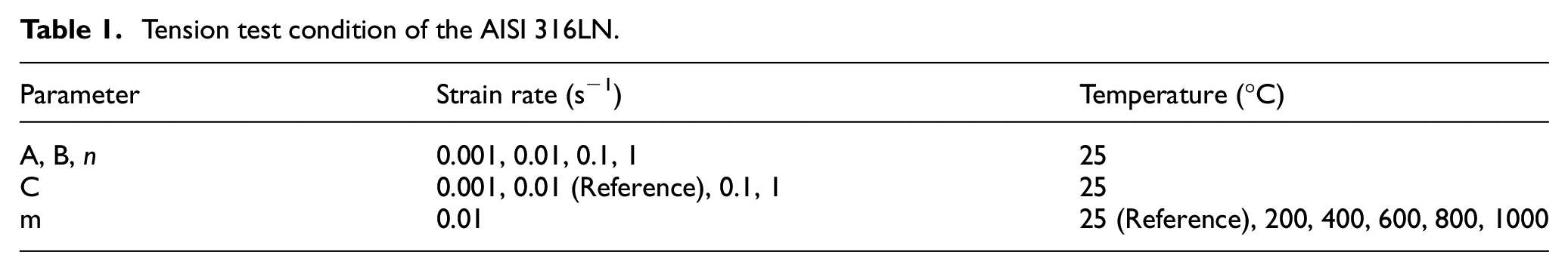
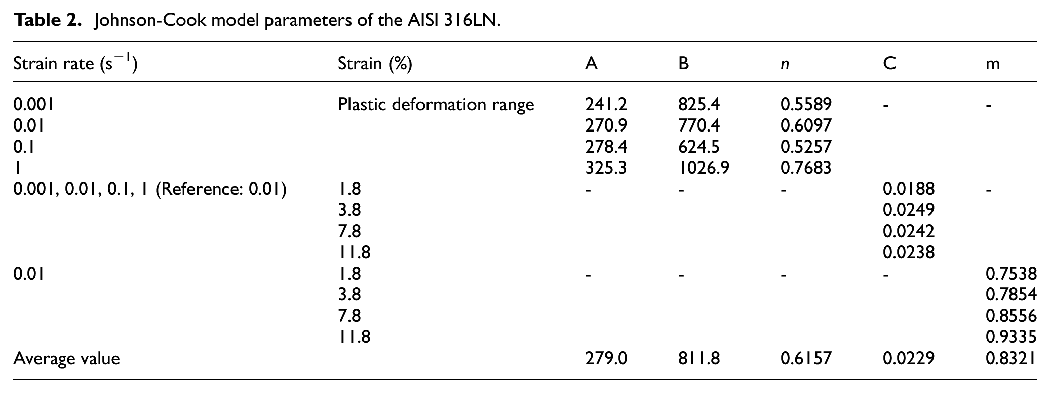
where σ is the flow stress, A is the yield stress, B is the strain-hardening coefficient, n is the strain-hardening exponent, C is the strain rate coefficient, m is the thermal coefficient, and ε is the plastic strain. We used a modified ASTM E8 specimen. Since the cutting temperature is high, a wide range of ambient temperatures (25–1000°C) were explored. Low strains (0.001–1 s−1) were applied using a tension tester (Type 5982; Instron). The experimental conditions and results are summarized in Table 1 and Figure 1. The plastic flow stress was more affected by the temperature than the strain rate; the stress was proportional and inversely proportional to the strain rate and temperature, respectively. The JC model constants were derived by reference to the correlations listed in Table 2. Four values were obtained for each parameter under various testing conditions. In this study, the strain rates are relatively low as compared to machining condition. The nucleation and recrystallization of grains occur during metal plastic deformation. Since the lower strain rate provides longer time for the recrystallization with dislocation annihilation, the low strain rates can cause small plastic stress, which reduces the cutting force. 24 Thus, the model optimization was required, considering machining condition (section “Machining-based plastic behavior”).
Tension test condition of the AISI 316LN.
Johnson-Cook model parameters of the AISI 316LN.
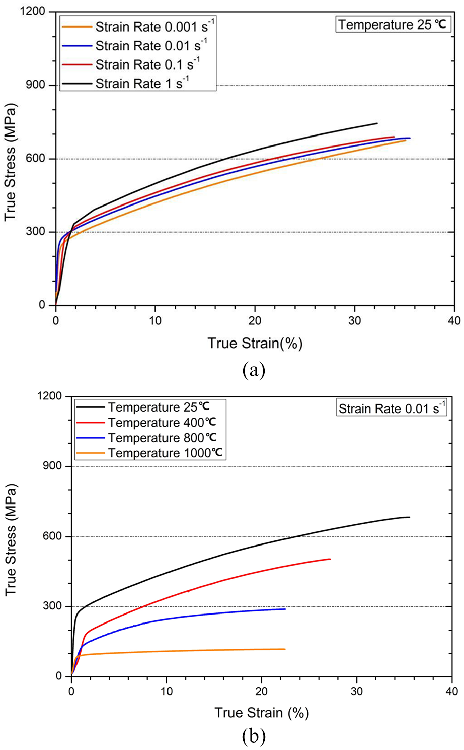
Flow stress-strain curves under: (a) various strain rates, and (b) temperatures.
Machining-based plastic behavior
We optimized our model of AISI 316LN plastic behavior. The plastic deformation of work material was numerically analyzed based on two-dimensional machining (orthogonal cutting). Then, the plastic behavior was optimized by a genetic algorithm-based modeling. The proposed methodology is described in Figure 2.
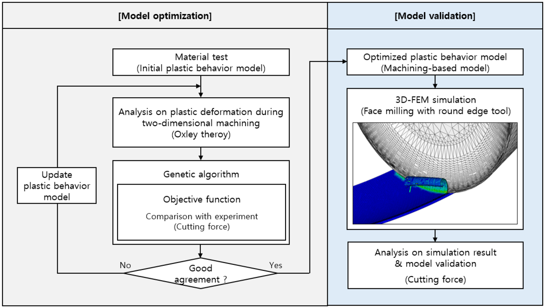
Flow chart for modeling the plastic behavior of AISI 316LN stainless steel during machining.
Genetic algorithm-based modeling
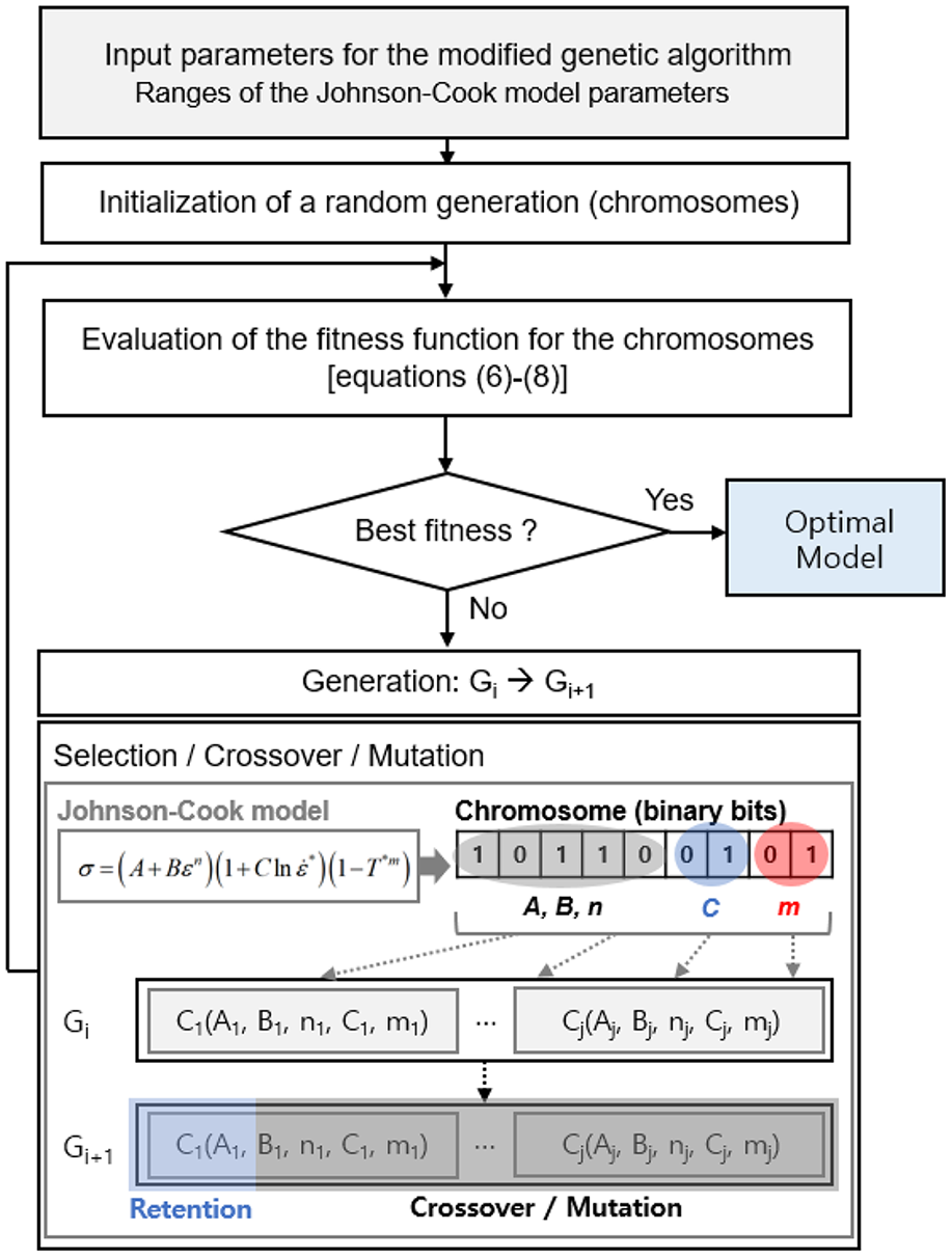
Genetic algorithms efficiently optimize processes in an evolutionary manner25–27 and find many applications.28–30 A flow chart of the genetic algorithm for the JC model is shown in Figure 3. The initial state features a group of random chromosomes representing combinations of JC parameters. The chromosomes consist of binary bits; an objective function is used to analyze their fitness in successive generations. The formulas are shown below in equations (2)–(8). The chromosomes are defined using the JC parameters, and the range of parameter combination depended on the material test-based model parameters. Cutting force is an important machining output. During metal cutting, the material is plastically deformed under large strains, generating a cutting force; the cutting force is directly representative of plastic stress. Therefore, the accuracy of the cutting force predictions in the cutting and thrust directions was used as the objective function. Cutting forces were simulated using the JC model parameters in every generation.


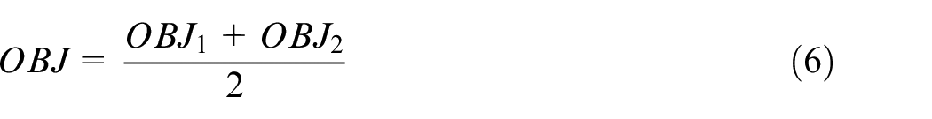
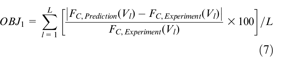
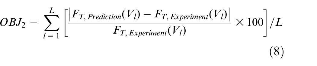
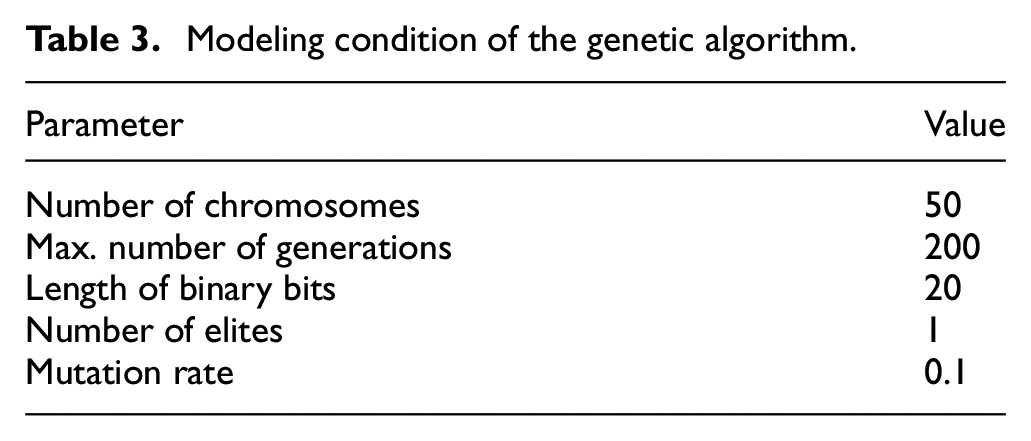
where x represents the JC parameters (A, B, n, C, and m), dx and Rx are the ranges of x used in the genetic algorithm, chromosomej is the jth chromosome, Cj is the jth combination of the JC parameters, OBJ is the objective function, Vl is the lth cutting speed, L is the number of applied cutting speeds, FC,Prediction and FC,Experiment are the predicted and experimental cutting forces, respectively, FT,Prediction and FT,Experiment are the predicted and experimental thrust forces, respectively, and Gi is the ith generation of the genetic algorithm. As the generations progressed, three principal operators (retention, crossover, and mutation) were applied and a chromosome minimizing the objective function was thus derived. The parameters used are summarized in Table 3.
Modeling condition of the genetic algorithm.
Flow chart of the genetic algorithm for the Johnson-Cook (JC) parameters.
Prediction of cutting force
It is proper to analyze the plastic behavior with strain rates of machining. However, a machining test-based derivation cannot ignore the influence of surrounding environment, including tool geometry. Thus, we predicted the plastic stress numerically using MATLAB. The cutting force was simulated during two-dimensional machining, orthogonal cutting, based on Oxley theory; the Oxley model predicts cutting force using a slip-line method. 31 The plastic stress was computed using the material properties and tool geometry as input parameters. The geometric relationship between the work material and cutting tool was considered in equations (9)–(11). The geometrical parameters, that include slip-line field angle, shear angle, chip thickness, and tool rake angle, were adopted.
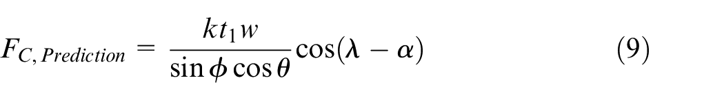
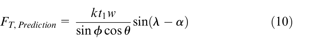
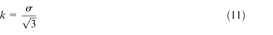
where k is the shear stress at the shear zone, t1 is the undeformed chip thickness, w is the cutting width, ф is the shear angle, θ is the slip-line field angle, λ is the friction angle, and α is the rake angle of the cutting tool. The cutting and thrust forces at the shear zone were predicted numerically. Stresses at the shear zone and tool-chip interface were computed with various shear angles based on the JC model; strain rate and temperature values depended on the cutting speed. When the computed stresses are in equilibrium, the corresponding shear angle and plastic stresses were determined. Then, the cutting forces were calculated by the sectional area of shear zone. The predictions were used to generate an objective function for the genetic algorithm. Since the machining mechanism was studied numerically, the objective function may consider the plastic deformation only, without other geometrical effects.
Orthogonal cutting experiment
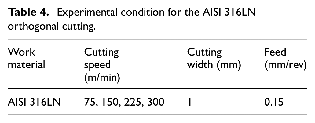
We cut AISI 316LN stainless steel orthogonally and measured the cutting forces. The cutting tool rotated at a constant speed. The experimental conditions and setup are described in Table 4 and Figure 4. A CNC lathe (TSL-6; S&T) and force dynamometer (9257B; Kistler) were used, and a disc-shaped specimen (width, 1 mm) was assessed. As the material is sensitive to temperature, various cutting speeds (75, 150, 225, and 300 m/min) were applied at a feed rate of 0.15 mm/rev. We used a sharp carbide cutting tool (N151.2-A094-25-3F; SANDVIK). During machining, cutting and thrust forces were measured at 1000 Hz. Since the cutting force vibrates according to the dynamic properties of the machine center, the output force was obtained by averaging the measured data.
Experimental condition for the AISI 316LN orthogonal cutting.
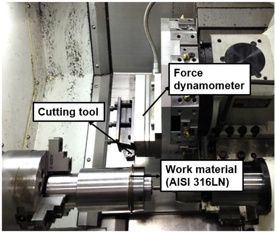
Experimental setup for orthogonal cutting of AISI 316LN stainless steel.
Finite element model
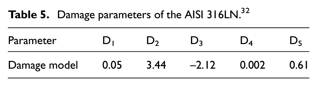
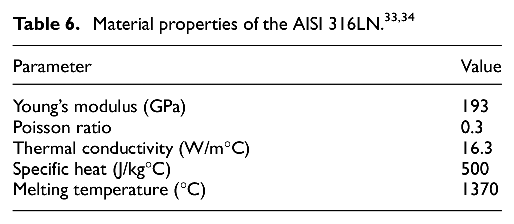
We used commercial ABAQUS-3D software to simulate face milling with a round insert. The model focused on the machining area (Figure 5) and included some of the work material close to that area. A thin structure for work material was created based on the path of cutting tool to improve the simulation efficiency. Since the thermal conductivity of work material is low, it was assumed that the created structure has less influence on the temperature and stress inside the material. We used a carbide cutting tool to machine AISI 316LN, which exhibited plastic behavior; the cutting tool was rigid. The work material was modeled as a thermally coupled brick with eight nodes and trilinear displacement and temperature (C3D8T) elements (227,000 elements in total). The initial temperature was 25°C and the convective heat coefficient at the material surface was 25 W/m2°C. The cutting tool rotated at a constant speed and the lower part of the work material was fixed. We used the JC damage model for chip formation; the damage model is adequate to simulate chip separation by eliminating mesh elements during machining of ductile metals (equation (12)):

Where εf is the plastic strain to fracture, and D1–5 are the damage parameters, which reflect the capacity to maintain plasticity. The damage parameters and material properties of AISI 316LN stainless steel are listed in Tables 5 and 6, along with those of previous reports.32–34
Damage parameters of the AISI 316LN. 32
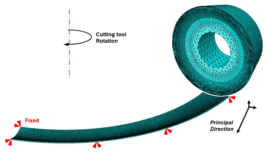
Finite element model of AISI 316LN stainless steel face milling.
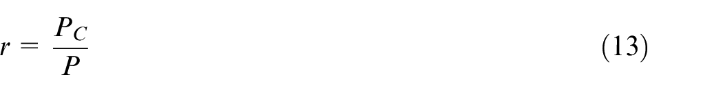
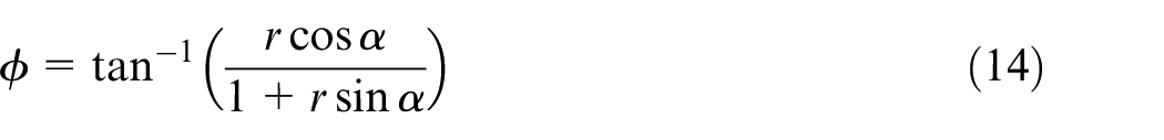
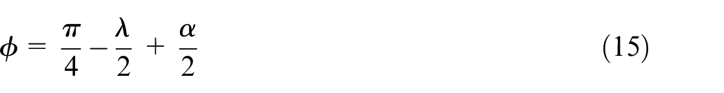
During machining, an adhesive friction occurs at tool-chip interface, which friction is determined by properties of work material and cooling condition. Vyas et al. 35 reported that the chip morphology represents the friction characteristics (equation (13)–(16)). In this study, a chip analysis was performed to derive the friction coefficient, after collecting chips which were generated by the orthogonal cutting experiment in different cutting speeds. The computed coefficients can be summarized in Table 7.

Friction coefficients at tool-chip interface.
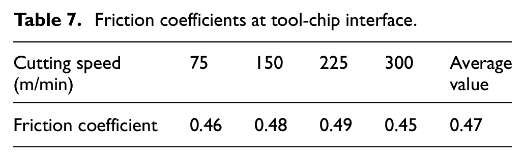
where r is a chip ratio, PC is a distance between teeth of chip, and P is a chip height., An average value of the derived friction coefficients was implemented in the face milling simulation because the influence of cutting speed on friction was not significant. The optimized JC model parameters were used to simulate the cutting force. The simulation was verified experimentally (section “Effects of the plasticity models on finite element analysis”).
Experimental setup
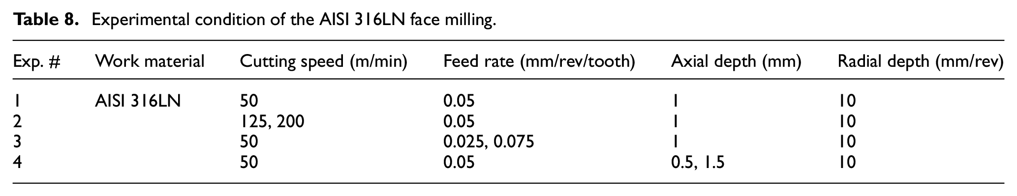
We used a C40U milling machine (HERMLE) to perform face milling (Figure 6), along with a cutting tool holder (R220.29-0050-05.6A; SECO) and a round carbide insert (RDHT10T3M0T-M05; SECO). AISI 316LN stainless steel was machined into a block-like specimen. Four types of experiments were performed (Table 8). A fundamental test was conducted using a cutting speed of 50 m/min, a feed of 0.05 mm/rev/tooth, and an axial depth of 1 mm. Next, the effects of cutting temperature and machining area were investigated under various cutting speeds, feed rates, and axial depths. The radial depth was set to 10 mm for down-milling. A force dynamometer attached to the work material measured cutting forces at 1000 Hz. The maximum value in a milling force profile was used as an output. The means and standard deviations of the force data were derived for five measurements obtained under each machining condition.
Experimental condition of the AISI 316LN face milling.
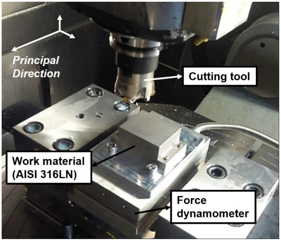
Experimental setup for AISI 316LN face milling.
Results and discussion
Derivation of the plastic behavioral model
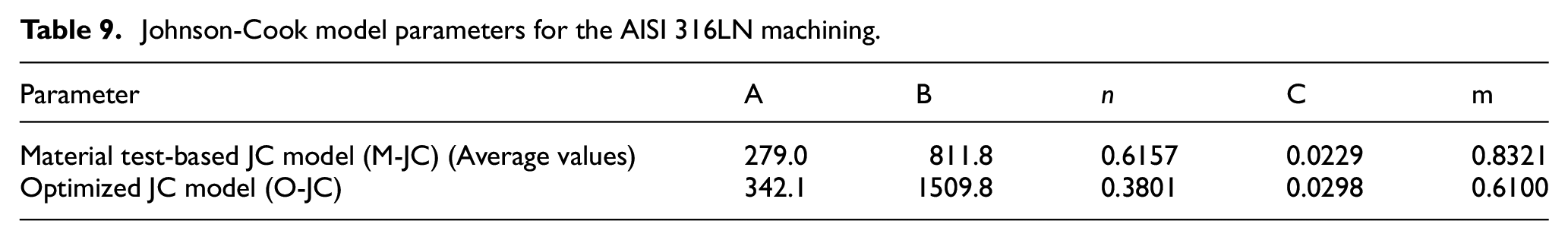
We used the cutting force predictive model and the genetic algorithm to optimize the JC model parameters; we aimed to model the plastic behavior evident during the machining of AISI 316LN stainless steel. The optimized model (O-JC) is summarized in Table 9; the average values of the material test-based JC model parameters (M-JC) are also shown. For the O-JC model, the value of parameter A (overall magnitude of plastic stress) was higher than that of the M-JC model. The strain rate coefficient, C, also increased, but the thermal coefficient, m, decreased. The B and n parameters, which reflect the influence of plastic strain, changed in opposite directions. To analyze the optimization approach, the plastic behaviors imparted by the M-JC and O-JC model parameters were studied under different strain rates and temperatures, as shown in Figure 7. The machining-based model, O-JC, greatly increased the plastic stress. As the B and C parameters increased, the variations in stress caused by the strain and strain rate both increased. Although the value of m decreased, the variation in stress induced by temperature also increased, given the overall increase in plastic behavior. Usually, constitutive material models consider the effects of strain rate and temperature independently. However, machining causes plastic stress in the shear zone, where both the strain rate and temperature increase simultaneously. When the temperature rises, the properties of the work material change; the influence of strain rate on plastic stress varies by temperature. In this study, it appears that differences in the mechanisms of material testing and machining was attributable to the difference between the two plastic behaviors. Moreover, the recrystallization occurs during the longer time at the low strain rate, which can reduce the plastic stress. This mechanism can induce the difference because the M-JC model was derived at only low strain rates.
Johnson-Cook model parameters for the AISI 316LN machining.
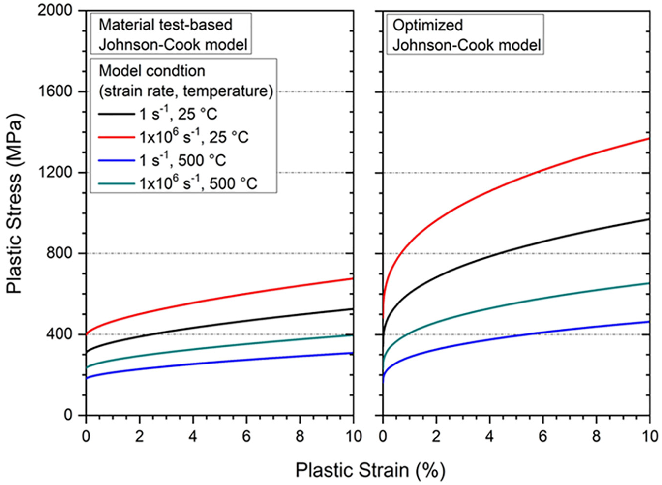
Plastic behaviors of AISI 316LN stainless steel predicted using the M-JC model and the O-JC model.
The predicted and measured orthogonal cutting forces were compared during derivation of the plasticity model (Figure 8). The predicted cutting force was based on the O-JC model. The forces were in good agreement (error rate ≤ 16.0%). As the cutting speed increased, the measured cutting force tended to decrease; high cutting speed increases the cutting temperature and weakens the work material. The predicted result well reflected the trend of experimental data.
Comparison of the experimental and predicted orthogonal cutting forces.
Effects of the plasticity models on finite element analysis
The FEM simulation was performed using both plasticity models. The machining conditions are shown in Table 8 (Exp. #1). Stress was analyzed according to plastic deformation and chip formation (Figure 9). Although the same cutting condition was used, the stress was greater when the O-JC model was adopted. The result was the same as shown in Figure 7. The chip curvature was greater in the O-JC model. Chip curvature is usually proportional to thermal softening during machining. As shown in Figure 7, in the O-JC model, temperature affected plastic stress more so than in the M-JC model. Moreover, the difference in the effect of temperature increased as the plastic strain and strain rate increased. During machining, the work material was plastically deformed at large strain rates, and the effect of temperature in the O-JC model seemed to increase the chip curvature.
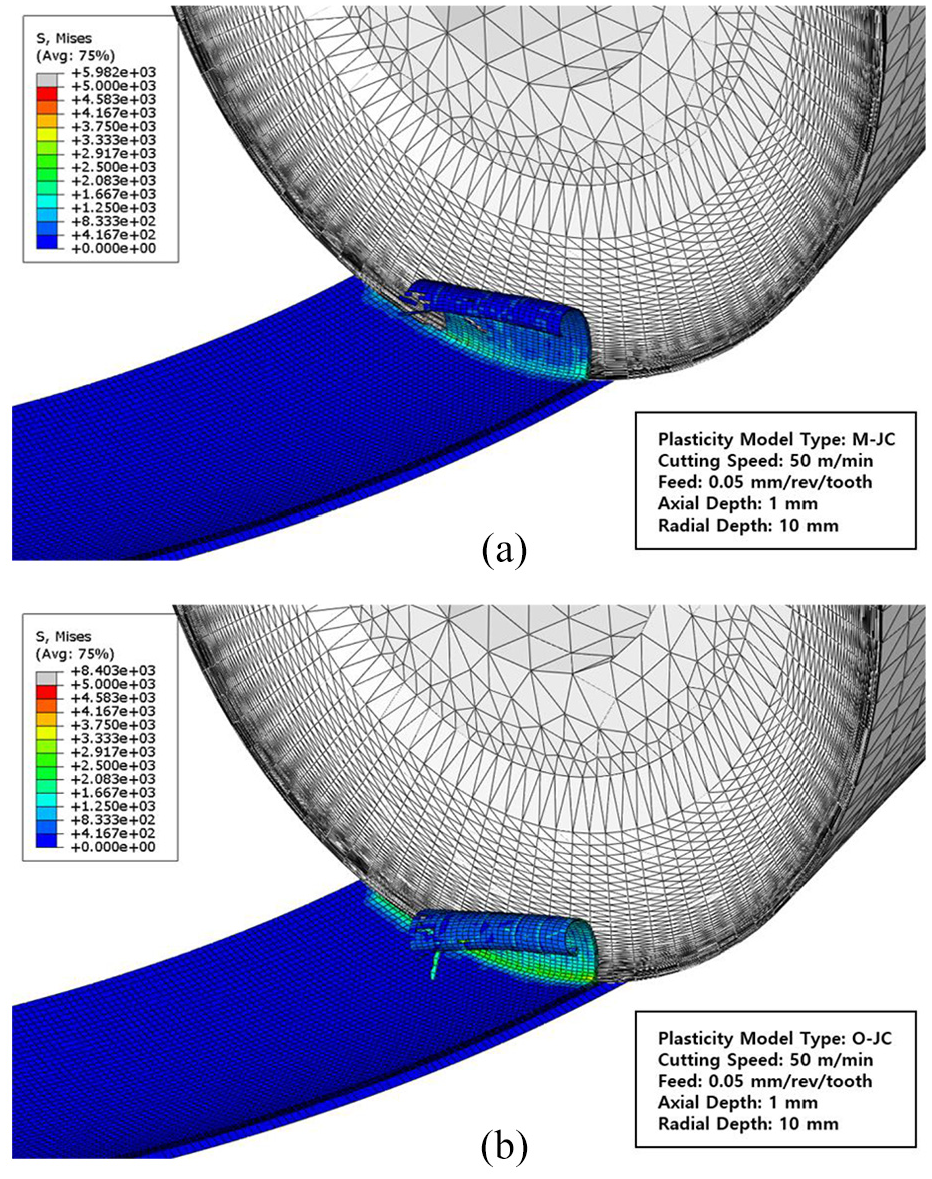
Plastic stress simulated during machining AISI 316LN stainless steel using: (a) the M-JC model, and (b) the O-JC model.
We quantified plastic stress in the two plasticity models, focusing on the shear zone. In the FEM model, a path line was drawn across the shear plane, and simulated Von-Mises stress was measured along this line. The stress profiles and a schematic diagram of the path line are shown in Figure 10. The maximum stress in both plasticity models occurred in the shear plane; stress decreased with distance from the shear plane. The difference between the two profiles was remarkable. In the O-JC model, the maximum stress was 54.2% higher compared to the M-JC model. Moreover, principal shear stress (S23) was also simulated at the plastic deformation zone; the simulation results were extracted along the path line. A magnitude of shear stress depends on the chip flow direction. The shear stresses of the two plasticity models were quantitatively compared in the same region, and the maximum value of O-JC model was 110.6% higher than that of M-JC model.
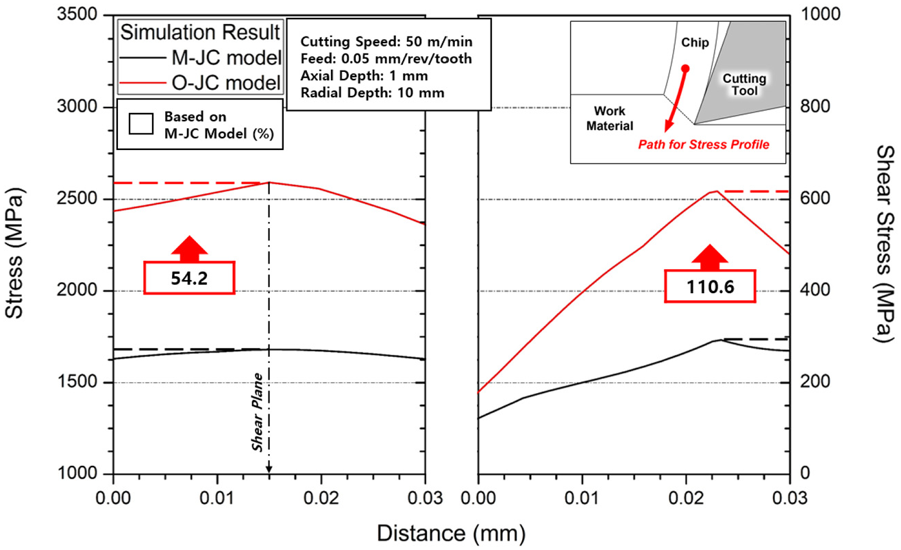
Simulated stress profiles across the shear plane.
Model validation
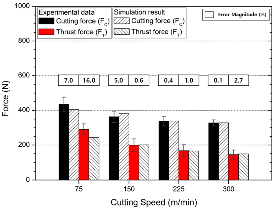
To verify our modeling approach, milling forces were simulated under various machining conditions using the O-JC model. The simulation results were compared to the experimental cutting forces measured by face milling. In the milling, the machining depth and cutting force vary by the tool rotation angle. During down-milling, the cutting force increases abruptly as the cutting tool contacts the work material, and the force profile gradually decreases with tool rotation. Since a high cutting force reduces machinability and product quality in general, we focused on the cutting force in the principal direction; the output was obtained from the maximum value of milling force profile. The predicted and measured cutting forces are compared in Figure 11. Data were collected under different cutting speeds, feed rates, and axial depths. As the cutting speed increased, the cutting force decreased. An elevated cutting temperature mechanically weakened the material. On the other hand, the cutting force was proportional to the feed rate and axial depth. The simulation well-captured the experimental trends; agreement was excellent (error rate ≤ 3.9%) under all machining conditions. The plasticity model was optimized for two-dimensional machining, but the validation was conducted during three-dimensional face milling. Our modeling approach was not affected by the machining environment due to the numerical model-based optimization.
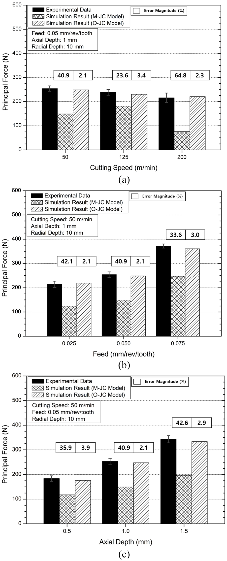
Comparison of experimental and simulated principal milling forces depending on: (a) the cutting speed, (b) feed rate, and (c) axial depth.
The principal milling forces were also simulated using the M-JC model and the prediction accuracy was compared between the O-JC and M-JC models. The simulation results are shown in Figure 11; the cutting forces simulated by the M-JC model were relatively low. Plastic stress analysis (see above) showed that the stress derived using the M-JC model was lower than that of the O-JC model; the same tendency was evident when the cutting forces were compared. The overall trends in the simulated cutting forces were similar to the experimental data. However, the M-JC model underestimated the milling forces and the validation showed high error rates. The average error rate was 40.5%, whereas that of the O-JC model was 2.8%. The simulation error was reduced by 93.0% when the O-JC model was used instead of the M-JC model. It is inappropriate to model machining based only on fundamental material testing; the proposed plastic behavioral modeling is required. The O-JC model well-represented the machining of AISI 316LN stainless steel.
Conclusion
We modeled the machining-based plastic behavior of AISI 316LN stainless steel. The modeling process analyzed the cutting force numerically and optimized the plastic behavior using a genetic algorithm. The derived plastic behavioral model was validated by the FEM simulation and the measurement on cutting forces. In summary:
- A JC model of AISI 316LN stainless steel was initially derived via fundamental tension testing under low strain rates. The parameters were optimized using the genetic algorithm and a model for predicting cutting force. The objective function was the accuracy of the predicted orthogonal cutting force. In the optimization, the O-JC model-based predictions were in reasonable agreement with the experimental data (error rate ≤ 16.0%).
- Our modeling approach increased the magnitude of plastic stress. When the O-JC model was used, the variation in plastic stress caused by changes in the strain rate and temperature were larger than in the M-JC model.
- We performed FEA of AISI 316LN stainless steel milling, followed by face milling, to measure the cutting forces and validate the optimized plastic behavioral model. The measured and simulated cutting forces were in excellent agreement (error rate ≤ 3.9%). Our modeling methodology is minimally dependent on the machining environment.
- The machining-based plasticity model, O-JC model, improved the FEM-based simulation accuracy of the AISI 316LN stainless steel machining. The average error between the simulated and measured milling forces was 93.0% lower in the O-JC versus M-JC model. Thus, our approach appropriately modeled plastic behavior during the machining of AISI 316LN stainless steel.
Footnotes
Appendix 1
Declaration of conflicting interests
The author(s) declared no potential conflicts of interest with respect to the research, authorship, and/or publication of this article.
Funding
The author(s) disclosed receipt of the following financial support for the research, authorship, and/or publication of this article: This research was supported by the field test of cryogenic machining in heavy duty cutting process funded by the Ministry of Trade, industry & Energy (MOTIE) of Korea (No. 20007235), Development of an on-site facility attached cryogenic machining integrated system funded by Korea Institute of Industrial Technology (Kitech EO-20-0009), and the National Research Foundation of Korea (NRF) funded by the Ministry of Science and ICT of Korea (No. 2018R1A2B3007806 and 2017R1A5A1015311).