
Abstract
Direct energy deposition has been established as one of the methods for additive manufacturing metallic parts. The combination of direct energy deposition capabilities with traditional machining centre capabilities has enabled over the past few years the creation of hybrid manufacturing cells that are able to additively manufacture and finish machine components under one platform. This article investigates the production of geometries using a hybrid, additive and subtractive approach. The parameters for depositing stainless steel 316L are initially investigated followed by an assessment of machinability of the additively manufactured material. Finally, the quality of the deposited and machined material was thoroughly examined with a series of destructive and non-destructive methods.
Introduction
Manufacturing industries are being challenged more than ever to reduce their environmental impact. The UK aviation industry has pledged to cut its net carbon emissions to zero by 2050, 1 and the UK government has committed to reaching net zero emissions by 2050 2 along with a ban on sales of combustion engine cars from 2035. 3 This has set a clear marker for the manufacturing sector, where rather than through economic drivers, social demands are calling for the efficient use of resources, improving processes in terms of their sustainability and waste. The only way to achieve this is through the adoption and implementation of new technologies, enabling highly efficient operations in terms of materials and energy to meet these new regulations and grant access to high value markets. 4
Additive manufacturing (AM) has revolutionised the way manufacturing of components is realised, rapidly developing as a viable manufacturing option across multiple industries. 4 AM uses a layer-by-layer approach to add and shape feedstock materials to form complex shapes,5–7 often not possible through traditional subtractive manufacture. This ability enables the deposition of near-net structures, reducing material waste and finish machining.4,8
The combination of AM capabilities with traditional machining on a single platform has the potential to maximise the benefit afforded by AM withoutre-fixturing and added transportation of the component. These hybrid manufacturing platforms combine machining and AM in the most efficient way taking advantage of the benefits of both processes to build, augment and repair components used in all industries.9–12
Directed energy deposition (DED) is a major subset of the currently available AM processes which uses a high-energy density heat source, such as a laser, electron beam or arc to create a melt pool into which metal powder or wire is injected.6,13 Blown powder DED is the most popular AM process for metallic parts in hybrid manufacturing. 9 This process enables the deposition of a material onto a substrate with high deposition rates while at the same time offering much lower levels of dilution than wire feed methods and more capability in terms of complex geometries. This is partly due to the fact that coaxially delivered systems offer the ability to produce uniform track size independent of travel direction, offering greater process capability and robustness. 14
Austenitic steels such as 316 are widely used in industry due to their high strength, ductility and corrosion resistance. 15 However, due to the feedstock used and the rapid cooling involved with the process, the microstructure of AM material varies greatly compared to conventional material and between different AM processes. 8
Wang et al. looked into the effect of processing parameters on microstructure and tensile properties of blown powder DED AM stainless steel. It was found that the microstructure varied greatly depending on the processing parameters and relative position in the build, with each location in the build subject to a complex thermal history due to the initial solidification and subsequent re-heating and cooling during each additional layer. This causes heterogeneous and anisotropic microstructures that differ from the traditional wrought material. 16
In order to avoid defects, robust parameters have to be produced for specific processes and powder types. Varying laser power, travel speed and powder feed rate determine the build quality and physical properties of the material.16–19 It was found by Zhang et al. that yield and tensile strength decreased when increasing laser power and decreasing scanning speed, thus inducing a larger heat input and slower cooling rate leading to larger grains. 17
High heat input can lead to distortion of both the substrate and the AM part, this is an area of growing investigation across academia8,20–22 and one of the key barriers to wide implementation of the technology. A step undertaken by Peng G et al. which is commonly and widely used to relieve stresses is post process heat treatment. It was also found in their work that the cutting forces varied due to the direction of the build, with cutting forces reported to be much higher at a building direction of 0° compared with 90°. This is due to the dendritic microstructure leading to higher hardness of the cross section in the building direction of 0°. 23 On top of this, due to the build strategy, AM parts typically have varying hardness across the height of the part, 24 this is due to the cooling rate being slower in the centre compared to the bottom and top of the build.
The increased hardness of AM materials is related to finer material microstructure and use of increased laser power.25,26 Chen et al. found that hardness increased with the number of layers deposited. This is due to the rapid solidification of the deposited layer which is conducive to the conduction of heat increasing the cooling rate. They state that the dendrites near the substrate are relatively coarse, while the upper layers have a more uniform and fine structure, contributing to a growth in hardness growth of the upper layers. 27
This increased hardness may be one reason why the surface roughness in these experiments was seen to be lower in the AM samples when compared with forged material, 25 a trend which was also found when machining selective laser sintered (SLS) parts.28,29 However, it is reported that higher residual stresses could be induced when milling AM material compared to conventional.
In a report looking at thin wall AM parts made by electron beam melting (EBM), it was found that annealing the parts had no significant affect to the machining process and the resulting surface properties. Thin walls have a low stiffness making milling them a dynamically unstable process producing vibrations and relatively large displacements of the cutter and workpiece. It is noted that using conventional milling can reduce these vibrations; however, this can cause significantly higher surface roughness due to the chip being disposed into the cutting zone. 30 While EBM differs from direct metal laser sintering (DMLS), with DMLS presenting higher values of hardness and lower thermal conductivity, 31 it would be expected that conventional milling will still provide higher surface roughness.
This work concentrates on the manufacturing of components using an AM approach. This investigation covers a series of aspects of manufacturing the parts including the machinability, microstructure and mechanical properties of AM 316L stainless steel, with comparisons made between the materials properties and machining bulk and skin of the AM material. The research presented covers the whole chain between the creation of the part up to the machining and qualification of the component, which has not been considered in previous research. The novelty of the research can be summarised in four areas: (1) the identification of the most suitable deposition parameters for defect free deposition of the 316L material on the specific platform at high deposition rates; (2) the assessment of the machinability of the deposited material through screening trials, measuring cutting forces and the resulting surface roughness across multiple cutting parameters; (3) the evaluation of the tool life of the skin and the bulk of the material that is complimented by microstructural analysis on the resulted sub-surface quality; and (4) the identification of the material strength and the effect of build orientation on the resulting tensile strength.
The remainder of the article is structured as follows: section ‘AM parameter identification’ presents the experimental approach used to realise the AM of 316L stainless steel. Section ‘AM parameter identification’ presents the results of the AM and the evaluation of the machinability of additive components. Section ‘Part characterisation’ presents the results of the mechanical testing of additive components. Finally, section ‘Conclusion’ presents the concluding remarks of the article along with directions for future research.
Experimental method
AM parameter identification
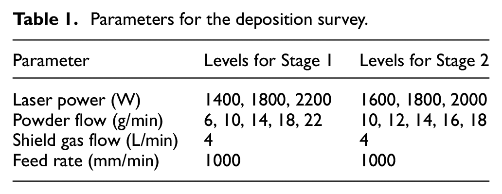
Throughout the assessment of the hybrid manufacturing production of stainless steel 316L components, the DMG Lasertec 65 3D hybrid manufacturing centre was used. This platform allows for the hybrid manufacture of components using a 5-axis mill turning capability. Stainless steel 316L is a common material used in a range of different applications and industries including medical, offshore and automotive. The first step in the manufacturing process is the identification of the best combination of process parameters that produce a good quality build. In order to identify them, a series of single lines were deposited with a range of process parameters. The investigation was done in two stages with the first identifying the rough parameters that are appropriate for deposition and the second stage fine tuning the parameters in the identified range. The main process parameters as well as their levels are presented in Table 1.
Parameters for the deposition survey.
After the single lines have been deposited, the samples were visually inspected and then sectioned, polished and etched to reveal the heat-affected zone (HAZ) and pores and cracks present in the builds. The sectioned areas were examined with a Leica DSM1000 microscope.
Machining trials
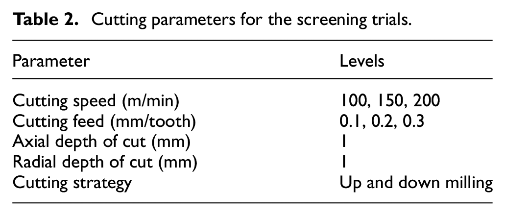
A series of machining trials were performed to quantify the machinability of the deposited material. In order to achieve this, trials were performed on a milling setup on the DMG Lasertec 65 3D. Throughout the trials, a Kistler 9255C dynamometer, with a 1677A5 8-channel charge cable and a 5070 8-channel charge amplifier, was used to measure the cutting forces. The surface roughness after machining was measured with a Mitutoyo Surftest SJ-210 roughness tester. A 20-mm diameter inserted shoulder mill single flute Seco cutting tool was used. For the cutting trials, the failure criterion was VB = 0.25 mm for flank wear. The trials were performed in a dry condition (without coolant) and split into three phases. During the first phase, a series of screening trials were performed on the bulk material using a design of experiments (DoE) approach in order to identify the response of cutting forces and surface quality characteristics when machining the material. These trials were performed for a limited amount of time, and the cutting parameters used are presented in Table 2.
Cutting parameters for the screening trials.
The second phase of the machining trials included a set of life trials on selected cutting parameters in order to identify the machinability of the bulk of the deposited material. The cutting trials were performed using up and down milling. Finally, in the third phase, the machinability of the skin of the material was identified by conducting two life trials for up and down milling, respectively.
Part characterisation
The quality of the components created with the hybrid manufacturing approach was evaluated with a series of testing methods. Deposited geometries were machined using up and down milling strategy using the conditions used for the life trials on the skin of the material. The coupons were sectioned using wire electrical discharge machining (WEDM) and mounted in conductive resin before being polished using standard metallographic techniques. In order to ensure that the deposited material performs as good as an equivalent wrought part, a series of tensile strength tests were performed. The coupons were based on the ASTM E8 coupon.
Results
AM parameter identification
The single tracks created on the hybrid platform were visually inspected in order to identify any macro defects on the build tracks. After that, the coupons were sectioned and prepared for the microscopic assessment. The results of Stage 1 showed that the amount of dilution was a result of a balance between the powder flow rate and the laser power. For very low powder flow rates the dilution was very large (Figure 1(a)), increasing with the increase in laser power, while for very high powder flow rates the dilution was minimal (Figure 1(c)), again increasing with laser power.
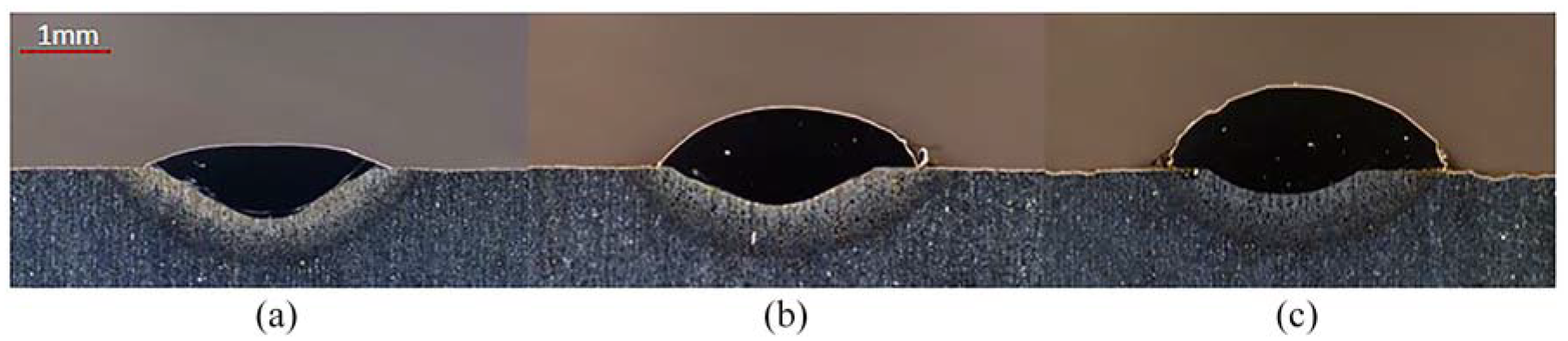
Microscope images of additive single tracks deposited using laser power of 1800 W and powder flow rate of (a) 6 g/min, (b) 14 g/min and (c) 22 g/min.
Comparing Figure 1(a) and (c), it can be seen that the deposited volume was higher with higher powder flow rates, also increasing for laser power. For the highest powder flow rate, the track width did not increase with laser power as seen with lower powder flow rates. This may have shown the maximum bead width possible (~4 mm) using the spot size available on machine. It is also worth noting that there was an inefficient use of powder at high flow rates, with excess un-melted powder surrounding the deposition.
Based on the results of Stage 1, the second stage focused on identifying in greater detail the best parameters for deposition of stainless steel 316L. The parameters surveyed were kept at a tight range, surrounding the region of Stage 1 that showed the best results (Figure 1(b)). Overall, the quality of the deposited beads in the second stage was higher, with much less areas of high dilution and lack of fusion.
When the results from both stages are compiled, it can be seen that the track height linearly increased with powder flow rate (Figure 2(a)) and the HAZ increased with laser power (Figure 2(b)).
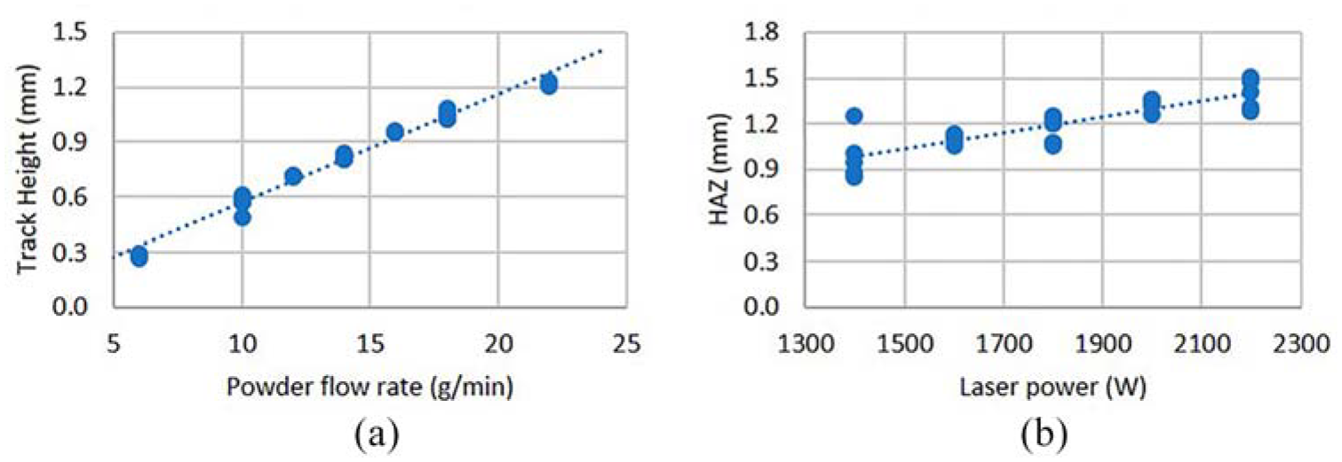
Effect of process parameters on the geometrical characteristics of single tracks: (a) effect of powder flow rate on track height; (b) effect of laser power on heat-affected zone.
Figure 2(b) shows that higher heat input increased the HAZ; however, it has been noted in literature that this heat input and therefore laser power has a large impact on the grain size of the deposited material. 16 This has to be taken into consideration when selecting deposition parameters as grain size has a key effect on the materials mechanical properties. 26
Another key selection criterion is bead shape. Considering that these tracks are to be used to build multi-layer parts, the bead height and width has a large impact on processing times. A bead with larger height and width enables larger step-over and layer height, reducing the number tracks that are required. However, it was seen that when creating larger beads through increased powder flow rates, the powder efficiency decreased. This is an important factor when creating additive parts for industry as low powder efficiencies increase raw material and waste disposal costs.
Fixing the travel speed at 1 m/min reduced the variables impacting the experiments; however, it has been seen by Corbin et al. that like laser power the travel speed has an impact on bead geometry and was the critical influencer of all geometries, greatly affecting bead width and height. 32 By fixing the most influential parameter, this meant that fine tuning the laser power and powder flow rate could be achieved.
Machining trials
For the machining trials, a total of five coupons were built, one large component for the bulk trials and four thin walls for tests on the skin of the part. As mentioned in section ‘Machining trials’, in the first phase, a series of screening trials were performed following an orthogonal DoE design. The DoE design was replicated for up and down milling. The responses measured included the surface roughness on the shoulder created, any evidence of tool wear and the cutting force components in each direction. The results for the screening trials for both up and down milling are presented below. Figure 3 presents the maximum and minimum forces recorded on each of the screening trials in both up and down milling.
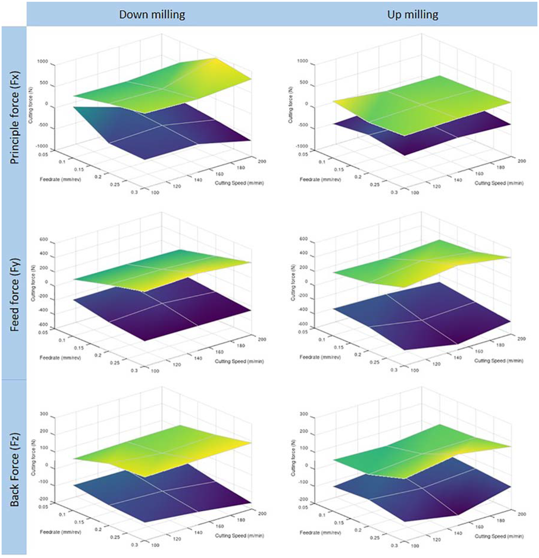
Cutting force results for the screening trials phase.
Comparing the data from up and down milling at the maximum and minimum values, it can be seen that the force in the x-direction (radial depth of cut direction) started and remained much lower for up milling. In general, the cutting forces showed an increase with the increase in cutting parameters, which is a well-established trend. It appears that feed rate had a stronger effect on the change in cutting forces when compared to cutting speed. Focusing on the cutting forces in the y- and z-directions, results were very comparable between up and down milling. With regard to the surface quality, it was observed that up milling provided a much worse surface finish compared to down milling as a lot of material was adhering on the tool and was redeposited on the machined surface, which was not the case in down milling. For the tool life trials, the parameters selected are presented in Table 3. The focal point of the trials was the centre point of the DoE of the screening trials with pairwise comparisons made to investigate the effect of cutting parameters on tool life.
Cutting parameters for the life trials.
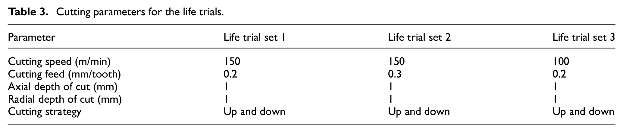
The results for the three sets of life trials are presented in Figure 4. In the life trial set 3, for down milling, the cutting trial was stopped at 82 min due to time constraints with tool wear at 84 μm. For each of the three parameters, the tool life was found to be much longer when using down milling.
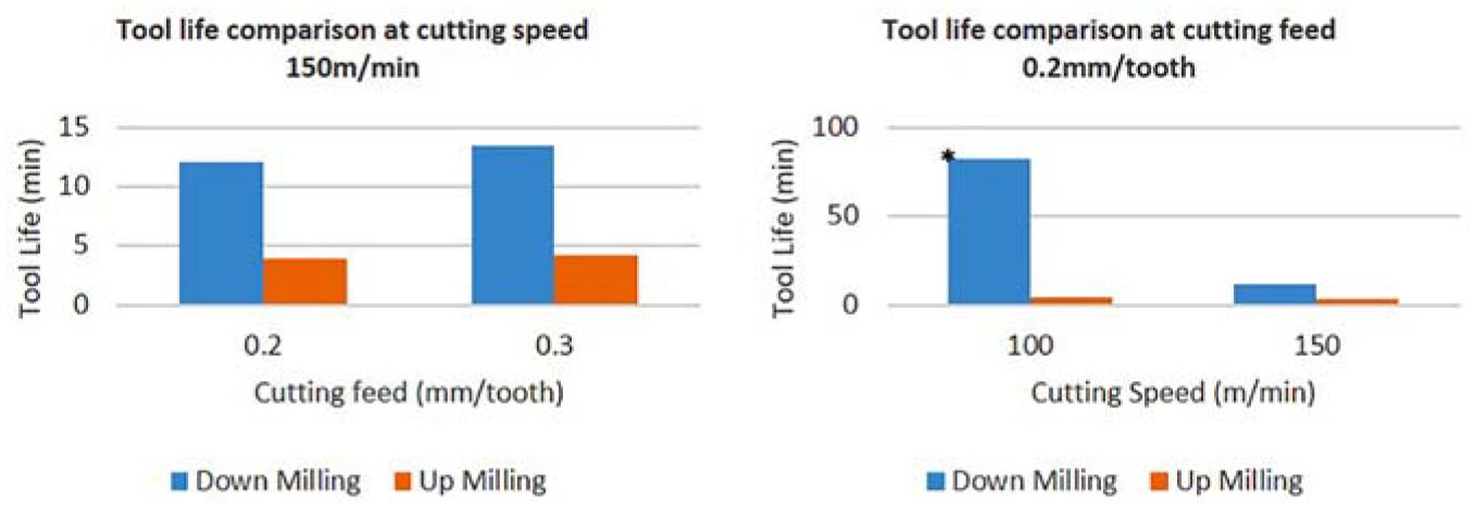
Tool life comparison across different cutting conditions.
In all trials, down milling outperformed up milling, in terms of tool life and surface quality. Up milling is reported to be more stable; however, due to chips adhering to the cutting edge and being redeposited into the cutting zone, the surface finish was much worse than when using down milling at the same parameters.
Figure 5 presents the tool condition for trials carried out when the tool failure criterion was reached. In all cases, shorter tool life was recorded for up milling than down milling and typical wear was seen for each type of milling, with down milling failing due to notching at the workpiece surface and up milling providing wear over a larger area of the tool. Feed rate appeared to have a strong effect on the tool life in down milling; however, this was not the case in up milling. In terms of tool wear mechanisms, in down milling, depth of cut notching was predominantly visible. In up milling, the same mechanism was present but to a greater extent and expanding beyond the depth of cut area which is also supporting the fact that an amount of redeposited material was machined during the cutting operation.
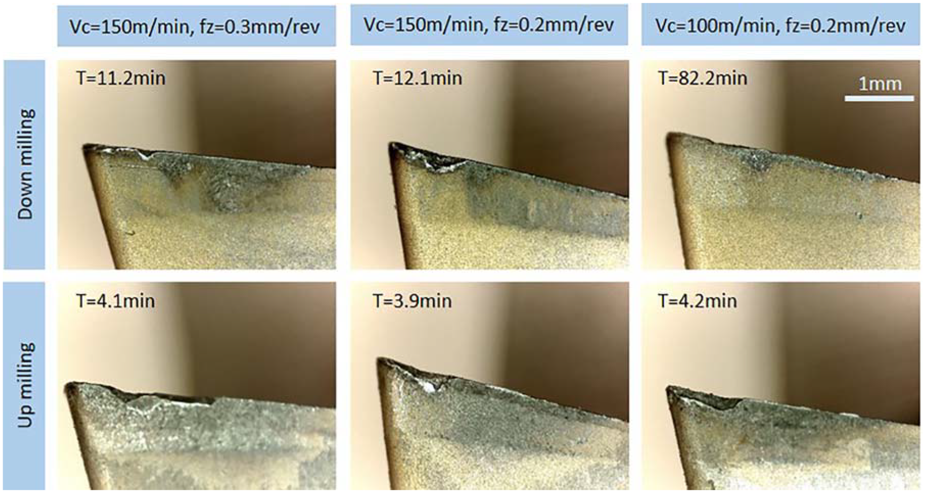
Tool condition at the end of tool life for each cutting condition of the tool life trials.
The outer-surface of AM material often referred to as a skin, cools much quicker than the bulk of the material. This causes differences in microstructure and material properties. For the third stage of the machining trials, a set of tool life trials were carried out on thin wall AM coupons to compare the effect on tool life with that of the bulk AM material. Two life trials were done using the same cutting parameters of 150-m/min surface speed and 0.2-mm/rev feed, comparing up and down milling. Figure 6 presents the results from the life trials on the skin of the coupons, with tool failure being classed as wear exceeding 0.25 mm.
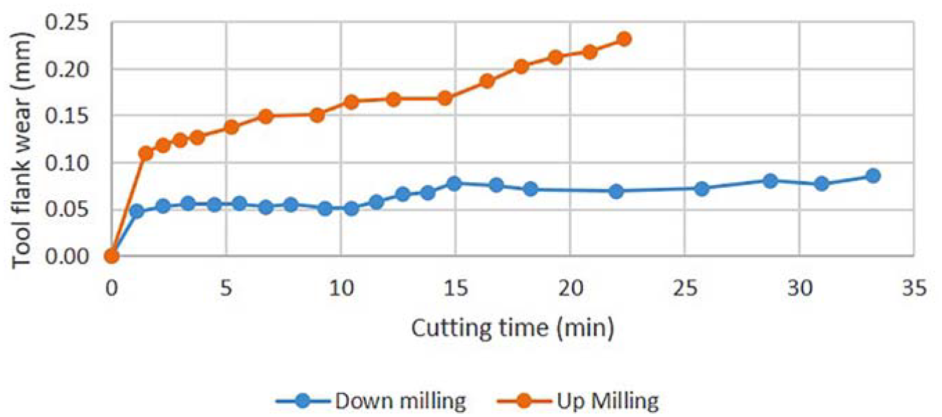
Thin wall up versus down life trial surface speed (Vc) – 150 m/min, feed (Fz) 0.2 mm/rev.
Using up milling, the tool failed after 21 min of cutting; however, for down milling, the tool did not fail after 33 min of cutting, at which all the thin wall material available had been used. The very small levels of wear that had been caused after 33 min of cutting, compared to the same parameters on the bulk material which failed on average after 12 min.
By collating the results in the last two stages of the machining trial, a comparison between the machinability of the skin and the bulk of the additively manufactured material can be realised. Figure 7 shows the difference found in machinability between the bulk and skin AM material, present for both up and down milling, indicating tool life is much higher when milling the skin compared to bulk AM material. In both up and down milling, the tool life observed was longer in the skin of the material compared to the bulk by a minimum factor of 3.
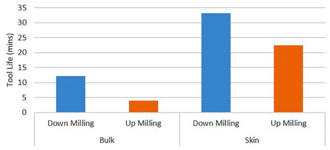
Tool life comparison between skin, bulk, up and down milling.
Figure 8 shows the surface finish of the machined specimens for up and down milling strategies. It can be easily seen that down milling provided a much better surface finish than up milling where adhered chips can be seen.
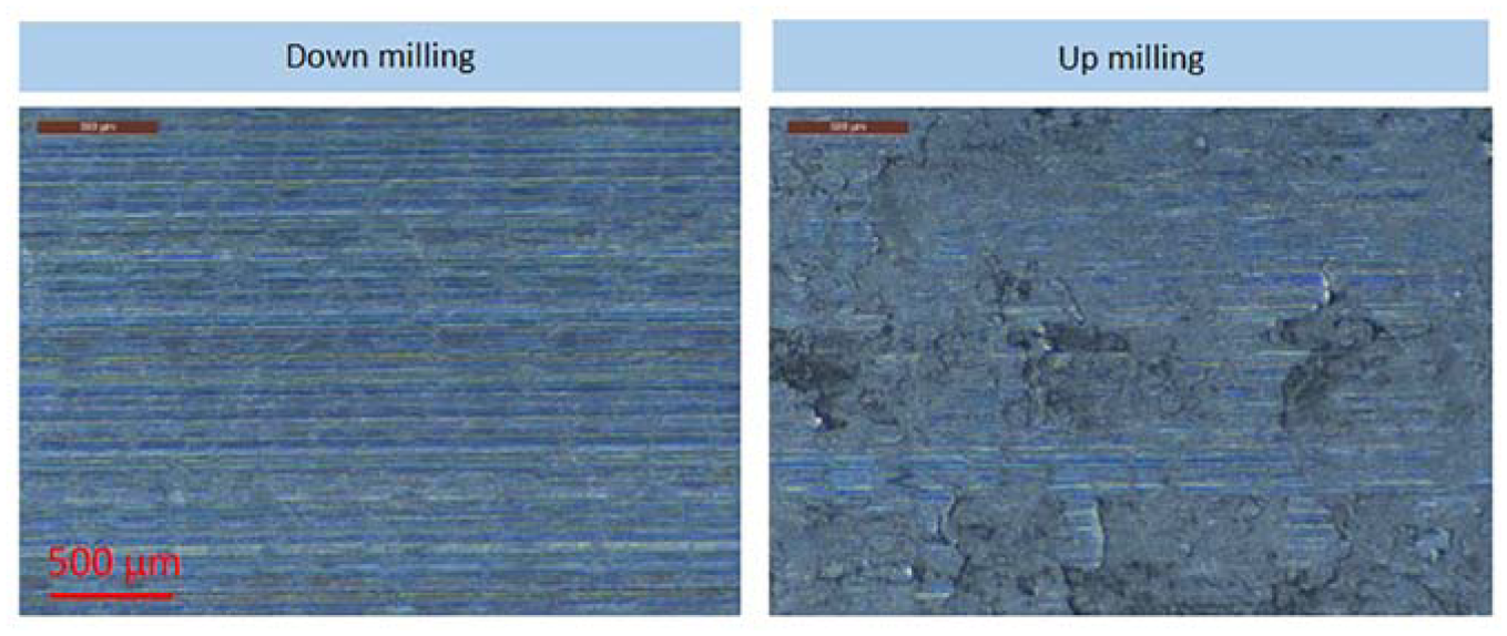
Surface condition comparison between up and down milling trials.
Part characterisation
A series of investigations were performed in additively manufactured coupons in order to evaluate the performance of said components. The characterisation phase of the procedure included tensile tests, computed tomography (CT) and microstructural evaluation of the machined coupons.
Mechanical testing trials
In total, eight samples were deposited for tensile testing. The AM material was removed from the substrate using EDM before it was machined to specification. Figure 9 presents the two orientations as they were deposited as well as a picture of a deposited transverse sample.
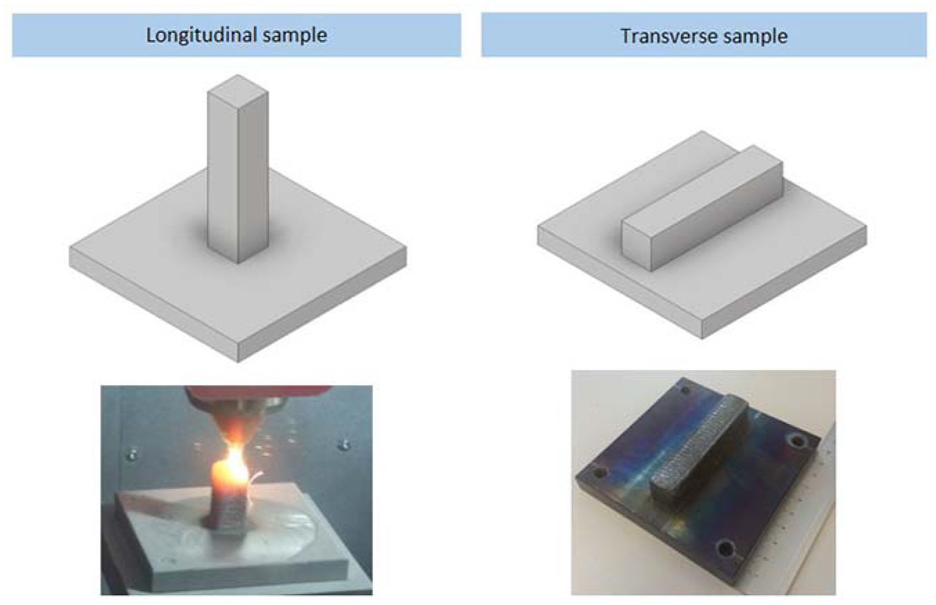
Build orientation of mechanical testing coupons.
Figure 10 presents the results from the tensile tests. It can be seen that the transverse direction compares well to the baseline 316 stainless steel values from a forged part. The lower strength of the longitudinal direction is likely to have been caused by the high temperature sustained during the build, caused as seen in Figure 9.
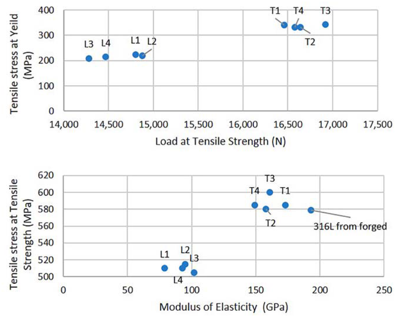
Tensile stress at yield (MPa) versus load at tensile strength (N) and tensile stress at tensile strength (MPa) versus modulus (GPa) with a baseline result for 316 stainless steel. 33
A pattern noticed in the failure of the tensile specimens was that the longitudinal specimens appeared to fail towards the end of the sample, while the failure of the transverse samples was more central to the specimen. This can be attributed to the heat input during the process and its effect on grain size. The transverse samples had the same heat history in the long direction of the tensile sample. However, for the longitudinal samples, the base plate will have acted like a heat sync for the build at the bottom of the part, drawing heat which literature suggests would create a longer grain structure. At the top of the part, more of the heat was retained in the build, possibly resulting in a finer grain structure. A finer grain size would be associated with a harder, more brittle material, affecting the results of the tensile test.
These results give a good window for the possible mechanical properties of an AM 316L part; however, in order to get data that is specific to a certain part or geometry, the thermal history of this part would have to be replicated. The most accurate way to do this is to take samples directly from an AM build of the desired geometry.
CT results
CT scans were performed on four samples in total. The scans were completed using the Nikon Metrology XTH 225/320 LC machine which enables non-destructive inspection of complex internal features, measuring with a high accuracy to a minimum resolution of 3 microns. The samples were scanned in order to access the build quality, looking for internal defects and porosity. Figure 11 shows the scanned images with defects filled with colours referring to the size of the defect as symbolised in the key, where the diameter in mm refers to the defect diameter. Based on the data from the CT scans, the defect volume is measured at 4.93 mm3 compared to the 2938-mm3 total volume of the specimen. In total, the samples showed a porosity of 0.17%.
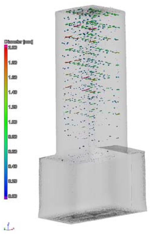
Trimetric view of the CT scanned sample.
Microstructural assessment
A microstructural assessment was performed on machined samples to ascertain the effect of machining on the microstructural condition of the AM coupons. The sections were machined at the centre point conditions (Vc = 150 m/min, Fz = 0.2 mm/rev). The samples were hot mounted in Bakelite, ground and polished using standard techniques. The samples were etched using glyceregia (nitric acid, hydrochloric acid and glycerol). Both samples were examined in a section 90° to the cutting direction. Both examined samples presented plastic deformation in varying degrees. For the sample machined with the up milling strategy the plastic deformation depth observed was 34.5 μm, whereas in the down milling strategy the maximum depth was 18.5 μm. Figure 12 presents the view for both samples. Examination highlighted a heavy deformation area in the near to the surface with a depth of up to 3 μm. As presented in Figure 8, the samples appeared to have wide coverage of adhered material for the samples machined with up milling strategy. Through micrographs, it was specified that for the sample machined with the up milling strategy, the maximum thickness of adhered material was 21.5 μm and covered large areas of the surface. In contrast, the sample machined with the down milling strategy only showed adhered material in small areas with a thickness of up to 4.5 μm.
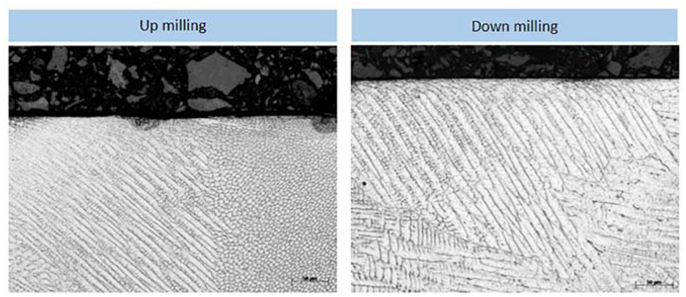
Microstructural assessment of additively manufactured coupons.
Conclusion
In this research, the manufacturing of components through hybrid additive and subtractive machining was investigated. The focus was the investigation of the complete chain between the deposition of the material, using DED method, and the machining and investigation of the final part quality. The first part of the investigation focused on the identification of the best parameters for depositing stainless steel 316L material. The second part of the investigation surrounded the machinability analysis of the deposited material. This included screening trials and tool life trials. The third and final part of the investigation included the characterisation of the mechanical properties of the components manufactured included the orientation of the part with relation to the build direction, the identification of defects in the volume of the material as well as the microstructural evaluation of the machined components.
Observations on the effect of changing parameters showed that the key outputs of build height, dilution and HAZ could be controlled by altering laser power and powder flow rate, while fixing the travel speed and shielding gas flow rate. The track height linearly increased with powder flow rate, with low powder flow rates resulting in high levels of dilution and a larger HAZ, further increasing with laser power. The investigations into the deposition of 316L stainless steel yielded stable and robust parameters, enabling the multi-layer deposition of both block and thin wall structures for machinability trials and material testing.
The machinability trails found that down milling outperformed up milling in terms of tool life and surface finish. Down milling was found to offer 330% longer tool life than up milling in the bulk AM life trials. The surface condition was found to be much poorer when using up milling due to adhered chips, as shown in Figure 7. The most significant result of the machinability study was that the skin layer of the material was found to be more machinable than the bulk of the AM material. This is attributed to the rapid solidification of the material in the periphery of the part that yields different microstructure.
Regarding the component quality, CT scans showed that the parts were not defect free; however, an overall porosity of just 0.17% was found. The tensile tests showed that in the transverse direction the strength was comparable to that of forged stainless steel; however, the heat input caused by the creation of tower like structures showed to reduce the strength noticeably. This was observed in the longitudinal.
Footnotes
Declaration of conflicting interests
The author(s) declared no potential conflicts of interest with respect to the research, authorship, and/or publication of this article.
Funding
The author(s) received no financial support for the research, authorship, and/or publication of this article.