
Abstract
To select the optimum tool material for the cutting of marine high-strength steels using a hole-opening equipment in the marine environment, this article conducted a comparative study on the corrosion property, tribological behavior and cutting performance of cermet, cemented carbide and coated tools. The results reveal that the coated tool materials have good corrosion resistance with coating protection, and poor wear resistance with adhesive and corrosive wear in artificial seawater, and present moderate cutting performance. In addition, the cemented carbide tool materials show poor corrosion resistance and good wear resistance due to the lubrication effect of corrosion products in artificial seawater, but have bad cutting performance with a high flank wear value. Moreover, the cermet tool materials present acceptable corrosion and wear resistance with adhesive and corrosive wear in artificial seawater and have the excellent cutting performance. Taking into account the corrosion resistance, wear resistance and cutting performance of tool materials and regarding cutting performance as an important indicator, the cermet tool materials with superior comprehensive performances are suitable for the cutting of marine high-strength steels in the marine environment.
Introduction
In a maritime emergency response, when a rescue is underway for people who are trapped within an overturned steel ship, it is necessary that a hole be efficiently and safely opened in the hull to allow for an easy access point. 1 Thus, the non-spark explosion-proof and efficient hole-opening technology based on the principle of boring operation was investigated.2,3 However, for the cutting tools used in the marine environment which contains seawater electrolyte solution with about 3.5 wt% NaCl, the cutting condition with seawater corrosion is very different from that in the conventional dry and wet cutting. Meanwhile, a long-life cutting tool without changing is important for a fast rescue. Therefore, for the cutting of marine high-strength steels in the marine environment, it is essential to take not only the cutting performance but also the corrosion property and tribological behavior of tool materials into consideration.
Several scholars have conducted a series of experiments to research the corrosion and tribological behavior of different materials in seawater.4–8 Matei et al. 9 investigated the corrosion resistance of coated tools in artificial seawater and found that TiN and TiAlN coatings can isolate the cemented carbide substrate from marine corrosion. Qiao et al. 10 reported that B4C-based ceramic showed superior corrosion resistance in the marine environment. Qiu et al. 11 demonstrated that (Ti,Ta,Nb,W)(C,N) can greatly enhance the corrosion resistance of cemented carbides. Wan et al. 12 pointed out that the environment had important effects on the erosion–corrosion degradation of Ti(C,N)-based cermets. Shan et al. 13 reported that the corrosion and wear of TiN and TiCN coatings in artificial seawater had a positive synergism. However, few comparative investigations were carried out on the corrosion property and tribological behavior of different tool materials in seawater systematically. In addition, there are few studies on the cutting of marine high-strength steels. Currently, high-strength steels are mainly machined by tools made of cermet, coated cemented carbide, cemented carbide and ceramic materials.14–16 For the cutting of marine high-strength steels using a hole-opening equipment in the marine environment, the tools must have high strength and good impact toughness, therefore the tool materials of cermet, cemented carbide and coated cemented carbide were chosen as the research objects in this work.
To reveal the corrosion property and tribological behavior of different tool materials in seawater, the potentiodynamic polarization and sliding wear experiments were conducted. Meanwhile, the turning experiment of marine steels was carried out to study the cutting performance of tool materials. The research results can provide guidelines of tool material selection for the cutting of marine steels in the marine environment.
Experimental procedures
Tool materials
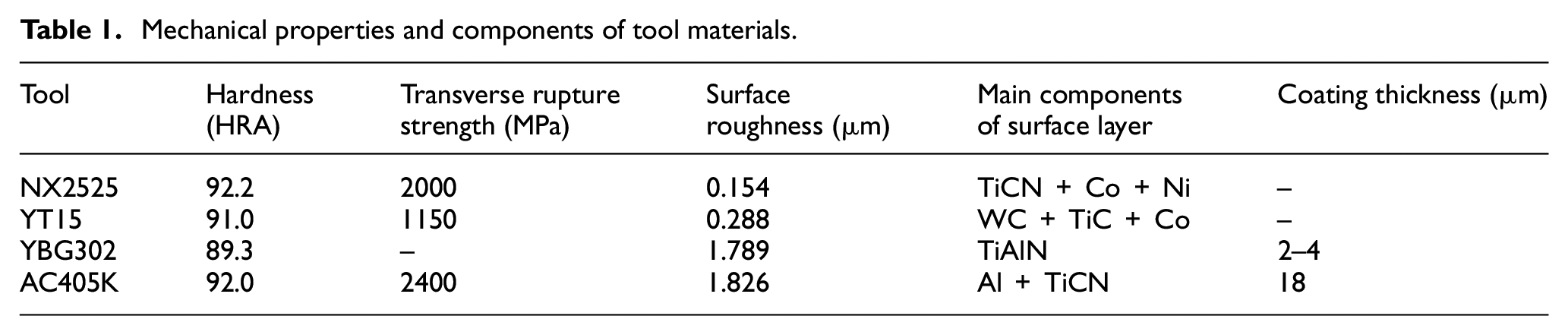
As mentioned above, the tool materials of cermet, cemented carbide and coated cemented carbide were chosen as the research objects in this work. As different experiments required different shapes and sizes of samples, different grades of inserts were used in the following experiments. The commercial tools of NX2525 cermet tool (Mitsubishi Materials Corporation; Japan), YT15 cemented carbide tool (Zhuzhou Cemented Carbide Cutting Tools Co., Ltd; China), YBG302 PVD TiAlN coated cemented carbide tool (Zhuzhou Cemented Carbide Cutting Tools Co., Ltd) and AC405K CVD Al/TiCN coated cemented carbide tool (Sumitomo Electric Industries, Ltd; Japan) were chosen for the potentiodynamic polarization and sliding wear experiments. And before experiments, the NX2525 tool and YT15 tool were polished to eliminate the surface scratches, and then were cleaned with acetone by ultrasonic vibration. To avoid damage of the coating surface, the coated tools were not polished and were only cleaned with acetone by ultrasonic vibration. The mechanical properties and main components of tool materials are shown in Table 1.
Mechanical properties and components of tool materials.
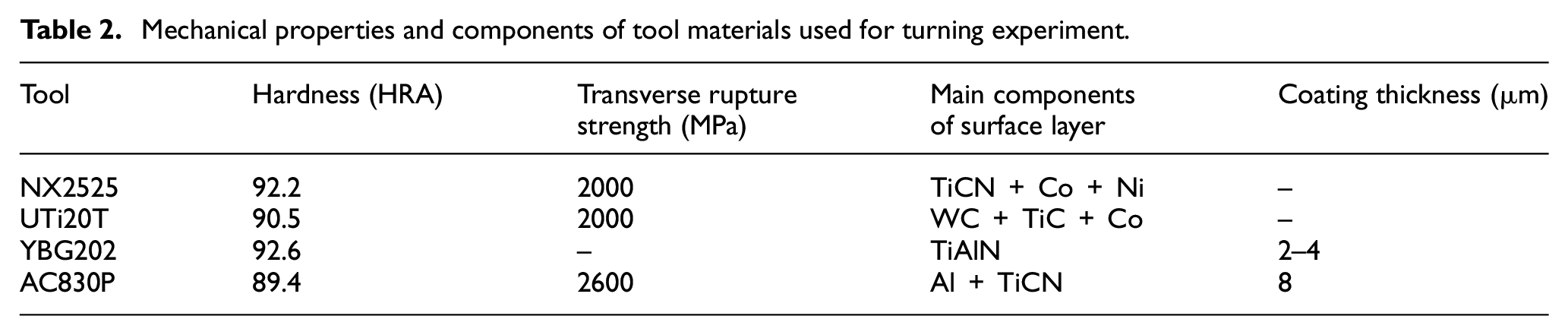
In addition, the commercial tools of NX2525 cermet tool (Mitsubishi Materials Corporation), UTi20T cemented carbide tool (Mitsubishi Materials Corporation), YBG202 PVD TiAlN coated cemented carbide tool (Zhuzhou Cemented Carbide Cutting Tools Co., Ltd) and AC830P CVD Al/TiCN coated cemented carbide tool (Sumitomo Electric Industries, Ltd) were used for the turning experiment of marine steels. The mechanical properties and main components of tool materials are shown in Table 2. Moreover, although the grades of inserts were different, the YT15 and UTi20T tools were made of cemented carbide tool materials, and the YBG302 and YBG202 tools had the same kind of PVD TiAlN coatings. Also, the AC405K and AC830P tools had the same kind of CVD Al/TiCN coatings.
Mechanical properties and components of tool materials used for turning experiment.
Potentiodynamic polarization experiment
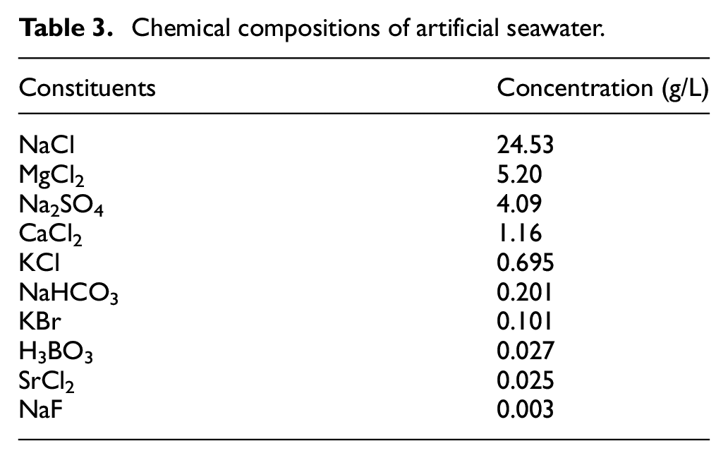
Potentiodynamic polarization test was carried out with the ISO 17474-2012 standard at room temperature (25 °C) in artificial seawater using an electrochemical workstation (Ametek VMP3; USA). The standard three-electrode system with the working electrode (WE) of specimen electrode, counter electrode (CE) of platinum net and reference electrode (RE) of saturated calomel electrode (SCE) was used for the potentiodynamic polarization test. Before the test, the samples were immersed in electrolyte for 30 min. All specimens were polarized from –0.5 to 1.5 V (vs open-circuit potential) with a scan rate of 1 mV/s. The corrosion potential (Ecorr) and current density (Icorr) were analyzed by the installed Tafel-type fit analysis software (Bio-Logic EC-Lab V10.37; France). The corrosion morphologies of tool materials were observed by a scanning electron microscopy (SEM) with an energy-dispersive spectroscopy (EDS; JEOL JSM-7610F; Japan). The compositions of artificial seawater were configured in accordance with the ASTM D 1141-98 standard, as shown in Table 3.
Chemical compositions of artificial seawater.
Sliding wear experiment
Because the hole-opening equipment was investigated based on the principle of boring operation, the linearly reciprocating ball-on-flat tribometer (Lanzhou Zhongke Kaihua Technology Development Co., Ltd CFT-1; China) was used to study the tribological behavior of tool materials at room temperature. Because both marine steel and stainless steel belong to steels, the AISI 304 stainless steel balls with a diameter of 4 mm were used as the counter material, and the tool materials were used as the lower disk samples. The conditions of sliding wear experiment according to the ASTM G133-05 (2016) standard are shown in Table 4. To better reveal the corrosive effect of seawater on tool materials, the comparative sliding wear experiments in air and distilled water were also carried out, respectively. For each sliding wear experiment, five samples were measured under the same conditions, respectively. A confocal laser scanning microscope (Olympus OLS4000; Japan) was used to observe the worn surfaces, and the cross-sectional areas of wear scars were calculated by the installed software. The microstructures and morphologies of worn specimens were analyzed by SEM and EDS (JEOL JSM-7610F; Japan). Based on the wear equation, 17 the wear rate is obtained by the below equation
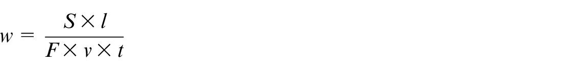
where w is the wear rate (mm3/(N·m)), S is the cross-sectional area of wear scar (mm2), l is the displacement amplitude (mm), F is the applied load (N), v is the sliding speed (m/min) and t is the test time (min).
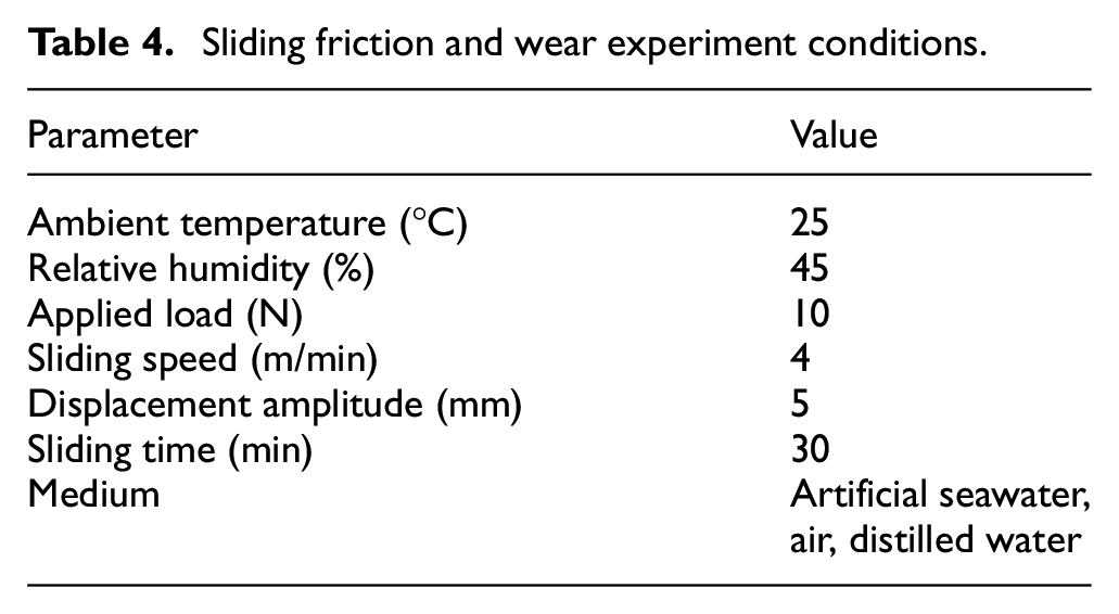
Sliding friction and wear experiment conditions.
Turning experiment
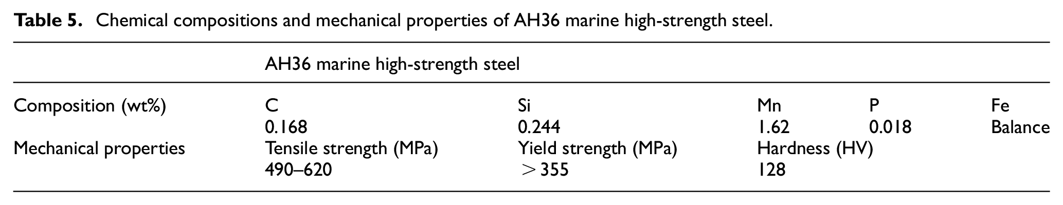
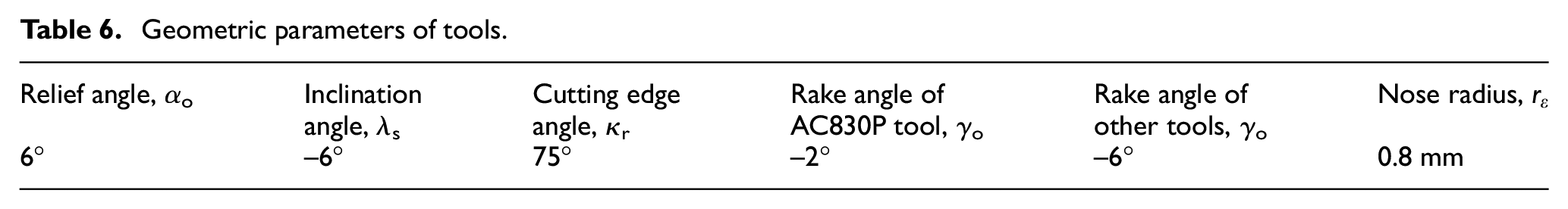
The workpiece material was AH36 marine high-strength steel bar with an 85-mm diameter and a 500-mm length. The chemical compositions and mechanical properties of AH36 steel are listed in Table 5. The turning experiment was conducted on a CA6140A lathe under the cutting speed of 70 m/min, cutting depth of 2 mm and feed rate of 0.15 mm/r in a wet cutting condition for 15 min. The geometric parameters of clamped tools are listed in Table 6. In the initial cutting stage, the cutting force and cutting temperature were obtained by a dynamometer (KIRSTER 9272; Switzerland) and a thermal infrared imager (FLIR A325SC; USA), respectively, and their values were means of five measurements. After the turning, the flank wear value (VB) and worn morphologies of tools were analyzed using a handheld tool microscope (TIME AM413ZT; China).
Chemical compositions and mechanical properties of AH36 marine high-strength steel.
Geometric parameters of tools.
Results and discussion
Corrosion property
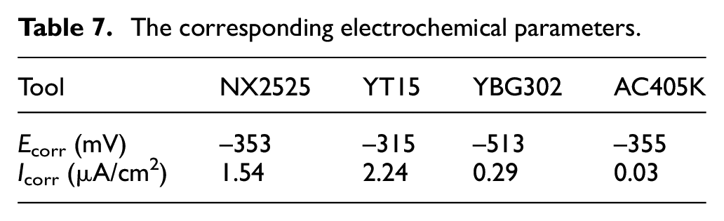
The polarization curves of tool materials are shown in Figure 1, and the corresponding electrochemical parameters are shown in Table 7. It can be seen that the anodic polarization curves of NX2525 and YT15 tools showed an obvious pseudo-passivation behavior as reported in the literature.18,19 Meanwhile, the current density of YBG302 and AC405K coated tools had a small reduction in the active dissolution region. In addition, as shown in Table 7, the Ecorr of YT15 tool was more positive than those of the other tools. And for the YBG302 TiAlN coating, the Ecorr was shifted to a more negative value. Although the Ecorr can represent the thermodynamic stability of tool materials under electrochemical corrosion condition, the Icorr which represents the kinetics of materials’ corrosion can more exactly reflect the corrosion behavior than the Ecorr. 11 From the view of Icorr, the sequence of corrosion resistance of each tool in artificial seawater was AC405K > YBG302 > NX2525 > YT15. The result indicated that the coatings improved the corrosion resistance of cemented carbide substrate materials, and the cemented carbide tool material had the poor corrosion resistance in artificial seawater.
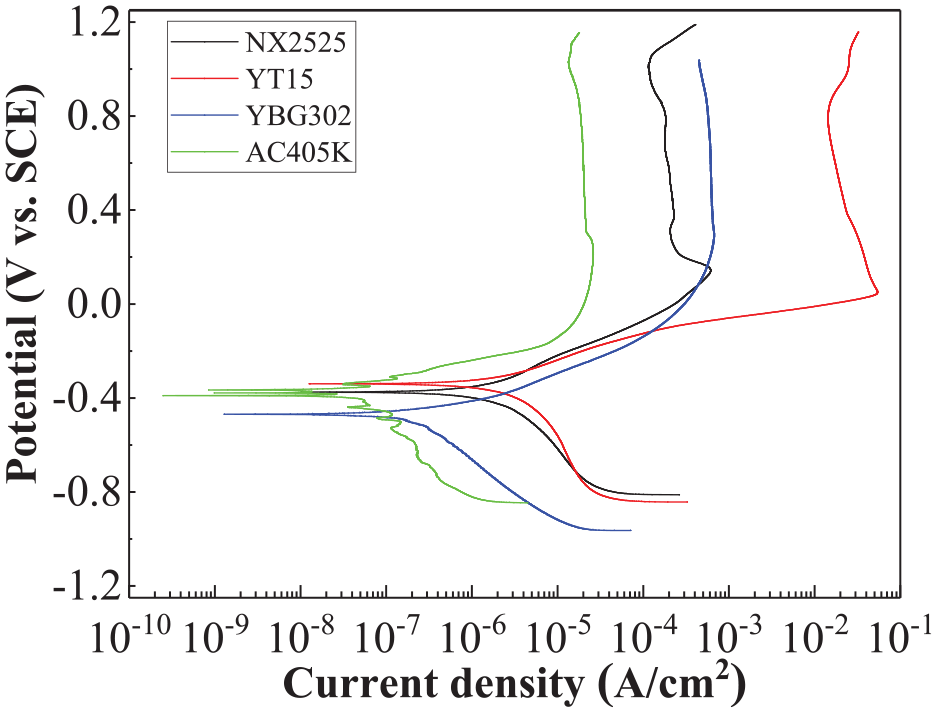
Polarization curves of tool materials in artificial seawater.
The corresponding electrochemical parameters.
To reveal the corrosion resistance of tool materials in artificial seawater, the morphologies of tool materials before and after the potentiodynamic polarization experiment were analyzed, as shown in Figure 2. And the element contents of tool surfaces in the square areas were measured by EDS, as indicated in Table 8.
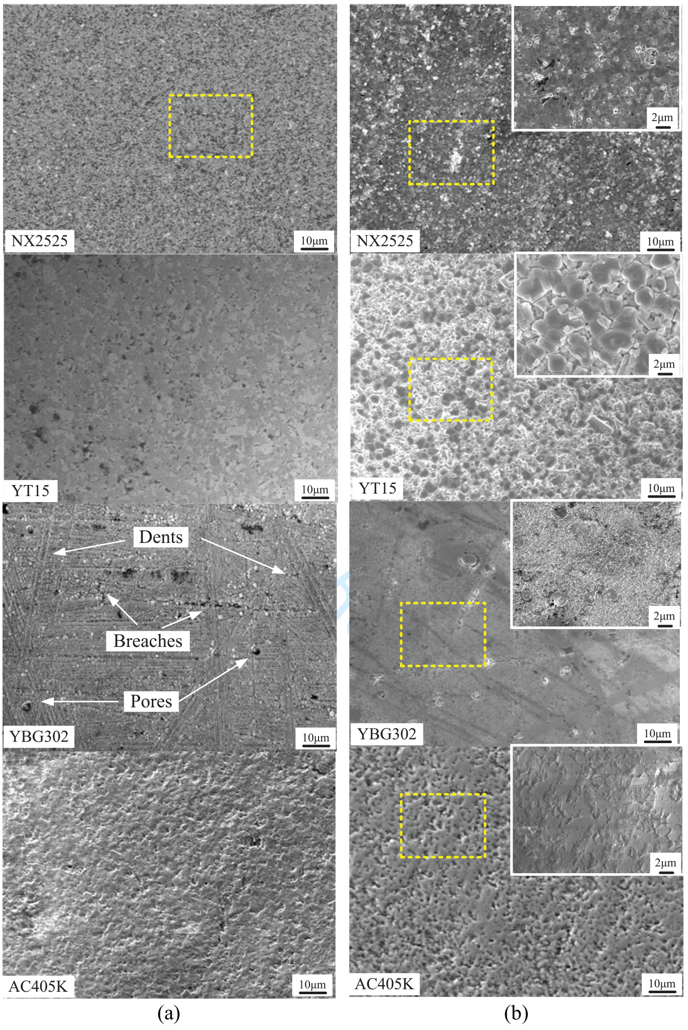
Morphologies of different tools: (a) before and (b) after potentiodynamic polarization experiment.
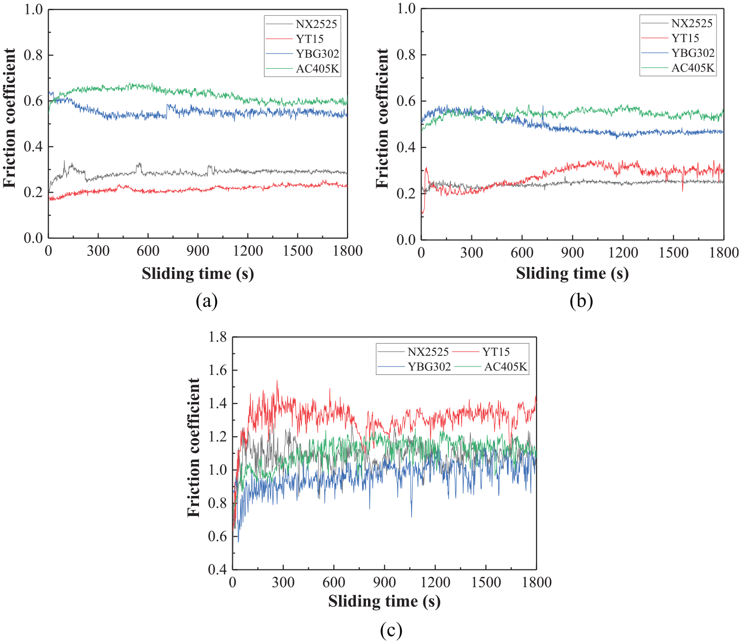
Element contents of tool surfaces analyzed by EDS (corresponding to Figure 2).
As shown in Figure 2(a), there were obvious dents, pores and breaches on the initial surface of YBG302 coated tool. These defects had easy access to the corrosion medium,9,20 therefore the Ecorr of YBG302 coated tool was more negative than those of the other tools. In addition, the polished smooth surfaces of NX2525 and YT15 tools and the compact coating of AC405K tool contributed to their higher Ecorr.
As shown in Table 8 and Figure 2(b), after the potentiodynamic polarization experiment, the contents of metal binders (namely, Co, Ni and Mo) in NX2525 tool decreased, and many small pits appeared on the tool surface. This indicated that the metal binders were much more vulnerable to be corroded with electrode potential increasing, and this resulted in the bigger Icorr. As shown in Figure 2(b), the grain boundaries of YT15 tool were obvious. This indicated that the Co binders in YT15 tool were also corroded seriously, and this caused the Icorr of YT15 tool much bigger than those of the other tools. Moreover, as a result of the formation of passive films, such as Ni(OH)2 and Co(OH)2,21,22 the NX2525 and YT15 tools presented decreased current density in the active dissolution process. In addition, in virtue of the chemical inertness of coating materials, the tool coatings isolated the cemented carbide substrate from the corrosive medium. Therefore, the Icorr of AC405K and YBG302 coated tools was smaller than those of NX2525 and YT15 tools. Meanwhile, the elements of O and Al on the surface of AC405K coated tool indicated that the corrosion products were mainly Al2O3, which improved the corrosion resistance of AC405K coated tool with the smallest Icorr.
Friction coefficient
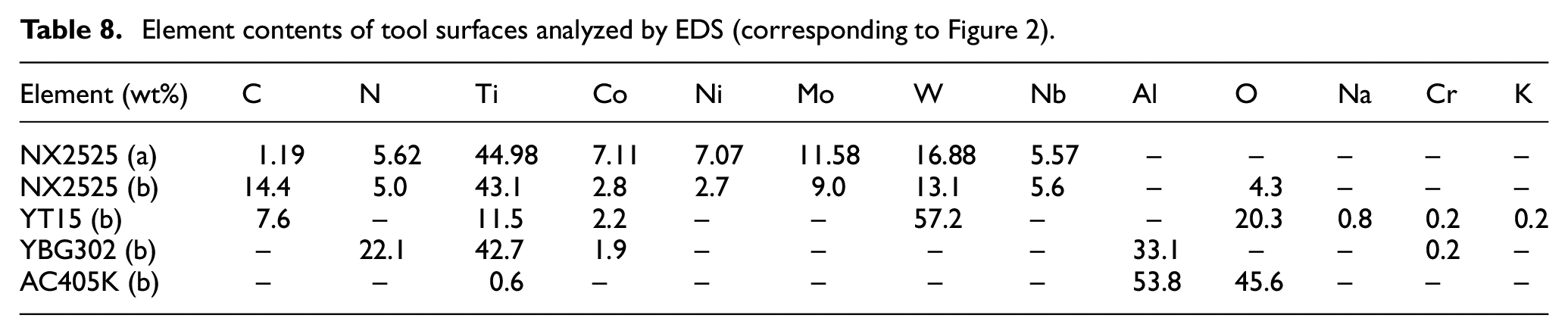
The friction coefficients of tool materials versus sliding time in different mediums are shown in Figure 3. It was obvious that the friction processes of all tool materials in artificial seawater and distilled water were much more stable than those in air. In addition, the friction processes of tool materials in artificial seawater and distilled water also indicated the different influences of both mediums on the friction coefficients.
Friction coefficients of tool materials versus sliding time in various mediums: (a) in artificial seawater, (b) in distilled water and (c) in air at v = 4 m/min and under F = 10 N.
As shown in Figure 3(a) and (b), several big fluctuations of friction coefficient occurred in the friction process of NX2525 tool sliding in artificial seawater, and the trend of friction coefficient of NX2525 tool sliding in distilled water was very stable. While for YT15 tool, the trend of friction coefficient in artificial seawater was much more stable than that in distilled water. The observed phenomenon above for NX2525 and YT15 tools is explained below. Due to the corrosive effect of artificial seawater, the surface of NX2525 tool in artificial seawater was worn unevenly, and this caused the big random fluctuations of friction coefficients in the friction process. Contrarily, when sliding in distilled water, the NX2525 tool presented excellent wear resistance with liquid lubrication. For the YT15 tool, because of the bad corrosion resistance in artificial seawater, it was easy to generate corrosion products of Co(OH)2 on the tool surface, 21 which had lubrication effect during the friction process. 13 Thus, the YT15 tool showed a more stable trend of friction coefficients in artificial seawater than that in distilled water. Besides, as Figure 3(c) illustrates, the friction processes of AC405K and YBG302 tools in air were more stable than those of NX2525 and YT15 tools. This can be attributed to the Al2O3 formed on the coatings, which prevented direct contact of the counter material and mitigated the extent of adhesive wear. 23
The influences of various mediums on the friction coefficients of tool materials are illustrated in Figure 4(a). For the tool material sliding in artificial seawater, the sequence of friction coefficients in general was AC405K > YBG302 > NX2525 > YT15. And the sequence of friction coefficients in distilled water was AC405K > YBG302 > YT15 > NX2525. Meanwhile, the sequence of friction coefficients in air was YT15 > AC405K > NX2525 > YBG302. Moreover, in virtue of the polished smooth initial surface and liquid lubrication, the friction coefficients of NX2525 and YT15 tools were smaller than those of AC405K and YBG302 coated tools both in artificial seawater and distilled water. Besides, the friction coefficient values of tool materials in air were much higher than those in artificial seawater and distilled water, and some values were over 1.0 as shown in Figure 4(a).
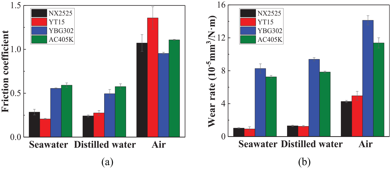
Influences of various mediums on (a) friction coefficients and (b) wear rates of tool materials.
Wear rate
The influences of various mediums on the wear rates of tool materials are illustrated in Figure 4(b). In general, the sequence of wear rates in artificial seawater was YBG302 > AC405K > NX2525 > YT15. And the sequence of wear rates in distilled water was YBG302 > AC405K > NX2525 > YT15. Meanwhile, the sequence of wear rates in air was YBG302 > AC405K > YT15 > NX2525. Moreover, for each tool material, respectively, the sequence of wear rates in different mediums was air > distilled water > artificial seawater. This results of wear rates demonstrated that the cemented carbide tool material had good wear resistance in artificial seawater. The wear mechanisms of each tool material are discussed in the following section to explain the results of wear rates.
Wear mechanism
To explore the wear mechanisms of tool materials in various mediums, the worn morphologies of tool materials and 304 stainless steel balls are illustrated in Figures 5, 7 and 8, respectively, and the corresponding EDS spectrums of points with the weight percentage of each element are presented in Figures 6 and 9, respectively.
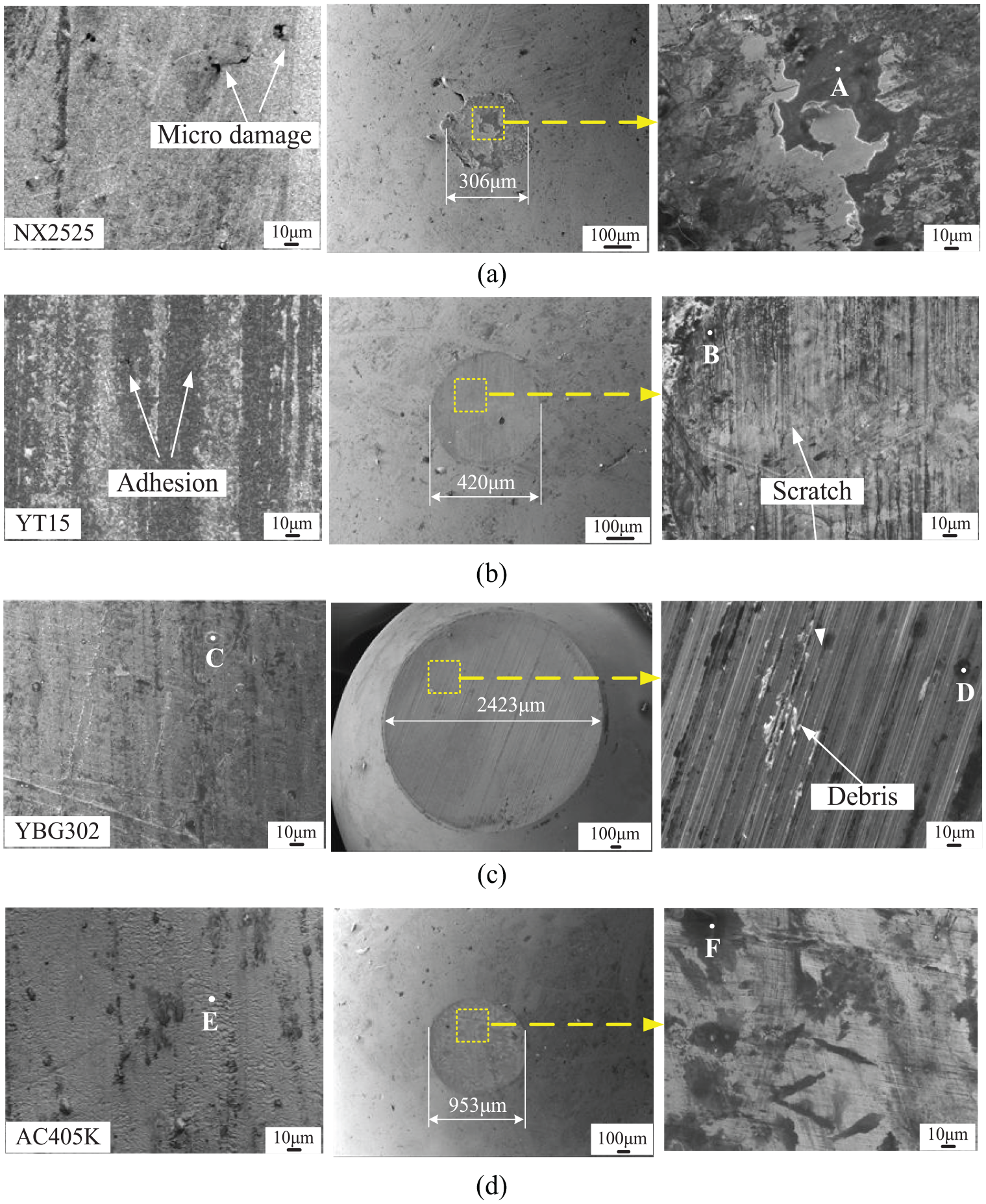
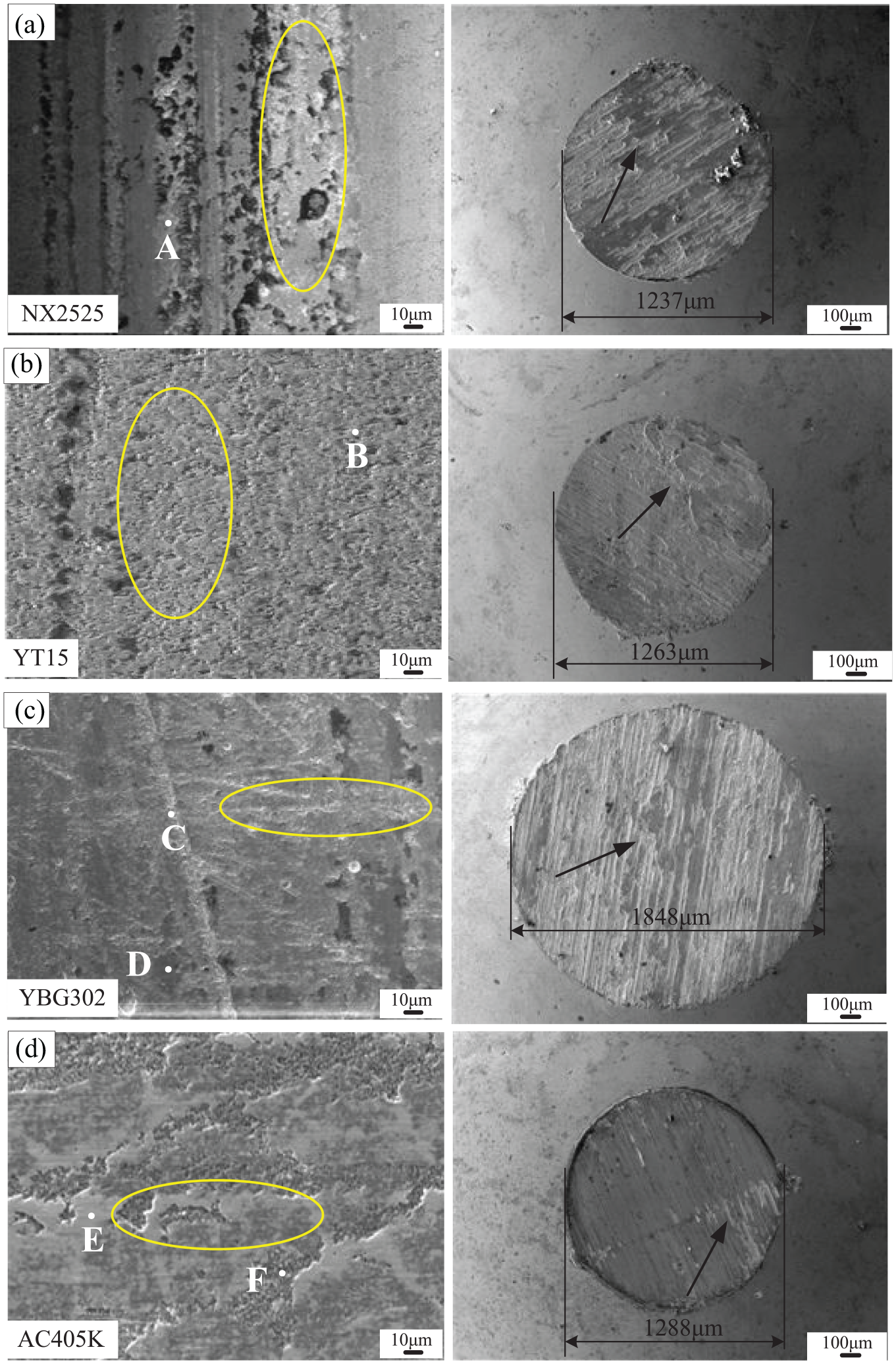
Worn morphologies of tool materials and 304 stainless steel balls in artificial seawater.
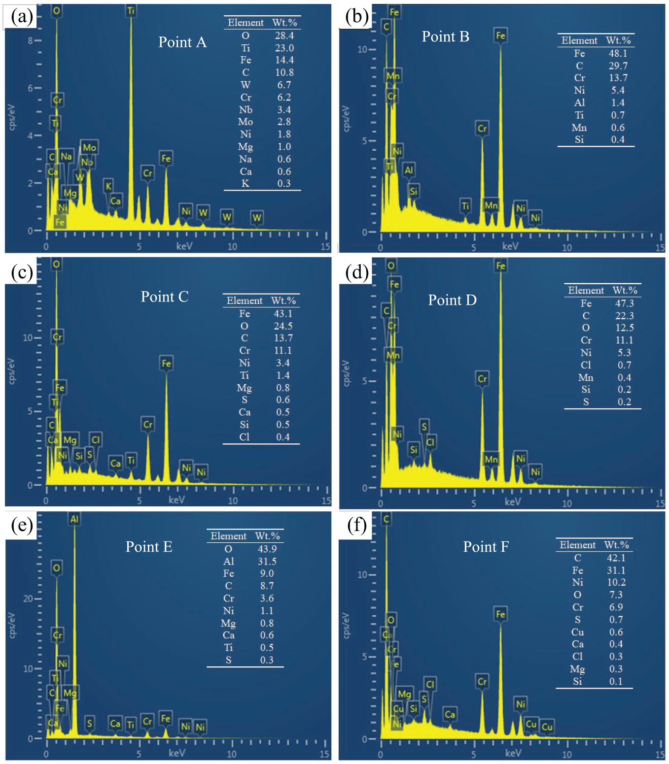
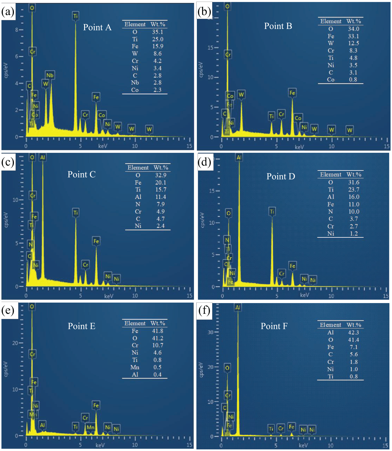
EDS spectrums of point A-F corresponding to Figure 5 with the weight percentage of each element.
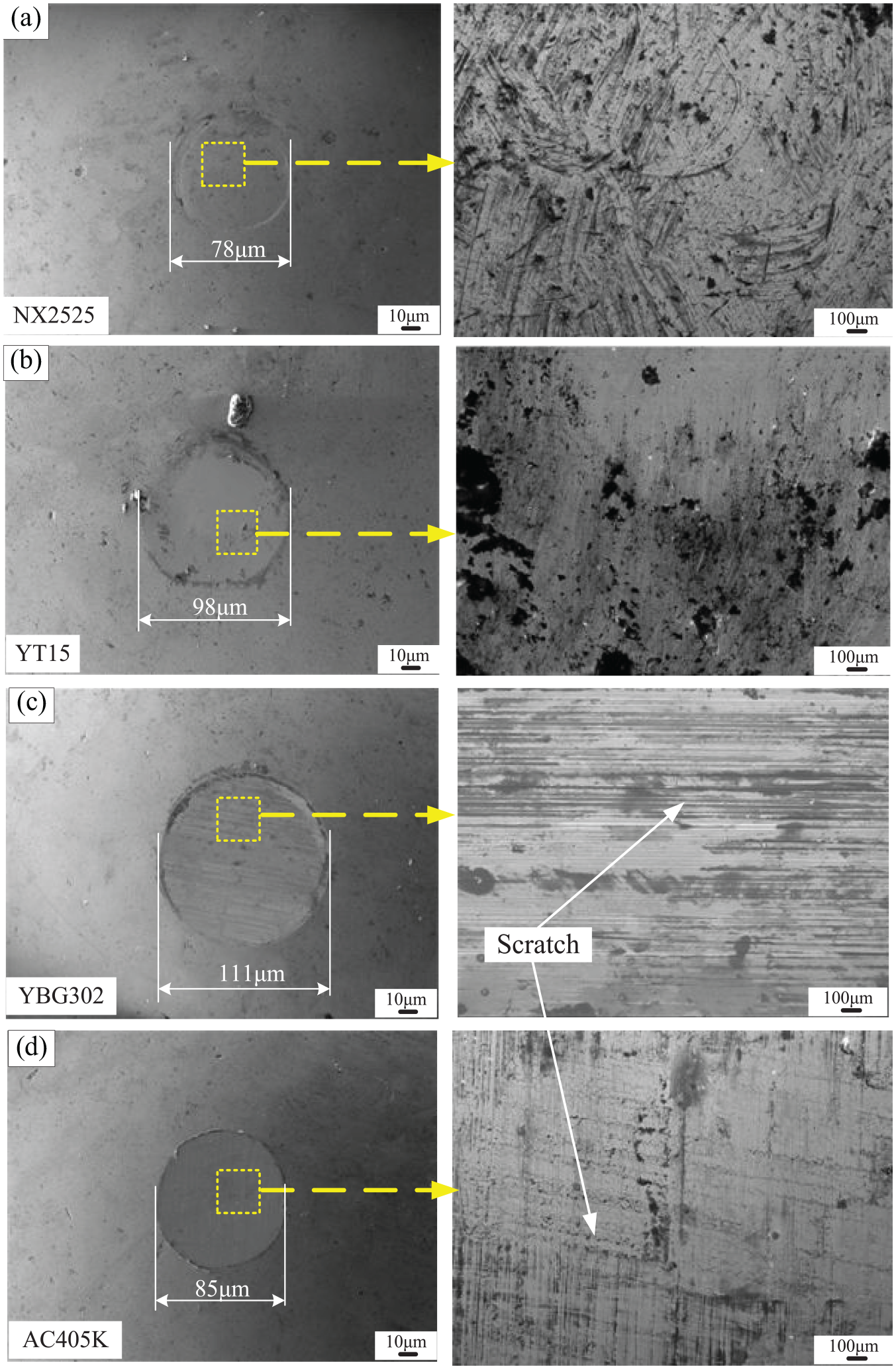
Worn morphologies of 304 stainless steel balls sliding against tool materials: (a) NX2525, (b) YT15, (c) YBG302 and (d) AC405K in distilled water.
Worn morphologies of tool materials and 304 stainless steel balls in air.
EDS spectrums of point A-F corresponding to Figure 8 with the weight percentage of each element.
As shown in Figure 5(a), the micro-damage such as pores and cracks on the surface of NX2525 tool was obvious, and the adhesion of corrosion and wear products containing elements of O, Ti, Fe, Mg and Na (as verified in Figure 6(a)) was found on the surface of steel ball. These were responsible for the random fluctuations of friction coefficient in the friction process. Due to the high hardness of 92.2 HRA, no obvious scratches were found on the surface of NX2525 tool, and this revealed that the wear mechanism of cermet tool material in artificial seawater was adhesive wear and corrosive wear.
As shown in Figures 5(b) and 6(b), there were corrosion products adhered to the surfaces of YT15 tool and steel ball, which can form an easy-shear tribolayer 24 between the tool and the ball in the friction process. Meanwhile, obvious wear scars were also found on the surface of YT15 tool, as a result of the easy pulling out of small grains with binder denudation. 25 This indicated that the main wear mechanism of cemented carbide tool material in artificial seawater was abrasive wear and corrosive wear with adhesive wear. In addition, in virtue of the antifriction effects of easy-shear tribolayer and pulled-out grains, the YT15 tool presented the smallest friction coefficient and wear rate in artificial seawater.
As illustrated in Figure 5(c) and (d), the adhesion of corrosion products (as verified in Figure 6(c)–(f)) was found on the surfaces of YBG302 and AC405K tools and steel balls, respectively. This indicated that adhesive wear and corrosive wear occurred when the coated tool materials slide against steel balls in artificial seawater. In addition, as shown in Figure 5(c), the steel ball was worn badly and presented abrasive wear features with deep scratches and obvious debris on the surface. This illustrated that the friction process between the YBG302 tool and steel ball was serious, as a result of which the YBG302 tool exhibited the highest wear rate (as shown in Figure 4(b)).
Figure 7 indicates the worn morphologies of 304 stainless steel balls sliding against tool materials in distilled water. It can be seen that the worn morphologies of steel balls with abrasive wear features were smoother than those in Figure 5. Meanwhile, as shown in Figure 4(a), the friction coefficients of tool materials except YT15 tool in artificial seawater were bigger than those in distilled water. This illustrated that artificial seawater aggravated the friction process between tool materials and steel balls. Furthermore, compared with Figure 7, the wear scar diameters of steel balls in artificial seawater (as shown in Figure 5) were bigger than those in distilled water, while the wear rates of tool materials in artificial seawater were smaller than those in distilled water (as shown in Figure 4(b)). It can be concluded that the steel materials became much easier to be worn than tool materials under the corrosive effect of artificial seawater. Accordingly, the final wear resistance of tool materials when sliding against steel materials was not subjected to the adverse effect of corrosive wear.
Figure 8 shows the worn morphologies of tool materials and 304 stainless steel balls in air. All the steel balls with severe tearing (as marked by arrows) presented much worse worn morphologies than those in the other mediums. Combining with the EDS spectrums in Figure 9, it can be concluded that severe adhesive wear (as marked by ellipses in Figure 8) and oxidative wear occurred when tool materials slide against steel balls in air. Thus, the friction coefficients and wear rates of tool materials in air were much bigger than those in artificial seawater and distilled water. And the phenomenon of cold welding was responsible for the high values of friction coefficients over 1.0 as shown in Figure 4(a). Besides, as shown in Figure 9(d) and (f), the elements of O and Al on the surfaces of coated tools confirmed the formation of Al2O3, which was beneficial for the stable friction processes (as verified in Figure 3(c)) and the small friction coefficients (as verified in Figure 4(a)) by mitigating the extent of adhesive wear (as verified in Figure 8(c) and (d)).
Cutting performance
Figure 10 illustrates the cutting force and cutting temperature for each tool, and Figure 11 shows the tool wear morphologies, respectively. In addition, the tool flank wear values are listed in Table 9. It can be seen that for each tool, the sequence of cutting force was YBG202 > UTi20T > AC830P > NX2525, and the sequence of cutting temperature was UTi20T > AC830P > YBG202 > NX2525. For the YBG202 tool, the highest cutting force can be attributed to the poor friction coefficient and wear resistance of PVD TiAlN coating (as shown in Figure 4), and this caused coating damaged and matrix exposed (as shown in Figure 11(c)). Due to the severe adhesive wear (as shown in Figure 11(b)), the UTi20T tool presented the highest cutting temperature and caused the corresponding built-up edge. Meanwhile, due to the low thermal conductivity of coatings,26,27 the YBG202 and AC830P coated tools caused higher cutting temperature in the cutting zone. In virtue of the low friction coefficient and good wear resistance (as shown in Figure 4), the NX2525 tool presented the smallest cutting force and cutting temperature.
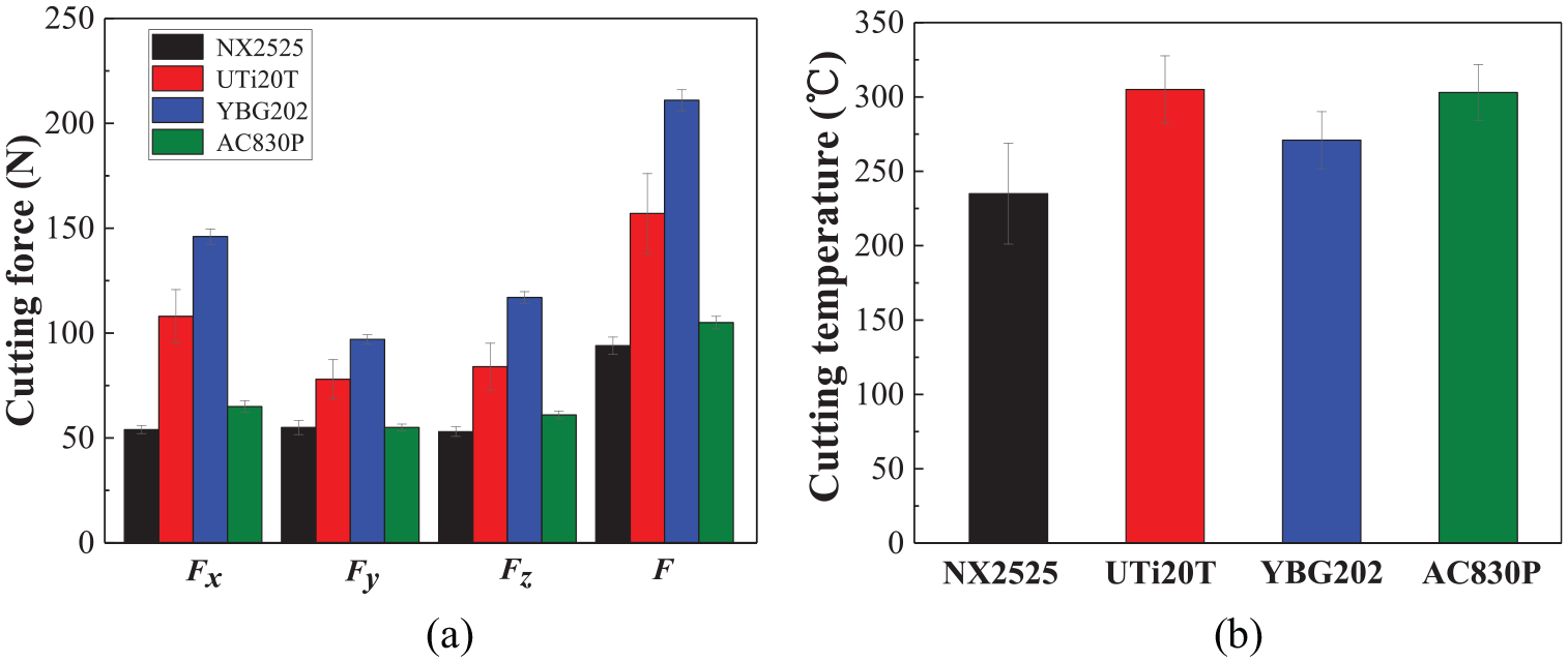
(a) Cutting force and (b) cutting temperature for each tool.
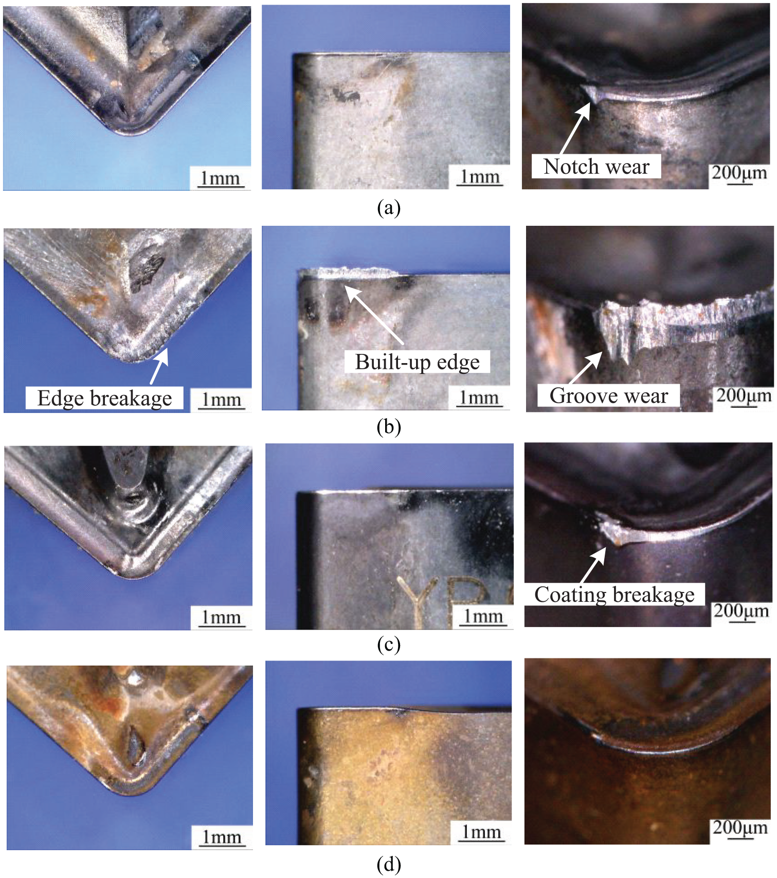
Wear morphologies of different tools: (a) NX2525, (b) UTi20T, (c) YBG202 and (d) AC830P.
Tool flank wear values.
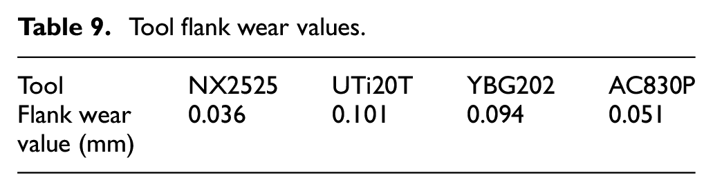
As shown in Figure 11, all the tools showed slight crater wear on the rake face while presented different flank wear and corner wear. The NX2525 tool had flank notch wear with smaller corner wear. In virtue of the smallest cutting force and cutting temperature, the cutting process of NX2525 tool was stable, thus the corner wear was even with a smallest flank wear value (as shown in Table 9). For the UTi20T tool, it showed obvious adhesive wear characteristics with built-up edge, severe groove wear and edge breakage. This indicated that the cutting process was fluctuated, accompanied by the high cutting force and cutting temperature (as shown in Figure 10). Therefore, the UTi20T tool had the largest flank wear value. From Figure 11(c), it can be seen that the flank face and corner of YBG202 tool were worn obviously, due to the coating breakage. And the flank wear value of YBG202 tool was bigger. For the AC830P tool, benefited from the coating protection, the tool corner had slight wear under the smaller cutting force, and the flank wear value was also smaller. Based on the analyses of tool wear morphologies, it can be concluded that the adhesive wear with abrasive wear was the main wear mechanism of UTi20T tool. Meanwhile, the main wear mechanisms of the other tools were abrasive wear.
For the cutting process of opening a hole in hull in a maritime emergency rescue, a small cutting force can make it stable, a low cutting temperature can make it safe from explosion, and a small tool flank wear value can make it efficient. Therefore, for the tools used in the cutting of marine high-strength steels, the sequence of cutting performance was NX2525 > AC830P > YBG202 > UTi20T. The result of cutting experiment demonstrated that the cermet tool materials had the best cutting performance with the smallest cutting force, cutting temperature and flank wear value.
Conclusion
This work conducted a comparative study on the corrosion property, tribological behavior and cutting performance of tool materials for the cutting of marine high-strength steels in the marine environment. The following conclusions can be drawn from this study:
In artificial seawater, for different tool materials, the sequence of corrosion resistance is Al/TiCN coating > TiAlN coating > cermet > cemented carbide. And the sequence of wear resistance is cemented carbide > cermet > Al/TiCN coating > TiAlN coating.
For the tool materials used in the cutting of marine high-strength steels, the sequence of cutting performance is cermet > Al/TiCN coating > TiAlN coating > cemented carbide.
Steel materials become much easier to be worn than tool materials under the corrosive effect of artificial seawater. And the final wear resistance of tool materials when sliding against steel materials is not subjected to the adverse effect of corrosive wear. Thus, for the tool materials used in the marine environment, the cutting performance should be regarded as a more important indicator than their corrosion resistance and wear resistance.
Taking the corrosion resistance, wear resistance and cutting performance of tool materials in consideration, the cermet tool materials, which present superior comprehensive performances with the moderate corrosion resistance, the better wear resistance and the best cutting performance, are suitable for the cutting of marine high-strength steels in the marine environment.
The conclusions above can be used as guidelines for the selection and development of cermet tools, which are custom-made for the cutting of marine high-strength steels using a hole-opening equipment in the marine environment.
Footnotes
Declaration of conflicting interests
The author(s) declared no potential conflicts of interest with respect to the research, authorship, and/or publication of this article.
Funding
The author(s) disclosed receipt of the following financial support for the research, authorship, and/or publication of this article: The research was sponsored by the China Postdoctoral Science Foundation (Grant No. 2017M621121), The Key Laboratory of High-Efficiency and Clean Mechanical Manufacture at Shandong University, Ministry of Education and the Fundamental Research Funds for the Central Universities of China (Grants Nos 3132019352 and 3132019308).