
Abstract
This article purposes on developing and on re-interpreting the numerical results of a topology optimization for a structural component built via additive manufacturing. A critical appraisal of the optimization results is presented by modeling the feasible component with a holistic approach that merges structural and manufacturing requirements. The procedure is expected to provide a design guideline for similar applications of practical relevance, toward an increase of the right-first-time parts that is required to bring additive manufacturing to its full competitiveness. Topology optimization of a steering upright for a Formula SAE racing car was performed by targeting weight minimization while complying with severe structural constraints, like global and local stiffness performance. Cornering, bumping and braking vehicle conditions were considered. The optimization constraints were evaluated via finite element analysis on a reference component, where the loading conditions were retrieved from telemetry data. The reference part was manufactured by computer numerical control machining from a solid aluminum block. Spurred by the interpretation of the topology optimization predictions, a new upright geometry was designed and validated by calculating its stress field and the possible occurrence of Euler buckling. The new upright was 9% lighter than the reference component. The new geometry was analyzed according to Design for Additive Manufacturing principles to choose the orientation on the build platform and the supports’ location and geometry. The part was successfully manufactured and proved consistent with the application.
Keywords
Introduction
Optimization analyses are effective instruments for systematic design in mechanics. In recent years, these techniques are adopted during the design phase of a component. The commonest algorithms, applied to define the optimal solution, include evolutionary structural optimization,1,2 genetic algorithms, 3 solid isotropic material with penalization4,5 and finally, homogenization techniques.6,7 The algorithms, the sensitivity filters, and the manufacturing constraints driving the optimization analysis are widely described. However, the interpretation of the optimization results is scattered throughout various papers and not yet systematized in the literature.8–10 In this article, a critical appraisal of the results obtained by topology optimization (TO) is presented by modeling a feasible component, such as a front steering upright, by beam, plate, and solid structures. A detailed discussion of the design choices is presented in synergy with the additive manufacturing (AM) process opportunities. The front steering upright has been chosen for its complex shape and for its severe operating loading conditions. This component links the upper and lower control arms of a car suspension system to the wheel hub. The upright transfers the forces and the moments from the wheel to the suspension arms. Since the upright represents a significant unsprung mass, reducing its weight could noticeably improve the vehicle stability and handling.11,12
Due to the geometric complexity and the high number of load cases involved, an analytical optimization approach is usually unfeasible, and therefore, optimized designs of the upright have been achieved so far by employing numerical optimization techniques.13–17
Davies and Clarke 13 adopted the TO results to develop the new concept of the uprights of an electric Formula SAE car manufactured via rapid casting technology. The optimized components were found to be structurally efficient, with a decrease in the overall weight of about 14%.
Dumbre et al. 14 applied TO to improve a steel upright. A mass reduction of 11% was achieved despite the very limited design space. Aune 15 introduced a lattice structure with hexahedral cells to interpret the TO results around the wheel hub, to overcome a physically unfeasible intermediate density distribution.
Some contributions16–18 have been dedicated to the material selection for an upright similar to the one addressed in this research. Mesicek et al. 17 discussed the workability and technological manufacturing features of some metal alloys and composites. Kashyzadeh et al. 18 investigated the optimal material distribution for a front upright to achieve demanding vibration and durability targets. Vijayarangan et al. 19 considered a metal matrix composite to substitute spheroidal graphite iron for the steering knuckle. Several contributions20–23 investigated the fatigue behavior of steel and aluminum steering knuckles through a systematic comparison between experimental tests and numerical models and applied various analytical multi-axial fatigue criteria. Mutha et al. 24 considered a steering upright to be manufactured by computer numerical control (CNC) by adopting an iterative process based on linear finite element (FE) analyses.
The design of a vehicle upright manufactured via metal AM through TO is presented by Walton and Moztarzadeh 25 and Reddy et al. 26 and is critically summarized in Plocher and Panesar. 8 In Reddy et al., 26 the minimization of the supporting structures was pursued together with the minimization of the component weight. The pertinent literature offers therefore a wide scenario of geometries for a steering upright, with varying material, manufacturing process, and suspension layout.
In this contribution, a methodology similar to the one presented by Barbieri et al.27,28 and Mantovani et al. 29 was applied to determine the optimal material distribution for an upright to be produced in aluminum alloy by laser-powder bed fusion (L-PBF). 30 L-PBF discloses extreme freedom in geometry, which also enables the production of the complicated shapes resulting from TO.31,32 For automotive applications, L-PBF parts generally require finishing operations to achieve the required surface roughness and dimensional/geometrical tolerances.33,34 However, since the combined exploitation of TO and L-PBF commonly leads to complex freeform shapes, the development of the machining cycle and of the required fixtures can be critical. 35 Often, while developing the final design, extra clamp-points have to be added to the model to ensure a firm fixture according to a Design for Finishing (DfF) strategy.36,37
Design for Additive Manufacturing (DfAM) implies the synergistic optimization of a product together with its AM process to reduce the development time and cost, while increasing performance, quality, and profitability.38,39 DfAM includes the mutual optimization of the part geometry and of its orientation within the machine build volume, to minimize the need of supports and stress-induced deformations.40–42
This article starts from the definition of the load cases by telemetry data, proceeds to FE analysis of the reference steering knuckle, based on the evaluation of local stiffnesses, applies the recorded displacements as design constraints in the TO analyses for the new upright made by AM (as in Zuo et al. 43 and Mantovani et al. 44 ), and uses experimental testing for the definition of the AM material card. The TO model setup and the optimization results are presented and reinterpreted to achieve a preliminary design of the steering upright. The interpretation of TO results is widely discussed; in fact, the above design considerations are applicable to any further mechanical components. In addition, iterative FE validations are presented to reach the optimized upright, which is then analyzed by DfAM and DfF approaches and manufactured.
Analysis of the reference steering upright
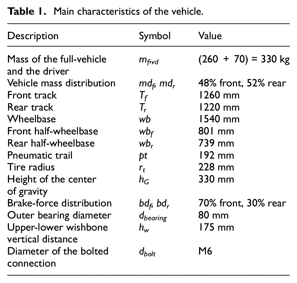
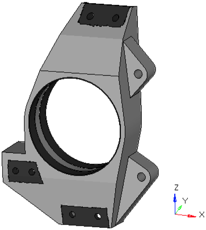
Figure 1(a) and (b) shows the suspension system assembly and the reference upright. Its sizes are summarized in Table 1. The reference upright geometry was defined through a previous TO design addressed to aluminum structures manufactured by CNC. In fact, thin ribs and notches link the double-wishbone attachment to the hub wheel housing. The component thickness along the y-direction ranges from 10 to 45 mm, and its graded profile is shown in Figure 1(b). The average thickness of the inner ribs is 3 mm. The MSC Marc 2013.1 was employed for FE analyses, where the suspension system and the upright assembly were streamlined. Only the upright, the brake caliper, and the bolted connections were modeled. The mean dimension of the elements was as small as 1 mm. The mesh consisted of 243,000 elements: 66,000 pentahedral (isoparametric, six nodes, using six-point Gaussian integration) and 177,000 tetrahedral elements (isoparametric, four nodes, using one-point Gaussian integration). The material of the upright and of the brake caliper was aluminum, while the bolt connections were in steel. Young’s moduli were set to 70,000 and to 210,000 MPa for aluminum and steel, respectively. Poisson’s ratio was assumed to be 0.3.
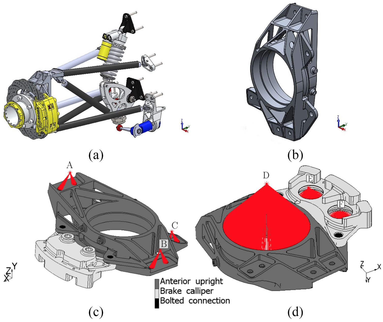
Suspension assembly (a), reference upright (b), and definition of the multipoint constraints RBE2 (c) and of the constraints RBE3 used for the bearing and for the calipers’ piston (d).
Main characteristics of the vehicle.
Some simplifications commonly accepted in the mechanical analysis 11 were introduced in the linear FE model. The tire was assumed to be rigid, where the tire-road contact force was applied to the center of its footprint and this contact point coincided with the projection of the wheel center on the ground. The vehicle was assumed to be in stationary condition and therefore the aerodynamic loads were omitted.
Multi-point constraints (RBE2) were adopted to impose rigid kinematic links between the steering upright and both the double-wishbone brackets (nodes A and B) and the upright and steering tie-rod (node C) (see Figure 1(c) and (d)). The loads were distributed and linking elements (RBE3) were applied to simulate the load transfer between the wheel center and the bearing seats, as well as the loads acting between the piston seats and the caliper (Figure 1(d)).
The upright was constrained by means of statically determinate boundary conditions at the RBE2 reference nodes A, B, and C. These conditions are equivalent to the assumption that the damper-spring system is rigid, and the steering wheel is considered at the stationary status. In fact, a spherical joint was modeled at the node A, a hinge boundary condition lying parallel to the ground (XY-plane) was assumed to be at the node B and, at the connection between the upright and the steering tie-rod, the node C was constrained by a rocker bilateral condition acting along the Y-direction.
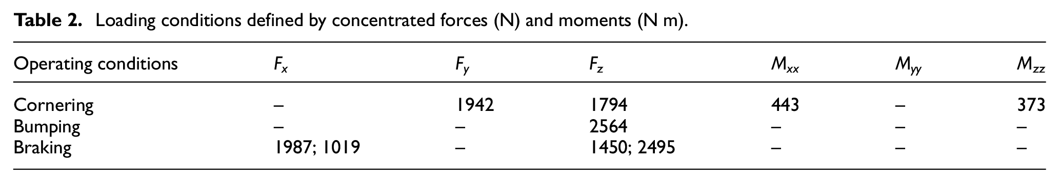
Three load cases were derived from vehicle data telemetry by considering the maximum values of the lateral and longitudinal accelerations and the vehicle main characteristics (Table 1). The loading conditions (Table 2) were applied to the wheel center location, that is, to node D of the RBE3 (see also Figure 2). At this node, the elastic global response of the upright was collected in terms of displacements and rotations. A sensitivity analysis of mesh size on these displacements and rotations has been performed. Table 3 shows the results for models with an average element size of 0.5 and 1.0 mm. The error is evaluated with respect to the model with 1.0 mm element size, and it is lower than 3%.
Loading conditions defined by concentrated forces (N) and moments (N m).
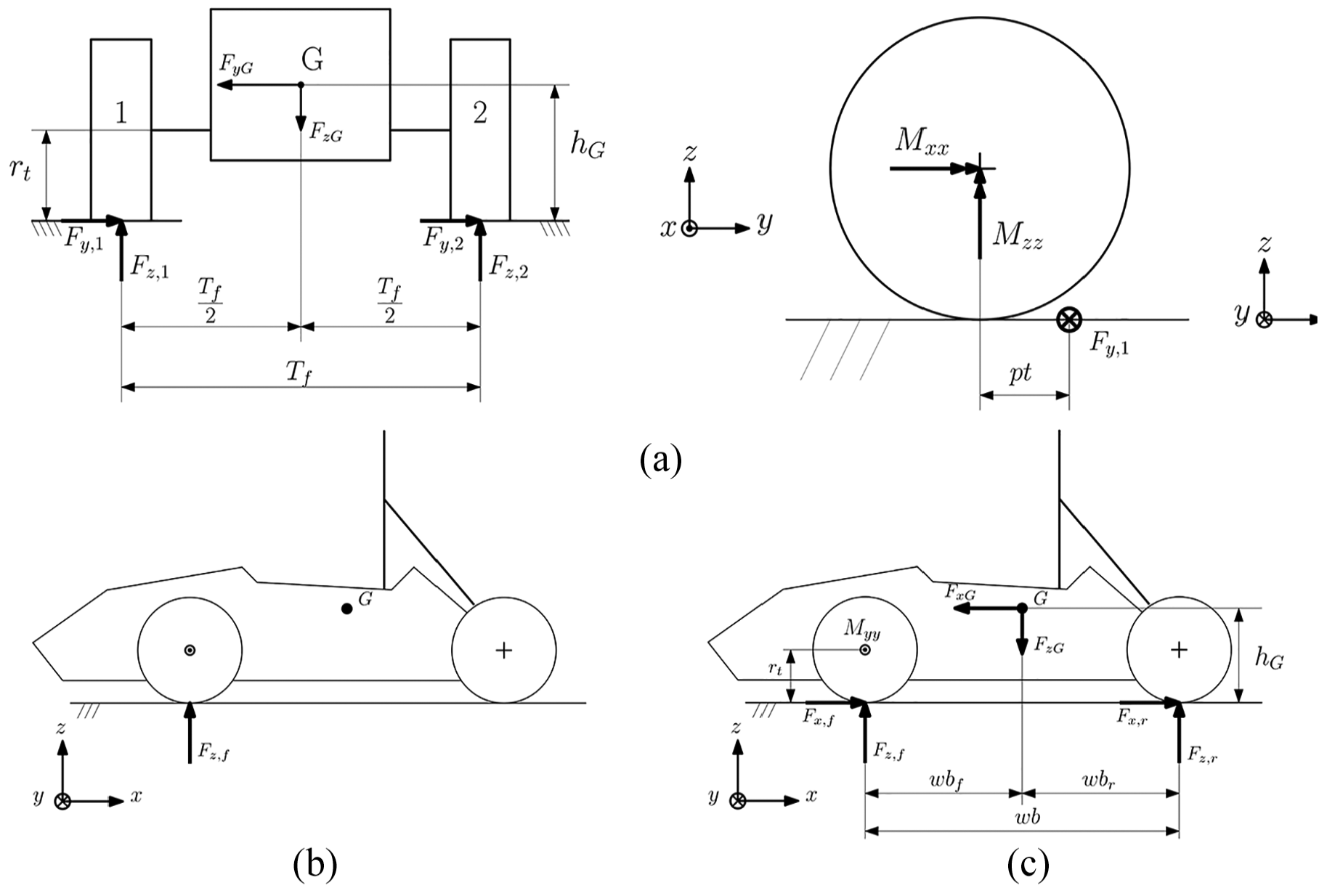
Schematic of the vehicle for different loading conditions: (a) front view (on the left) and lateral view (on the right) for the cornering case; (b) lateral view for the bumping case; and (c) lateral view for the braking case.
Mesh sensitivity study, operating condition of cornering. Displacements ux, uy, and uz (mm) and rotations θx, θy, and θz (°) for the reference upright geometry.
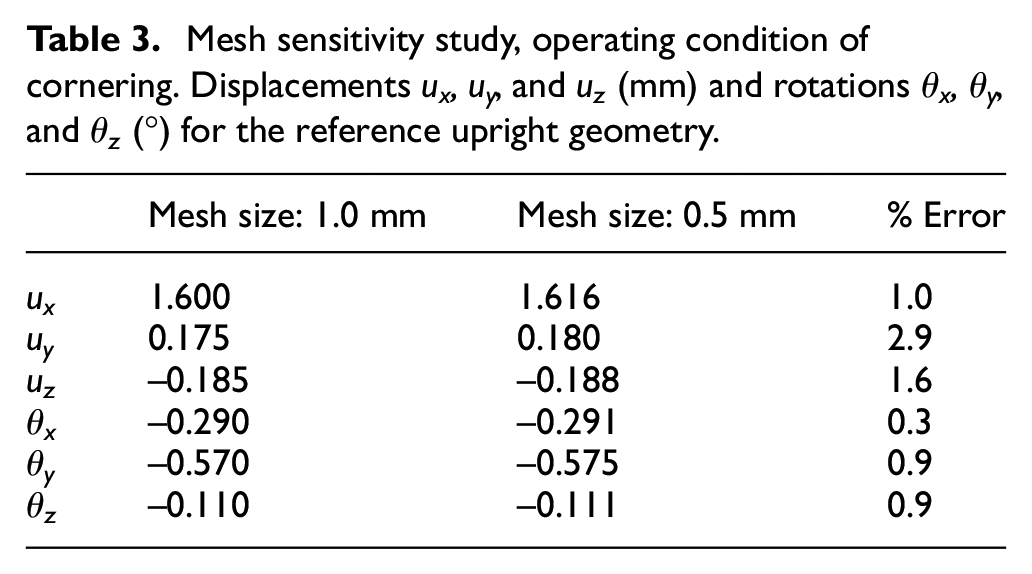
To better compare the optimization results with the reference model, the same element size of the reference will be kept for the FE optimization models. Therefore, to reduce the overall computational effort and time, the model with an average element size of 1 mm was employed as reference.
Cornering
The analysis considered the heaviest cornering condition, experienced by a left-hand side upright during a right turn (see Figure 2(a)). A maximum value of the lateral acceleration (ay) of 2.5g was registered by telemetry devices. Therefore, a lateral force (Fy,1) of 1942 N was applied to simulate the y-direction reaction force due to the tire–ground contact. Since all the loads were applied to the wheel center, it was necessary to add an x-direction transport torque (Mxx) of 443 N m to change the point of application of the force. A counter-steering z-direction torque (Mzz) of 373 N m was added to account for the pneumatic trail. Finally, a z-direction force (Fz,1) of 1794 N was applied to simulate the vertical reaction force of the tire.
Bumping
This load case aims to simulate the vehicle motion after a bump. A maximum vertical acceleration of 5.6g was considered for the bumping load case. Therefore, a z-direction force (Fz, f ) of 2564 N was applied to mimic the tire reaction force (Figure 2(b)).
Braking
The braking load case was evaluated by considering the maximum deceleration collected from the telemetry data and the mass distribution of the vehicle (Table 1, Figure 2(c)). Therefore, two forces acting along the x- and z-directions (Fx, f , Fz, f ) were applied to the front-wheel center. These forces consider the x-direction deceleration of 17.2 m/s2 of vehicle and the longitudinal load transfer. A y-direction torque of −453 N m was added as a result of Fx, f . This torque was applied by means of two forces acting on each piston of the caliper. A z-direction force of 2495 N and an x-direction force of −1019 N were applied to the upper piston of the caliper (point E). Consequently, a z-direction force of 2495 N and an x-direction force of 1019 N were applied to the lower piston (point F).
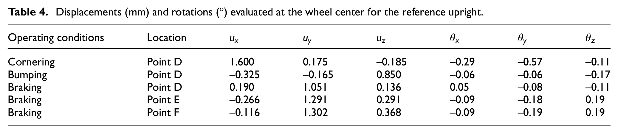
Table 4 collects the displacements and the rotations of wheel center (point D) and of the caliper pistons (points E and F) for all the load cases.
Displacements (mm) and rotations (°) evaluated at the wheel center for the reference upright.
TO model setup
TO is a robust numerical technique commonly adopted to define the optimal distribution of material within a prescribed design domain. In the automotive field, TO is usually applied to minimize a component mass under a given set of optimization constraints in a prescribed design space. Herein, the constraints threshold applied to the upright was derived from the reference aluminum geometry (Table 4), considering the cornering, bumping and braking conditions. A wide domain of the structure was defined, comprising the maximum available space. The domain was subdivided into the designable and non-designable areas as shown in Figure 3. The mating surfaces of the upright to the suspension assembly were considered as no-design elements (132,000 black elements). The designable domain was meshed with 3.95 million tetrahedral elements, and the average element size was 1 mm. The TO analysis was performed using Altair Optistruct v.13, while the model setup was built using Altair Hypermesh. A gradient-based optimization algorithm belonging to the method of feasible directions4,45 was adopted. In detail, the solid isotropic material with penalization method was applied, where the penalty factor p and the sensitivity filter r were set equal to 3 and 2, respectively. The elements with intermediate density were thus penalized to achieve a well-comprehensible loading path solution. 28 The selected design space was subjected to three optimizations, each of which considered one of the three loadcases, that is, cornering, bumping and braking. The redesign was performed by critically analyzing the results of each loading condition on the TO results, emphasizing thus the influence of the three loading conditions on the final design. To do so, the results of the three TO will be thoroughly reviewed to identify those areas to be reinterpreted with solid, shell, and beam-like structures. For any optimization, the adopted p and r values were the same, and they ensure a quick convergence of the optimization, thus limiting the maximum number of iterations.
Design domain.
Experimental data for the material card
L-PBF accomplished in the recent years a notable increase in the quality and mechanical properties of parts and is now widely used for automotive and aerospace applications.46,47 In order to ground the FE model on a solid experimental base, values for the material card have been retrieved through a two-step testing process. First, the combination of machine, powder and process parameters has been tuned and then frozen by building a validation job that included:
Five cubes built in different positions of the build platform, to be tested for Archimedes’ density, Brinell hardness (HB10 HBW2.5/62.5), and metallographic analysis;
24 tensile specimens: Eight vertical, eight horizontal and eight with a 45° slope with respect to the build platform.
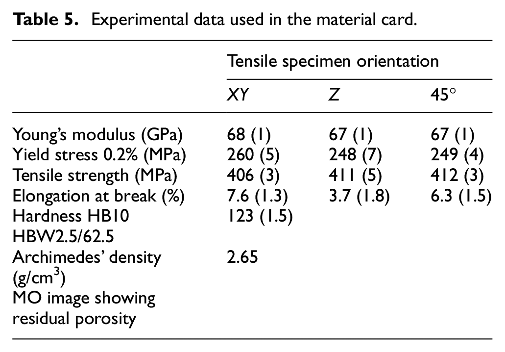
In a second step, based on the approval of the setup, one cube and two tensile specimens have been built together with the upright, during the same job. Hence, the properties achieved in a specific construction process can be validated versus the reference values. All specimens have undergone the same relief treatment as of the upright: 2 h at 190 °C. Results of these experimental steps are reported in Table 5.
Experimental data used in the material card.
TO results
At first, Figure 4 shows a detailed discussion on the trend of the objective function and the constraints violation, at any TO iteration. The mass (and the number of iterations) evaluated by the optimization process was equal to 0.344 kg (60), 0.327 kg (50) and finally 0.344 kg (80) for the cornering, the bumping and the braking loading conditions, respectively. However, the TO results need to be interpreted and a univocal feasible solution is pursued. Figure 4 presents the trend of the objective function of the optimization, that is, the component mass, for any iteration. The curves exhibit a rapid downward trend of the component mass after the first iterations and then they remain reasonably steady.
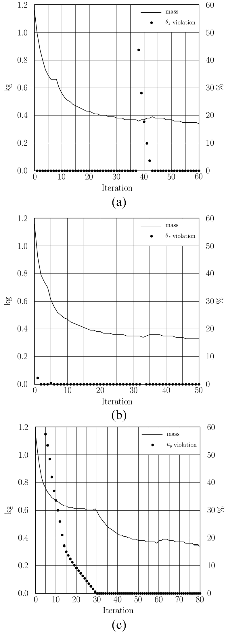
The trend of the objective function of the optimization and the percentage variance of violation of constraints for cornering (a), bumping (b), and braking (c) conditions.
In addition, Figure 4 shows the most critical constraint to be satisfied for any loadcase. The constraints are as follows: the z-rotation for the cornering and bumping loadcases; and the violation of the y-displacement for the braking analysis. The violation of these constraints is presented by the percentage variance with respect to the associated threshold summarized in Figure 4. For the bumping and the cornering, the maximum violation of the z-rotation upper bound (>40%) occurs at the 33rd and 38th iterations, respectively. The violation of the constraints occurs for a limited variation of the mass distribution of the component when the solver is just before the optimal solution. For the braking loadcase, no violation for the y-displacement is found after the 30th iteration.
The TO result is a solution where the material density of each element should be close to either 0 or 1, for void or solid areas, respectively. A proper minimum density threshold needs to be found to have a good compromise between a well-linked, neatly defined structure and a light structure with slender features. Therefore, in the present test case, the minimum threshold density was set equal to 0.4.
Figure 5 displays the map of relative densities above the given threshold. Nevertheless, the TO results do not provide a ready-to-use geometry of the component and a manual reinterpretation is required. A discussion on the density contour maps and the design reinterpretation is presented for the new upright.
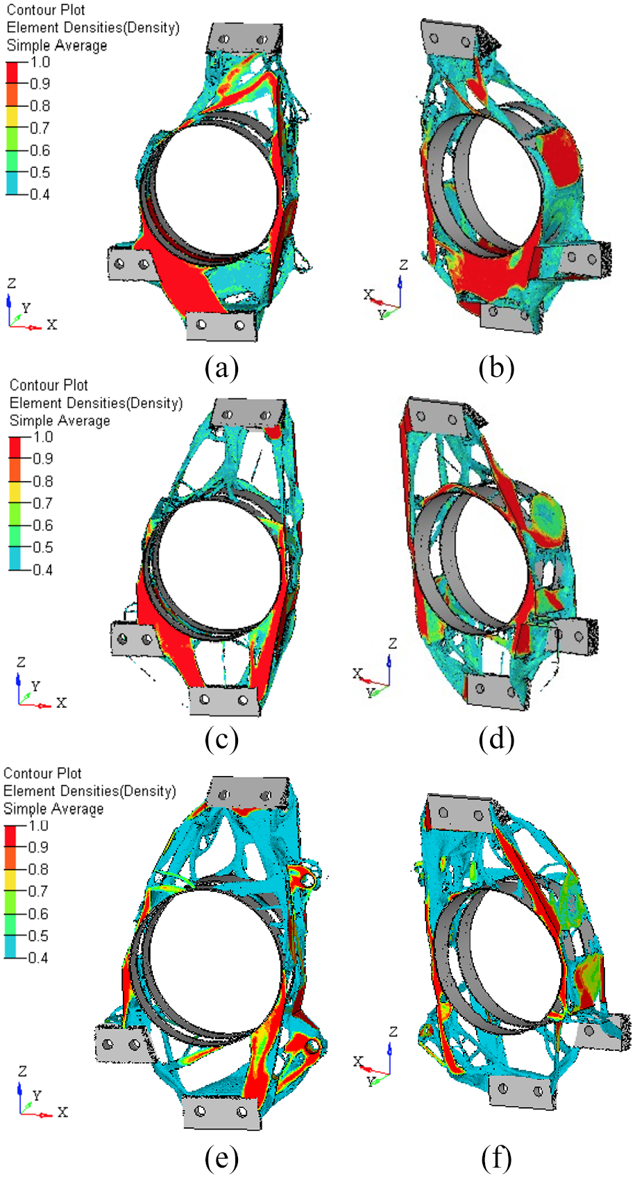
TO results for the cornering (a, b), bumping (c, d), and braking (e, f) conditions.
The cornering condition in Figure 5 (a) and (b) results into the most burdensome density distribution of the three. If the rear of the design domain is considered in Figure 5(b), solid elements are mainly required at its bottom region, to link laterally the lower wishbone anchor points to the bearing seats. A further massive rib, linking the tie-rod anchor point to the connection with the lower wishbone mounting bracket, is evident. Furthermore, the two bearing seat locations are joined transversally via solid elements (y-direction) coherent with the vehicle track direction for three-quarters of their circumferential extent. Moving from the bottom to the upper region of the design domain, the TO results show a tangled response that is particularly difficult to reinterpret. As a first approximation, the TO results for the cornering condition might be modeled by thin plate components, but this design solution might not be self-supporting when produced by L-PBF.
The TO results for the bumping load case in Figure 5(c) and (d) point out well-defined and triangulated structures. In fact, the elements with the highest density are located in the lateral areas of the design domain that join the wishbone anchor points to the bearing seats. The bumping load case can be rationalized by considering the component equivalent to a beam with a generic cross section. The simply supported beam lies in the xz-plane and is subject to a concentrated force acting at its center along the x-direction. The bending stress increases away from the neutral axis and therefore the beam cross section should be reinforced at its extremities. The TO results for the bumping condition reflect this engineering perspective, if the three-dimensional nature of the problem under scrutiny is considered. In fact, two lateral ribs link the upper to the lower no-design domains related to the wishbone, closing in on the bearing seats.
The TO results for the braking load case (Figure 5(e) and (f)) reveal a triangulated solution as already seen for the bumping. However, in this case, the ribs not completely connected within the design domain if the density contour plot is cut at 0.4. The main loading paths with the highest density are located at the lower support of the caliper and at the lower wishbone joint. A further high-density volume connects the rear bearing seats and the upper wishbone joint (see Figure 5(f)). These two volumes can be, respectively, modeled via solid cross-section beams.
Preliminary redesign of the steering upright for AM
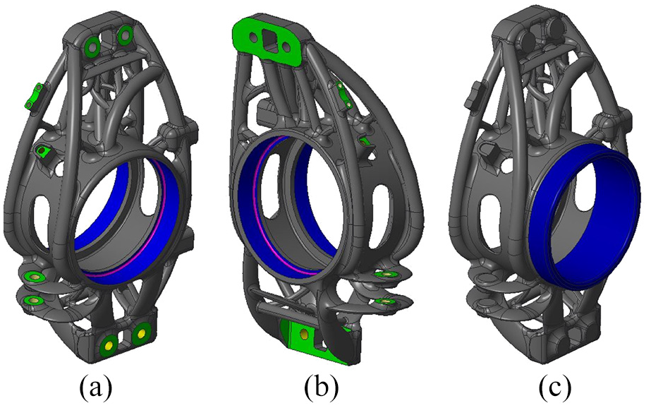
At the light of the TO results and the previous discussion, the redesign of the component is presented in Figure 6. In fact, due to the freedom of AM process, the final shape of the upright becomes more adherent to the TO results. Furthermore, the minimization of supports was pursued during the redesign phase. The geometry of the bearing seats, of the interface with the wishbone and the tie-rod were unchanged with respect to the original component, to allow the new upright to fit the original suspension system. Furthermore, based on the previous results, radial-mount brake calipers were introduced instead of the previous axial mount. This solution was adopted to stiffen the upright-caliper assembly, consequently increasing the driveability of the vehicle. The location of the bolted connection between the brake caliper and the upright was modified accordingly (Figure 6(c)).
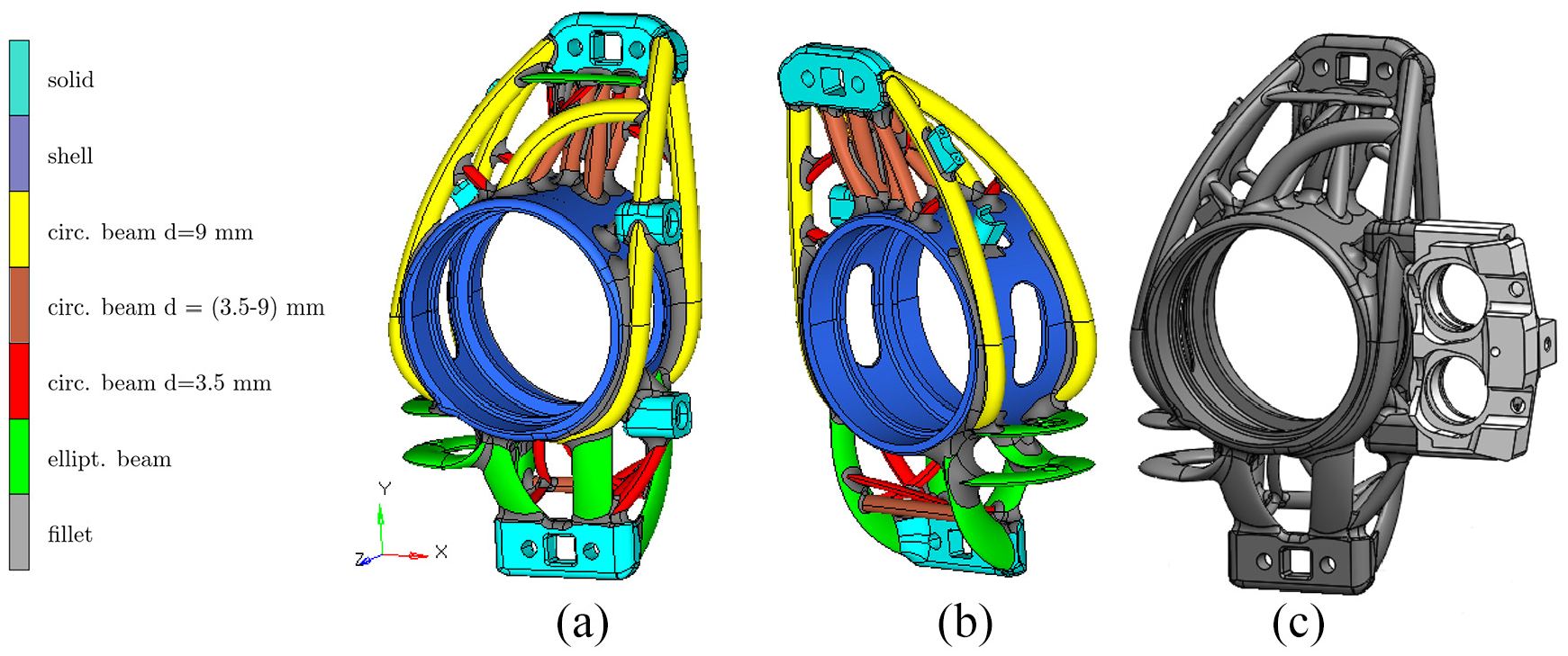
Redesign of the upright: (a) front, (b) rear, and (c) assembly.
The integration of the tie-rod non-design domain into the redesign process, as well as the hollowing of both the wishbone anchor points, represent interesting possibilities to further lightweight the upright.
Two additional solid features were introduced at the upper rear side of the upright to mount the speed sensor of the wheel. These features were not included in the TO analysis, because the sensor does not induce any relevant load in the upright.
The new design of the upright coped with the TO load paths through solid structure, shell and curved beam-like structures (see Figure 6). In fact, the wishbone bases and the caliper supports are modeled as solid regions. The thickness of the wishbone bases on the y-direction is 8 mm. The caliper mount has a squared cross section of 15 mm, with an x-extent of 21 mm.
The bearing seats are modeled by shell structure. Their radial thickness is 4 mm. According to the cornering results, two symmetrical circumferential grooves (gap = 16 mm) were adopted to further decrease the component weight. Their circumferential extent is equal to 130°.
Finally, beam-like structures were applied to link the wishbone bases and the bearing seats, according to the TO results of the bumping and braking load cases (Figure 6(a)). The trabecular structure linking the tie-rod support to the bearing seats in Figure 6(b) was designed specifically to address the TO load paths of the cornering load case.
At the upper wishbone joint, the beams have a circular solid cross section. Their diameter ranges from 9.0 to 3.5 mm. The thickest beams are located at the outer regions where the higher element densities are found. At the lower wishbone joint, beams with elliptical cross section were modeled. This design choice descends from the TO results of bumping (Figure 5(c)). Their aspect ratio (dmax/dmin) ranges from 2 to 3. At the rear side of the upright, close to the lower wishbone connection, an X-beam distribution was adopted to approximate the cornering TO outcomes. Their solid cross section is circular with a mean diameter of 3.5 mm. Once again, the connection between the tie-rod and the upright was reinterpreted by curved members with an elliptical cross section (dmax/dmin = 3). The transition zones between beams, shell and solid were tuned with fillets with radii ranging between 3 and 9 mm. The fillets decrease the onset of stress concentration, typical of these connection zones. This design choice is commonly adopted during the engineering practice to prevent failures.48–50 The new upright weighs 400 g, with a mass reduction of 9% over the reference component. The final size of the component is 200, 55 and 113 mm along the x, y and z directions, respectively.
FE validation
Once the final geometry of the upright had been defined, FE analyses were performed to verify the accomplishment of the structural targets for the new upright. Furthermore, its integrity was investigated at the stress peak values and under Euler buckling. The FE program MSC Marc2013.1 was employed in these calculations.
The mesh included about 735,000 isoparametric elements, with 155,000 pentahedral elements and 580,000 tetrahedral elements. The average element size was 1 mm. The rigid body elements (RBE2 and RBE3) and the boundary conditions were the same applied in the TO analysis.
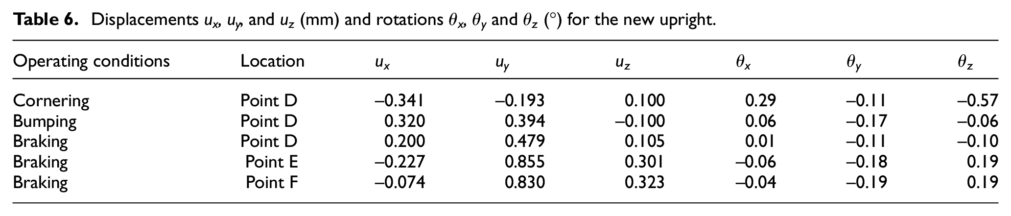
The upright and the brake caliper were modeled in aluminum, and the bolted connections were in steel. The displacements and rotations collected at the wheel center of the assembly system are listed in Table 6. The new component achieves the structural performance of the reference one. In the cornering and braking loading conditions, the x- and y-direction displacements at the wheel center exceed the reference values by 5%. However, this pliant behavior is considered acceptable for this application.
Displacements ux, uy, and uz (mm) and rotations θx, θy and θz (°) for the new upright.
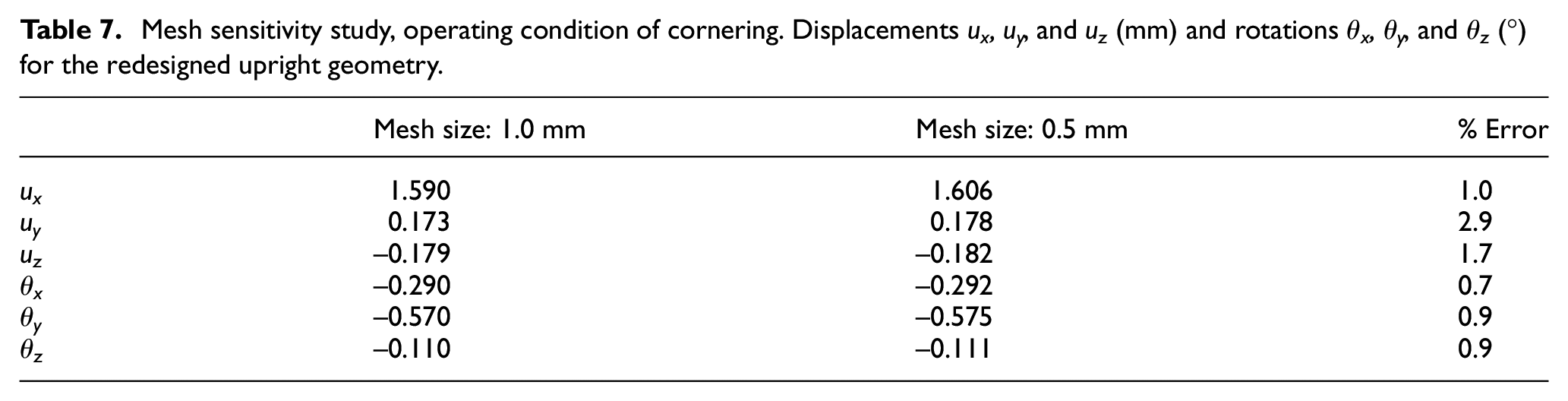
As to Euler buckling, the slender rib of material that connects transversally the bearing seats represents the most critical region (Figure 7(a)). However, under the bumping (cornering) loading condition, the first buckle mode occurs at 202 kN (266 kN), which is a lord value 92 (126) times higher than the operating racing conditions. For the braking condition, the FE analysis indicates that the beams are mainly under tensile stresses and therefore buckling is avoided. The maximum von Mises equivalent stress within the upright takes place at the upper wishbone bolted connections for the bumping load case; the maximum stress is 130 MPa (Figure 7(b)). However, the safety margin is equal to 2. It might be concluded that the new upright design constitutes a good compromise between lightness and structural performance. A sensitivity analysis of the mesh has been performed also for this new upright. Table 7 shows the results of the displacement collected at the wheel center for the cornering loading condition. The error is evaluated with respect to the model with 1.0 mm element size, and it remains lower than 3%. The results of the bumping and braking loading conditions fit the trend already discussed for the cornering loading condition, and they have been omitted for brevity.
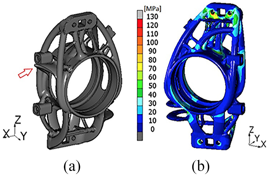
Buckling mode occurring during bumping: (a) deformations (amplitude factor = 2000) and (b) equivalent von Mises stresses.
Mesh sensitivity study, operating condition of cornering. Displacements ux, uy, and uz (mm) and rotations θx, θy, and θz (°) for the redesigned upright geometry.
Industrialization
After structural validation, the part geometry was further modified according to DfF to facilitate the clamping operations. In particular, the ring-shaped appendix (blue in Figure 8(c)) was added around the central hole to ease mounting upon turning the ball bearing seats. Thus, two diameters can be machined in one placement to reduce time and cost.
DfF modifications.
The industrialization of the modified part was carried out in Materialize Magics by planning the production with AlSi10Mg on an SLM 280HL machine.
The part orientation on the base platform was optimized according to three principles:
Thermal stresses were minimized by smoothing the cross sectional changes along the build direction, because sudden variations are known to engender local heat accumulations and sharp thermal gradients.51,52
Support structures were minimized; the self-supporting angle was set at 35°, which ensured the geometry feasibility but potentially lowered the surface finish. 53
Surfaces not to be machined after manufacturing were oriented so that the staircase effect was minimized. 54
After fixing the part orientation, solid structures (red in Figure 9) were designed directly within the computer-aided design (CAD) environment to cut down the support material, to facilitate the powder removal and to speed up the part finishing.
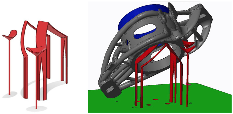
CAD-modeled solid supports.
Complete support structures were created back in Magics. The total volume of supports, including 80% block, 15% pin and 5% line structures, was 27,908 mm3.
Two industrialized parts were nested on the same platform (Figure 10) together with the tensile and density test specimens required to certify the job. Manufacturing took 14 h.
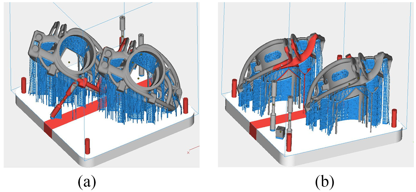
Nesting of the industrialized parts on the build platform.
The uprights were stress relieved at 190 °C for 2 h, while still connected to their support structures (Figure 11).
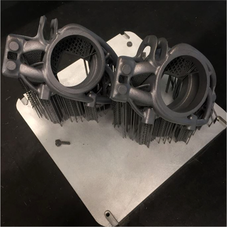
The printed uprights.
Conclusion
In this article, a numerical methodology for designing automotive components was presented by considering the AM technique. In particular, the case-study of a front steering upright has been addressed. The adoption of AM coupled with TO represents a challenging opportunity for a lightened solution. This article offers guidelines for the interpretation of structural features in the resulting relative density contour plots. For instance, a wireframe of beams was favored to connect the upper and lower double-wishbone joints to the bearing seats, instead of the adoption of thin plates. This design solution allows the component to be more self-supporting when produced by L-PBF. Bulk materials were used at the non-design areas close to the bolted connections. The final mass of the redesigned part was 400 g, thus leading to a 9% weight reduction over the reference CNC component. After optimizing the part orientation and the support structures, the part was produced in AlSi10Mg and stress relieved by thermal treatment.
Further dynamic modal analyses are planned to ascertain that the new upright does not significantly affect the noise, vibration and harshness map of the vehicle (see Azadi et al. 55 and Rotondella et al. 56 ). Further validation tests will be performed on the prototypes presented above, to measure the displacements at the crucial points of the uprights. The tests will include a dedicated test-rig to properly mimic the three loadcases.
Footnotes
Declaration of conflicting interests
The author(s) declared no potential conflicts of interest with respect to the research, authorship, and/or publication of this article.
Funding
The author(s) disclosed receipt of the following financial support for the research, authorship, and/or publication of this article: This work was supported by the Regione Emilia Romagna (Italy), under POR-FESR 2014-2020 Actions 1.1.1 and 1.1.4 L.R. 14/2014 grant number E98I17000090009.