
Abstract
In this work, a novel grinding method using a special abrasive tool was first proposed to achieve high tangential grinding force and low normal grinding force. The abrasive tool was developed with flexible composites to remove workpiece materials under “high-shear and low-pressure” grinding mode. The concept of the high-shear and low-pressure grinding method was introduced in detail. Grinding tests were carried out on a precision grinder with the developed abrasive tool for single crystal silicon specimens. The results showed that the grinding force ratio between tangential force and normal force for the proposed grinding method was ranged between 0.9 and 1.3, which was three times larger than that of the conventional grinding method. It was verified that the developed abrasive tool possessed the grinding characteristics of high tangential grinding force and low normal grinding force. After grinding of silicon specimens for 120 min, the value of surface roughness decreased from 429.20 to 32.91 nm under the selected grinding conditions. The surface quality of the silicon specimens was greatly improved after grinding.
Keywords
Introduction
Grinding is one of the most widely used high-efficiency precision machining technologies in manufacturing industries. It especially provides an important solution for the creation of high-precision surfaces for difficult-to-machine materials.1–3 However, there remain machining issues such as low material removal rate, grinding wheel clogging and poor surface integrity in the grinding of difficult-to-machine materials. According to the grinding mechanism, these issues are mainly attributed to the large normal grinding force and the small tangential grinding force in the grinding process.4–8 The ratio of normal grinding force to tangential grinding force is approximately three (i.e. frictional coefficient is ∼1/3) in the conventional grinding. For some difficult-to-machine materials (e.g. hard-brittle materials), the energy required is quite huge during grinding. Hence, the ratio of normal force to tangential force is several times or even tens to hundreds of times larger than that for the grinding of ordinary materials.6–8 This leads to more severe grinding issues for difficult-to-machine materials.
As the grinding force plays an influential role in material removal and grinding quality, the investigation regarding grinding force is a hot research topic in the field of grinding technology.6,7 Great efforts have been made to develop the theoretical model which is able to predict the grinding force under different grinding conditions and reduce the impact of the grinding force on the grinding quality.8–10 Chang and Wang 11 established a stochastic grinding force model considering random grit distribution. The spectrum characteristics of the grinding force were investigated in the frequency domain. The theory determined the law of the influence of abrasive particle distribution on grinding force. Wang et al. 12 investigated a novel grinding force model based on grain–workpiece contact and the analyses of grain trajectory. The validity of the grinding force model was validated via grinding experiments. Zhou et al. 13 proposed a genetic algorithm based on the back-propagation neural network (BP) model and optimizing back-propagation neural network (GABP) model. The prediction and evaluation of titanium alloy grinding force is realized during the creep-feed grinding.
Meanwhile, advanced grinding methods and processing techniques (e.g. intermittent grinding,14,15 high-efficiency deep grinding (HEDG),16,17 chemo-mechanical grinding (CMG) 18 and ultrasonic vibration–aided grinding (UAG)) 19 were investigated to mitigate the current grinding issue and improve the grinding performance. Tawakoli and Azarhoushang 14 investigated the intermittent grinding processes of ceramic matrix composites. The grinding wheel wear and grinding forces were effectively reduced. Material removal rate and surface integrity had been significantly improved. Li et al. 16 conducted HEDG experiments for Inconel 718. The main wear behavior of the abrasive tool and the energy partitioning into the ground workpiece were determined and analyzed. Tian et al. 18 investigated material removal mechanism in CMG of Si wafers. The grinding characteristics and the topography variations of workpiece surface during CMG process were explored. Wang et al. 19 established a theoretical model for system matching in UAG of brittle materials to reveal the mechanism of surface generation and force reduction.
However, current studies on the theoretical model of grinding force and investigation of the advanced grinding method and technique are still unable to change the fact of large normal grinding force and low tangential grinding force during grinding. Few studies are focused on how to reduce the grinding force and the ratio of the normal force to the tangential force in the grinding process. Therefore, it is of great significance to find a new way to overcome the conventional grinding issues.
In this work, a novel machining concept called “high-shear and low-pressure grinding” was first proposed with a special abrasive tool with aim to improve tangential grinding force and reduce normal grinding force during grinding process. The tool was fabricated with flexible composite, that is, warp-knitted spacer fabric was impregnated by micro/nano abrasive mixed shear thickening fluid (STF).
Concept of high-shear and low-pressure grinding
The initial concept was originated from liquid body armor and the shear thickening mechanism of non-Newtonian fluid. The liquid body armor is made from STF and high-performance fibers. The viscosity of the STF sharply increases with the increase in the shear rate. Under the condition of impacts, the STF is able to change from liquids to semisolids instantly as a typical non-Newtonian fluid. In recent years, the STF has been applied in the novel loose abrasive machining such as shear thickening polishing 20 and magnetic shear thickening finishing. 21 Similar concept was proposed to apply in the fixed abrasive machining to achieve the high-shear and low-pressure grinding. The abrasive tool was developed with flexible composite, that is, warp-knitted spacer fabric and STF. During grinding, abrasive particles of the developed flexible composite tool were capable of generating the “hydro-cluster effects” under reverse tangential load, which led to the decreased normal grinding force and the increased tangential grinding force. Hence, workpiece materials were removed under “high-shear and low-pressure” grinding mode.
The composition of the abrasive tool consisted of dispersion medium, dispersed phase, high-performance fibers, abrasive particles and additives, as shown in Figure 1.
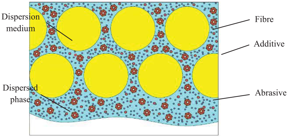
Schematic diagram of composition of the novel abrasive tool.
As illustrated in Figure 2, the material removal mechanism of the high-shear and low-pressure grinding method is explained in the four following stages: 22
In stage 1, as shown in Figure 2(a). The novel abrasive tool and workpiece surface come into mechanical contact. At this moment, abrasive particles are uniformly distributed in the novel abrasive tool.
In stage 2, as shown in Figure 2(b). In the contact interface, collision and extrusion occur between the abrasives and the surface micro-convex peaks of workpiece. The large reverse tangential load was generated on the abrasives instantaneously under high relative speed mode. Meanwhile, abrasive particles and dispersed phase gather together and aggregate into “particle clusters.” The apparent viscosity around the loaded abrasive particles increases sharply and reaches a stable value in a very short time. It leads to the increased tangential force and decreased normal force.
In stage 3, as shown in Figure 2(c). When the acting force of “particle clusters” exceeds the material removal critical yield stress, the abrasive particles will remove the top of the micro-convex peaks of the workpiece surface. At this point, the reverse tangential load disappears instantly. The apparent viscosity around the original abrasives will simultaneously decrease and returns to its initial status.
In stage 4, as shown in Figure 2(d). When materials of the top of the micro-convex peaks are removed, the reverse tangential load on the abrasive particles disappears instantly. And abrasive particle, dispersed phases and dispersion medium resume initial configuration. Hence, abrasives and dispersed phases go back original state in the novel abrasive tool.
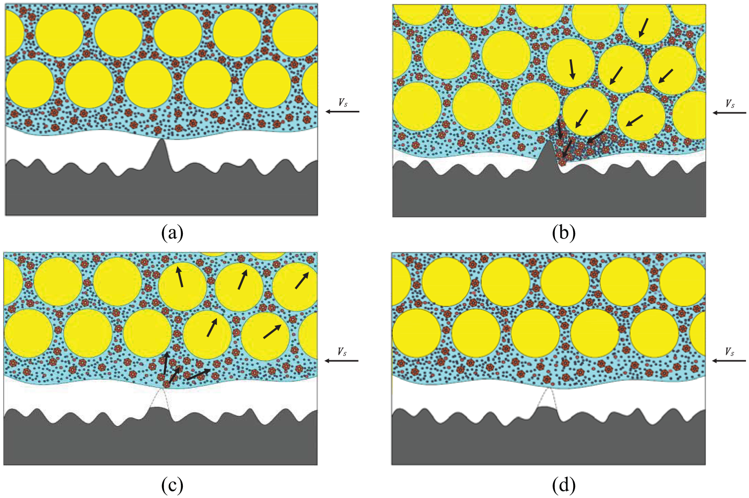
Microscopic diagram of high-shear and low-pressure grinding principle: (a) initial stage, (b) contact stage, (c) material removal stage, and (d) recovery stage.
Experiments and discussion
In order to verify the concept of high-shear and low-pressure grinding, the novel abrasive tool was fabricated in the lab. According to the previous studies,23,24 the STF of SiO2/polyethylene glycol (PEG) system possesses excellent shear thickening characteristics and the stable properties. It is suitable as the main components for the fabrication of the novel abrasive tools. In addition, the content of nano-scale silica is much lower than that of micro-scale silica in the STF to achieve better shear thickening effects. Kevlar fiber is used as one of the most matured fabric materials in the field of fabrication of liquid body armor. Therefore, silica nanospheres (SiO2) with an average diameter of 50 nm were selected as the abrasive and the dispersed phase. Polyethylene glycol (PEG200) was employed as the dispersion medium. The high-performance fibers Kevlar 29 were woven into flexible plain fabrics (1500 denier, 22.5 yarn per inch). The silica nanospheres (50 nm SiO2) with a fraction of 23 wt% were mixed with the PEG200 through mechanical agitation in combination with ultrasonic dispersion at the temperature of 60 °C to prepare the STF. The abrasive mixed STF (SiO2 (23 wt%)/PEG200) was impregnated into the plain fabrics to make the flexible composite. The novel abrasive tool was fabricated by bonding the flexible composite to a mental substrate.
Figure 3 shows the scanning electron microscope (SEM) images of the fabrics before and after impregnation with the abrasive mixed STF, that is, 50 nm SiO2 (23 wt%)/PEG200. It could be found that there were no any abrasive particles except a little contamination on the neat fabrics without impregnation of abrasive mixed STF, as shown in Figure 3(a). However, in the impregnated fabrics, as shown in Figure 3(b), a huge number of SiO2 particles evenly covered on the surface of the fabrics filaments. It was also observed that the particles were completely filled up the gap of the fabric filaments.
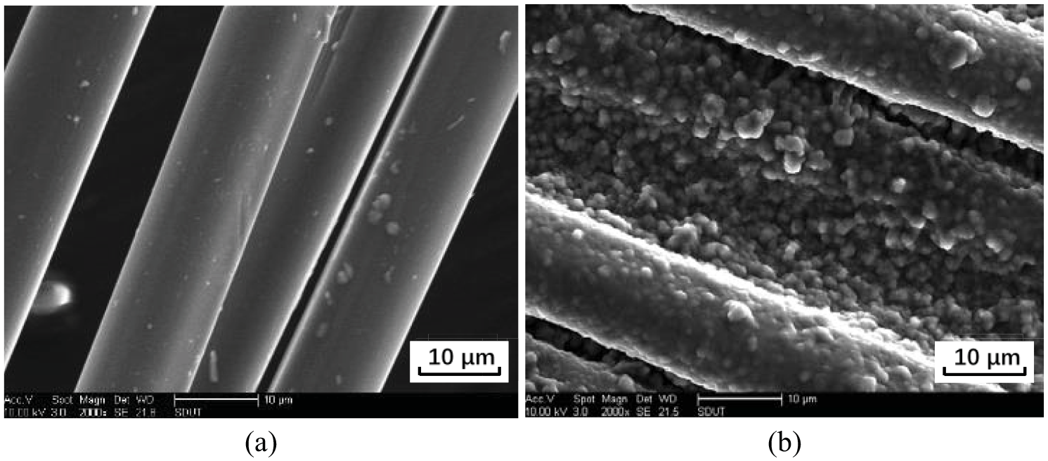
SEM images of fabrics before and after impregnation of abrasive mixed STF.
Grinding tests were carried out with the developed novel abrasive tools on single crystal silicon specimens using a three-axis precision grinding machine (SMART-B818III). Piezoelectric dynamometer (Kistler 9257B) was used to measure the grinding force during grinding. The detailed experimental setup was shown in Figure 4. The grinding parameters were selected according to the previous experiments as listed in Table 1. The surface roughness of the ground silicon specimens was measured with MicroXAM-100 white light interferometer. Field emission scanning electron microscope (FE-SEM Sirion200) was employed to observe the surface topography of ground silicon specimens.
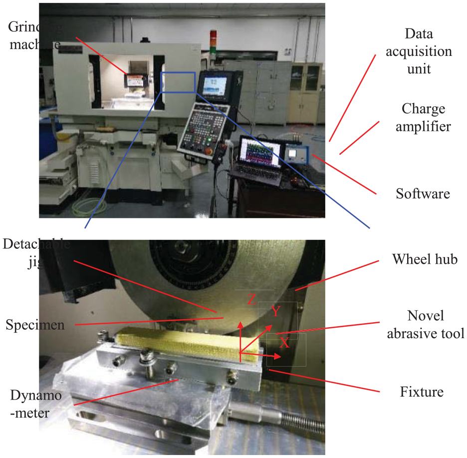
Experimental setup.
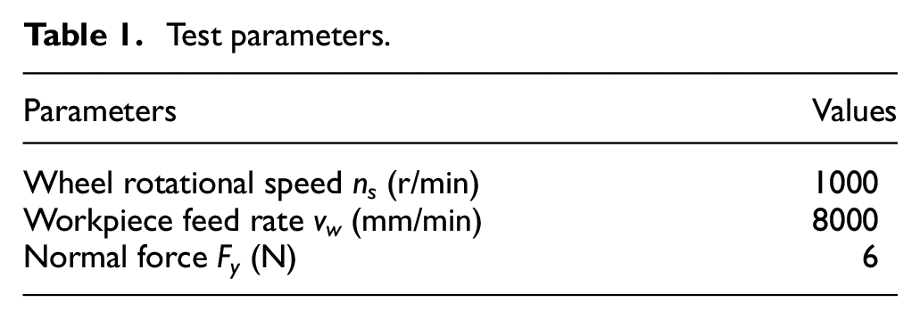
Test parameters.
In the grinding experiment setup, the specimen was bonded to a detachable jig with special glue. The detachable platform was installed on a 200 mm disk substrate in diameter. After the dynamic balancing of the disk substrate with the single crystal silicon specimen, it was installed on the grinding machine spindle through the wheel hub as shown in Figure 4. The novel abrasive tool was fabricated by bonding the flexible composite to a rectangular 304 steel substrate. The basic size of the abrasive tool is 150 mm × 30 mm × 30 mm. The grinding tool was installed on the piezoelectric dynamometer with a special fixture.
Grinding force Fy in the y-axis direction measured was approximately equal to the normal grinding force Fn, and the force Fx in the x-axis direction measured is approximately equal to the tangential grinding force Ft. When grinding of silicon specimens, the grinding force ratio Fx/Fy of the neat Kevlar 29 fabrics was ranged between 0.30 and 0.45, which was in line with the grinding force ratio in the conventional grinding process. As shown in Figure 5(a), when ns = 1000 r/min, Fy = 6 N and vw = 8000 mm/min, the grinding force ratio Fx/Fy of the neat Kevlar 29 fabrics was about 0.357. Under the same machining parameters, the grinding force ratio Fx/Fy of the novel abrasive tool was up to about 1.055 as shown in Figure 5(b). It was found that the grinding force ratio Fx/Fy was about three times larger than that with the neat Kevlar 29 fabrics. This indicated the addition of the abrasive mixed STF increased the friction between the novel abrasive tool and the silicon specimens. When the micro-convex peaks of the surface of the silicon specimen impacted the novel abrasive tool at high speed, shear thickening effect occurred due to the large shear stress and shear rate. The viscosity of the STF sharply increases with the increase in the shear rate. The STF changed from liquids to semisolids or solids instantly, which increased the ratio of the tangential grinding force to the normal grinding force. It was verified that the developed novel abrasive tool possessed the grinding characteristics of high tangential force and low normal force under the selected test conditions.
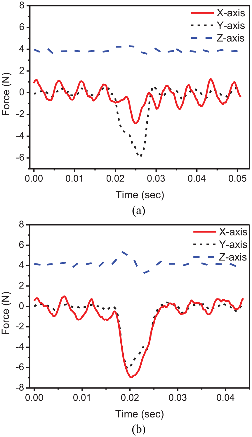
Grinding force ratio (Fx/Fy) with neat Kevlar 29 fabrics and novel abrasive tool: (a) neat Kevlar 29 fabrics (Fx/Fy = 0.357) and (b) novel abrasive tool (Fx/Fy = 1.055).
Figure 6 shows the variation of surface roughness of the ground silicon specimens with processing time. It can be found the surface roughness rapidly decreased in the first 30 min of grinding. The original surface roughness was 429.20 nm before grinding. It became 94.09 nm in the first 10 min. Surface roughness was improved by approximately 78%. It reduced to 54.07 nm at 30 min of grinding. Afterward, it changed very slowly. The surface roughness decreased to 37.58 nm after 60 min of grinding. It reached 32.91 nm after grinding proceeded for 120 min. The fact suggests that the decreasing rate of surface roughness value was large at the beginning of the grinding process while it reduced rapidly as the ground surface became smooth. According to the illustration shown in Figure 2, the initial surface of the specimen was rough before processing to a certain extent, and the effects of shear thickening were aggressive. Hence, the materials were removed rapidly with the abrasive tool. However, as the surface of the specimen became smooth, the impacts between the abrasive tool and the specimen gradually weakened. This caused the material removal gradually slow down.
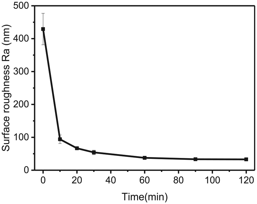
Variation of surface roughness with processing time.
Figure 7 exhibits the comparison of three-dimensional (3D) topography on silicon specimen surface observed with white light interferometer before and after grinding test. The surface of the as-received silicon specimens was roughly ground with #325 diamond wheel. There existed obvious grinding texture on the silicon surface as shown in Figure 7(a). After grinding for 120 min, the surface texture became shallow and no extra defects were introduced during the machining process as shown in Figure 7(b). Figure 8 shows the SEM images of silicon specimens before and after grinding. There were severe surface defects such as scratches, pits and orange peels on the surface of the as-received silicon specimen as shown in Figure 8(a). After 120 min of grinding, the original defects had been removed except the deep residual pits as shown in Figure 8(b) and (c). Normal grinding texture and slight ductile scratches without brittle defects were observed on the ground silicon surface. The ductile scratches were formed by SiO2 clusters plowing on silicon surface as shown in Figure 8(c).
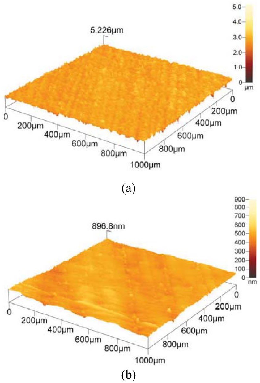
3D topography of silicon specimens before and after grinding: (a) before grinding (Ra = 429.2 nm) and (b) after grinding (Ra = 32.91 nm).
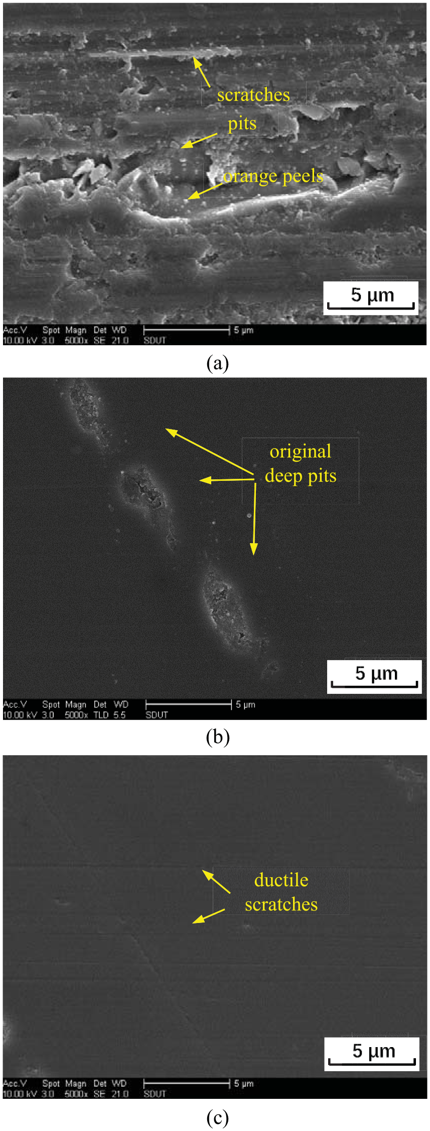
SEM images of silicon specimens before and after grinding: (a) as-received specimens and (b) and (c) after grinding.
Conclusion
In summary, this article presented a novel high-shear and low-pressure grinding method using specially developed abrasive tools made of SiO2/PEG200 flexible composites. During grinding, abrasive particles are capable of generating a “cluster effects” under reverse tangential load, which lead to the decreased normal grinding force and the increased tangential grinding force. Hence, workpiece materials are removed under “high-shear and low-pressure” grinding mode. The grinding test results show that the grinding force ratio Fx/Fy of the novel abrasive tool was ranged between 0.90 and 1.30 during grinding the silicon specimens. It was verified that the novel abrasive tool possessed the grinding characteristics of high tangential force and low normal force. The surface roughness of the ground silicon specimen was improved from initial 429.20 to 32.91 nm. Ground surface was greatly improved and no extra brittle defects were generated on the specimen surface after grinding with the novel abrasive tool.
Footnotes
Declaration of conflicting interests
The author(s) declared no potential conflicts of interest with respect to the research, authorship, and/or publication of this article.
Funding
The author(s) disclosed receipt of the following financial support for the research, authorship, and/or publication of this article: This research was financially supported by the National Natural Science Foundation of China (grant no. 51905322), the Taishan Scholar Special Foundation of Shandong Province (grant no. tsqn201812064), the Scientific Innovation Project for Young Scientists in Shandong Provincial Universities (grant no. 2019KJB030), the Shandong Provincial Natural Science Foundation (grant no. ZR2017MEE050), the Shandong Provincial Key Research and Development Project (grant no. 2018GGX103008) and the Key Research and Development Project of Zibo City, China (grant no. 2019ZBXC070).