
Abstract
Sustainability assessment is becoming an unquestionable issue for manufacturing companies that are urged by governments and customers to provide environment-friendly products. Machining, as one of the major manufacturing operations, has high potential factors regarding the environmental impacts of production system. Nevertheless, environmental assessments are mainly done post-product design and post-machining processes design. Integrating environmental assessment in the machining processes design could lead to significant improvements in sustainable manufacturing field. Major difficulties to perform such an assessment are the availability of the machining data and the lack of calculation rules to express them in terms of environmental impacts. This article presents a new approach based on the STandard for the Exchange of Product model data—compliant Numerical Control to integrate the machining environmental assessment in the earlier design phases. It proposes to establish cognitive links between the machining data included in STandard for the Exchange of Product model data—compliant Numerical Control and environmental indicators. The approach is implemented on a demonstrator and validated by a use case.
Introduction
Regulations on integrated product policy, 1 integrated pollution prevention and control, 2 and also high-energy prices have been identified as potential sources of motivation on reducing energy consumption and pollutions within manufacturing companies. Industries are confronted with the challenge of designing both sustainable products and sustainable manufacturing processes. Up to now, the sustainable manufacturing actions have been systematically conducted with a focus on reducing the production lead time and costs, all which in turn may lead to a reduction in energy consumption. In addition, environmental assessments are carried out beyond the product design (computer-aided design (CAD)) and the manufacturing process engineering (computer-aided manufacturing (CAM)). Thus, they are not yet integrated into the manufacturing process, and this post-design environmental consideration even lead to solutions which are increasing production costs. 3 Integrating environmental aspects earlier in the product design and its manufacturing process engineering is a promising approach to set up a new model for sustainable manufacturing. In this integrated approach, the environment will no longer be an additional constraint, but an opportunity that will allow (1) identifying new characteristics of the product and its manufacturing process likely to improve its overall perceived quality and (2) creating a market differentiation and thus a financial gain.
The environmental impacts of the production system are evaluated from the consumption and emissions caused by the use of various energy sources, materials, and consumables needed to run the production facilities. Machining is a major manufacturing operation which has potential factors for environmental impacts generation. These factors are mainly the use of noble materials for the cutting tool, the usage of lubricants, the chips generation, and the energy consumption. Therefore, the analysis of inputs and outputs from machining systems has significant implication for sustainable manufacturing. However, it has been observed that there does not exist a tangible relationship between cutting parameters and environmental impacts.4,5
This article reports on a research work which stands for integrating environmental assessment in the CAD/CAM/computer numerical control (CNC) systems based on the STandard for the Exchange of Product model data—compliant Numerical Control (STEP-NC) standard. STEP-NC is an ISO standard 6 to create machining programs that can be shared between many entities for enabling a continuous numerical integration. This work is part of the French Fonds Unique Interministériel (FUI) project called ANGEL (Atelier Numérique coGnitif intEropérable et agiLe) that focuses on the capitalization and exploitation of machining knowledge in order to improve the competitiveness of companies. The sustainable manufacturing approach proposed in ANGEL focuses on the machining operation and aims to help the CAM programmers in the choice of tools and cutting conditions. The main objective is to provide the ecological optimization of machining processes.
Section “Research background” presents a literature survey of relevant sustainable manufacturing techniques. In section “CAD/CAM/CNC systems including environmental assessment,” the proposal of the article is presented by introducing first the STEP-NC standard data structure. Second, the development of the dynamic environmental assessment method is detailed. Section “Test case for eco-assessment of manufacturing operations” illustrates the new proposition with a case study dealing with a workpiece simulation on the demonstrator. Section “Discussion” provides a discussion about the benefits and the limits of this proposition regarding the existing approaches. This article ends with the summary of the research work findings.
Research background
Over the past four decades, the environmental burdens due to industrial activities became a global and increasingly important problem and are currently a great societal challenge.7,8 The concept of sustainable manufacturing was transformed into various Anglo-Saxon labels (for instance, environmentally conscious manufacturing and green manufacturing). This section is devoted to the review of relevant methods for sustainable manufacturing in order to identify the nature of their concepts and to clarify the environmental indicators they use.
The simulation of a production system is initially based on the discrete event simulation (DES) approach.9–11 However, DES-based software tools available in commerce such as Plant Simulation, Witness, and AnyLogic Enterprise Dynamics only offer a very limited functionality to support an environmental analysis. Consequently, many research works have emerged in the development of specific environmental approaches from these software tools, especially in terms of energy flows. Thiede et al. 12 have classified these approaches into three paradigms (Figure 1) according to the implementation of the environmental assessment.
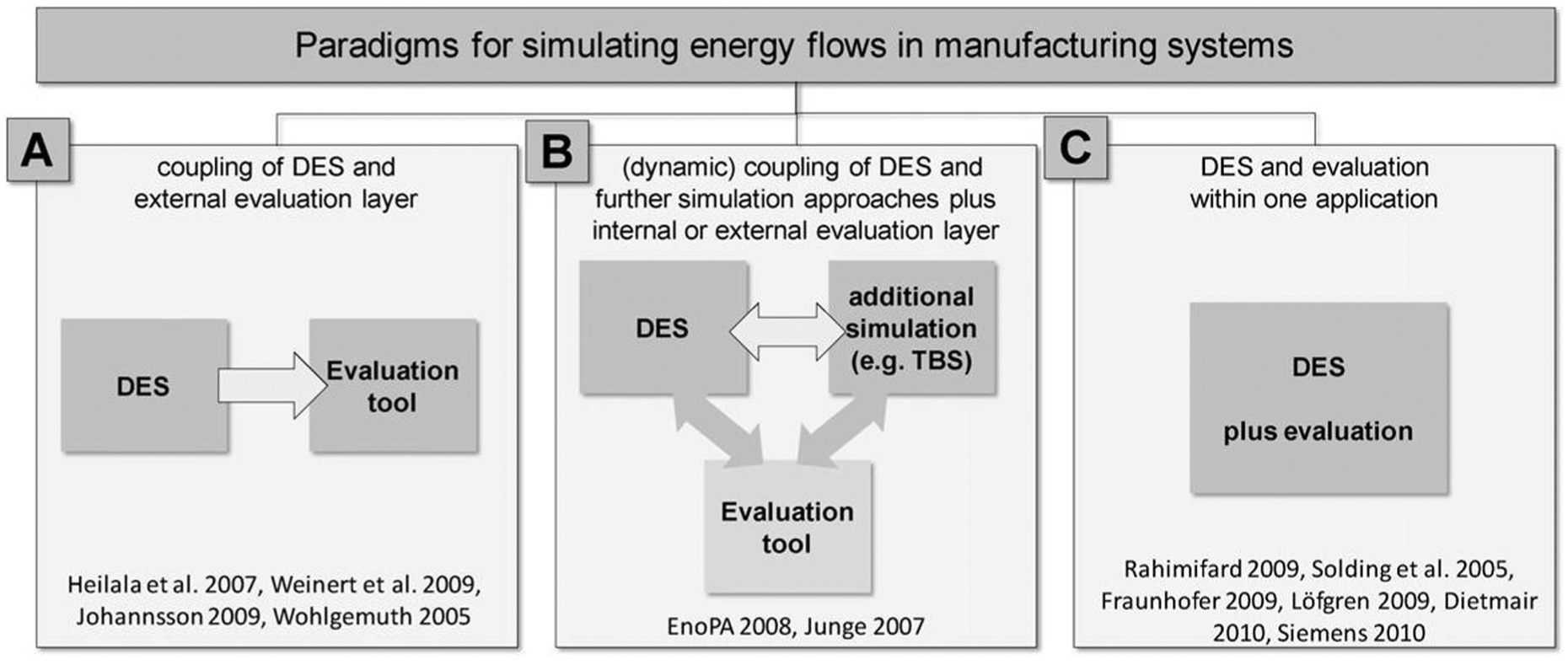
The three paradigms for coupling environmental assessment with DES. 12
In Paradigm A,13–16 the DES module is used to simulate production systems and typical variables such as the state of the machine or the manufacturing duration. The outputs would be treated in an external evaluation tool where data are converted into environmental aspects, mainly the energy consumption. For instance, a simulation-based sustainable manufacturing system is proposed within the context of the SIMTER project 14 to achieve from the DES outputs a multi-purpose evaluation with integrated environmental, ergonomic, and technical aspects. Paradigm B17,18 groups approaches structured with a dynamic coupling of the DES with an assessment tool. This allows a more detailed analysis of environmental characteristics in considering existing interdependencies between different sub-systems or processes. For instance, the EnoPA Project 18 proposes a dynamic coupling of different DES simulation tools (production, technical building services, and building shell) with environmental tool in order to assess the energy efficiency of the production system. In Paradigm C,19–24 the environmental concerns are implemented within a single DES application. For instance, Dietmair and Verl 23 have proposed a Petri network-based simulation with a strong link to machine tool controls for estimating the electrical power demand of the machine tool.
The greater part of the production processes in a manufacturing company deals with the machining system. The orientation toward a virtual machining simulation can therefore be an effective tool for the success of sustainable manufacturing through the simulation of numerical control (NC) code. It allows predicting the effect of the implementation of a new machining facility, without interrupting production on the machine tools (CNC). Machining simulation has been proven as an effective tool to reduce costs, to improve quality, and to accelerate the time-to-market access of products. Virtual machining models simulate the kinematics, dynamics, or other behaviors of the system. A virtual machining model allows modeling and analyzing the operation on a machine tool, the execution of the NC program, and the material removal process. Analysis of data collected during the machining cycle is crucial to optimize the cycle time of a program, the tool lifetime, and the geometric quality of the workpiece. Using a virtual machine model, all experiments can be performed in a safe environment. 25
By analogy to the simulation of machining parameters, the CAD/CAM systems and the virtual machining seem the right application to integrate the environmental impact assessment of the machining operations. In such a context, it would be interesting to identify whether the CAD/CAM/CNC systems can include new features in the assessment of environmental impacts. Many research works were therefore conducted with the aim of promoting the integration of environmental parameters within the machining simulation. To address this issue, many researchers such as Thiriez and Gutowski, 26 Neto et al., 27 and Dietmair and Verl 28 have proposed approaches aiming at the optimization of environmental factors such as the duration of a cutting operation, the quantity of chips removed, the use of cutting fluids, and the energy consumption.
Later, for measuring the energy impact of using an NC machine, Kong et al. 4 have developed a model based on the planning of cutting path via the NC code to estimate the energy consumption and greenhouse gases emissions resulting from the machining process behavior. NC code controls the motion of the CNC and the cutting parameters, including the list of cutting tools, the specification of the machine, and the geographic information on the power grid mix (electric energy). The entries are then processed to estimate the time required for running the NC code and greenhouse gases emissions resulting from the operation on the machine tool during the execution of NC code. The outputs of this model characterize the performance versus the emission of greenhouse gases from the considered operation (Figure 2).
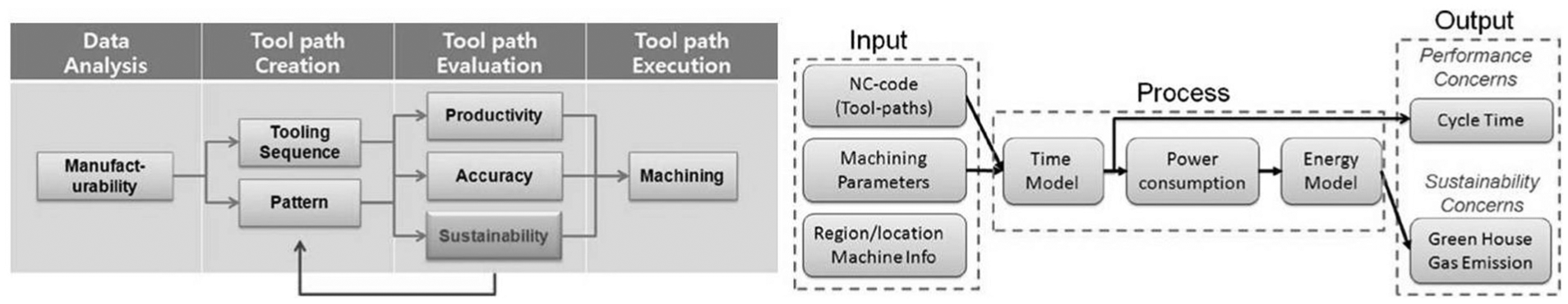
Simulation of tool path planning which incorporates the sustainability concern. 4
Recently, Zhao et al. 29 have used the information models of product and manufacturing process, including the STEP-NC standard. According to the authors, STEP-NC is the most appropriate structure and must be enriched with data on the environmental aspects of products and processes, as shown in Figure 3. With the proposed model, they aim at integrating information related to LCA (life cycle assessment)30,31 into the parameters of the product design and process planning. According to the interactivity of the CAD/CAM/CNC systems thanks to STEP-NC, the environmental knowledge and data accumulated during the manufacturing of the products or other life cycle stages (for instance end of life) can be returned to the design stage in terms of experience feedback to improve the environmental performance of new products.
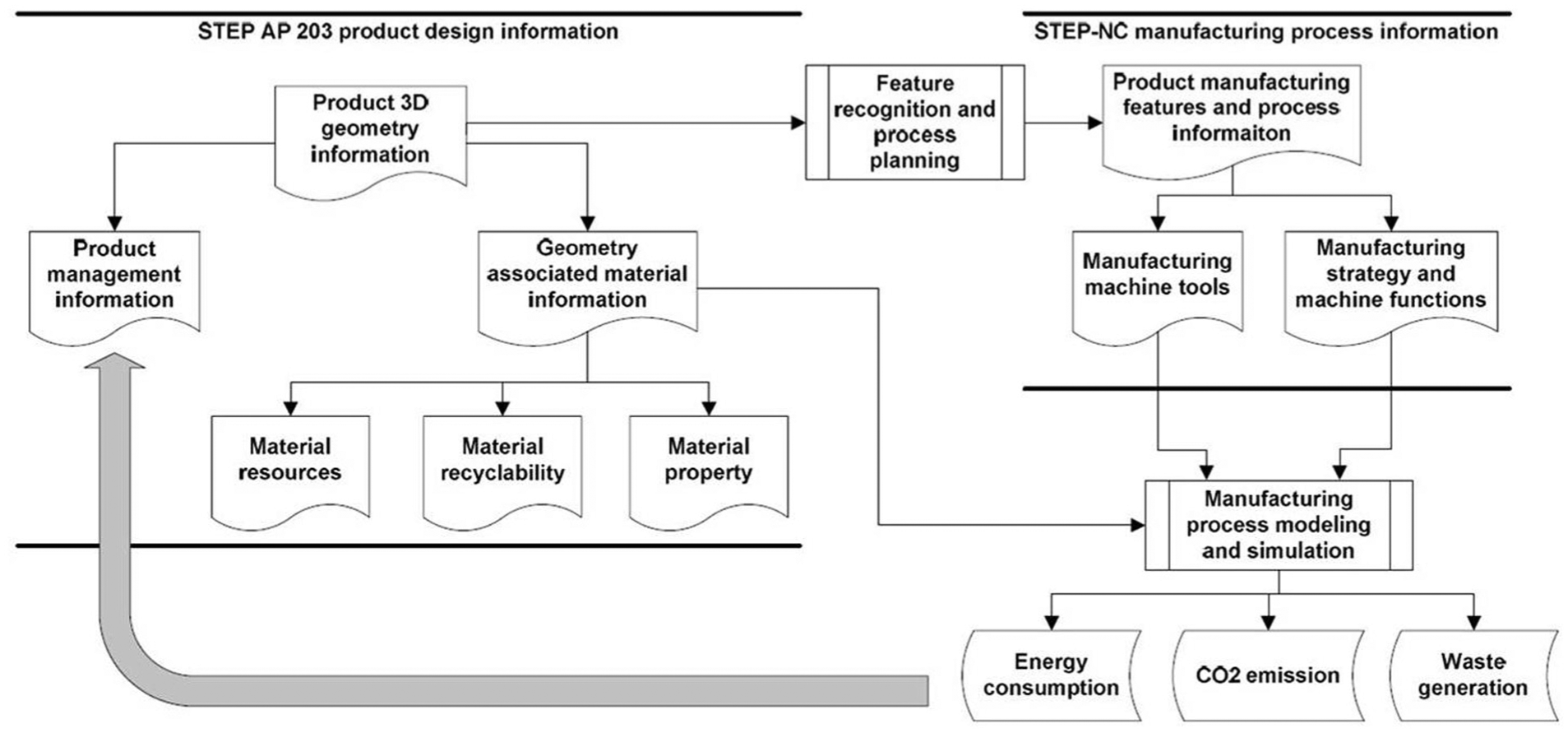
STEP and STEP-NC information models for integrating environmental aspects. 29
In terms of integration, the methods presented above can be grouped into two main categories. The first category includes approaches by coupling environmental tools with the software for simulation of the production system. The second one focuses on approaches by integrating environmental aspects through the digital manufacturing chain. Approaches in the first category encompass the entire production system and seem easy to achieve regarding the market availability of the DES-based software. However, the question arises on the appropriation of the environmental tools embedded in DES by the CAD/CAM engineers. Moreover, it is questionable whether the management of the simulation of the entire production system does not devote extensive material resources due to the extent of the scope to be taken into account. Indeed, the production system in its holistic vision 12 includes not only flows contributing to environmental impacts and costs of the production but also flows interacting with the infrastructure, which provide the power supply, computers and peripherals, and all other conditions necessary for the production. On the other hand, the assessment of environmental impacts through the NC simulation seems more accessible by the CAD/CAM engineers. However, this approach is focused solely on the machining system. Then, the risk of pollution transfer must be monitored.
The above research survey underscores the importance of indicators informing energy consumption. In terms of emissions, CO2 as a main greenhouse gas is often taken into account. Solid wastes are obviously reported by counting the flow of materials removed. The prudent use of non renewable resources is still one key element of sustainability. 32 Effective measures then tend to focus on the waste minimization and the reintegration of production solid wastes. These two aspects become essential since talking about the “sustainability” of machining processes.
In the design of a machining system, taking into account criteria such as system productivity, capacity, and other key performance indicators in the production system is a routine for the CAD/CAM engineers. However, taking into account potential environmental impacts (for instance, abiotic depletion and global warming) still remains a challenge although they can be mitigated by the approaches discussed above. The main problems are (1) difficulties in terms of time and effort needed for obtaining relevant data to perform a right environmental assessment and (2) difficulty to ensure the representativeness of the model to the CAD/CAM engineers in spite of the intangibility of environmental assessment through certain machining parameters (for instance, the variation of the global warming potential (GWP) impact when the depth of cut varies). These two barriers hinder to set up a relevant approach for reflecting the progression/regression induced by a machining system in terms of environmental impacts. The question needed to be clarified is, “How to develop and integrate a representative and an appropriable environmental assessment within the CAD/CAM/CNC system?”
CAD/CAM/CNC systems including environmental assessment
STEP-NC standard for continuous CAD/CAM/CNC systems
Digital technology has been set up in manufacturing companies for supporting the manufacturing system in reducing costs and time for the product development as well as for addressing the issues in increasing the product quality while for yielding more timely response to the market. 33 To manage the numerically controlled machines (CNC) integrated in the CAD/CAM/CNC system, tool paths are executed by programming the cutting tool motion. To achieve the best tool path planning, CAM systems can be used to generate this NC machining program. As input for those CAM systems, the geometric model is extracted from the CAD systems and then processed by the CAM programmer. Once the tool path is generated, the post-processor translates the CAM systems output (computer language) into compliant code for the CNC machine. The digital technology supporting the integration of CAD/CAM/CNC systems is illustrated in Figure 4.
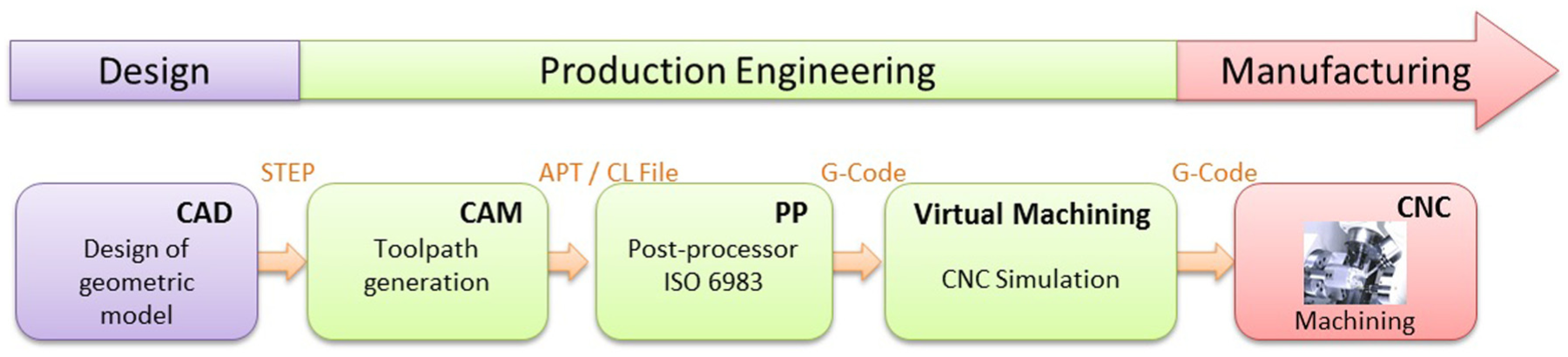
Integration of CAD/CAM/CNC systems supported by digital technology.
Interoperability between design and manufacturing support systems (CAD, CAM, post-processor, CNC machine, etc.) is led by specific files and standards.34,35 G-Code and M-Code led by the ISO 6983 standard 36 are the specific inputs for the CNC controllers. Each CNC controller has, however, its own proprietary data model to store and use machine tool–specific information. 37 A customization is then allowed depending on the controller vendors. To enable the data exchanges between the manufacturing machines and all other Computer-Aided X (CAX) systems which use these data, the implementation of a standard format seems a suitable solution. For first implementing the data exchange between CAD and computer-aided engineering (CAE), STandard for the Exchange of Product model data (STEP) has been developed. 38 STEP is an open standard that aims to promote the data exchange in a language which is understandable and shared by all systems. According to Rachuri et al., 39 the STEP standard provides a neutral, sustainable, and scalable data exchange format. In a similar way, for data exchange between CAM system and post-processor, two main standard formats have been developed: Automatically Programmed Tool (APT) and Cutter Location (CL) file. However, these standards do not allow information feedbacks from the post-processor to the CAM system.
To overcome this feedback issue, STEP-NC, a new standard format with enriched data has been developed in order to improve the systems interoperability40,41 by integrating “processing data.” The STEP-NC standard encompasses machining process, cutting tools description, and CAD features and requirements. This enriched standard format allows implementing in the same file all the information required for the whole development process from the preliminary design stages to the machining operations. 42
The STEP-NC standard is managed by two norms which address two different levels, application interpreted model (AIM) and application reference model (ARM):
ISO 10303 AP238 which concerns the AIM level. 43 The AP (application protocol) 238 entitled “Computer numerical controllers” mainly allows adding information for CNC machining. In this way, the STEP standard is enriched with the manufacturing features.
ISO 14649 deals with the ARM level. 6 This level is higher than the previous one as it also defines the machining strategy.
The STEP-NC standard structures a large number of information. Therefore, the same file can be used for all the CAX systems and then all the modifications are propagated from one to another. The use of STEP-NC also helps to enable the modifications between the manufacturing (shop floor) and the CAM programmer. Consequently, there exists no more consistency problem between CAM and CNC programs. All the modifications, thus the optimization made by the operators in the CNC machine, are translated in the STEP-NC file. This program can then be archived and re-used if necessary. Moreover, the use of STEP-NC is efficient because the post-processor can be removed. Indeed, as the machining intelligence is moved from CAM systems to CNC machines, the translation of the computer language into the machine language (post-processors and G-Code) becomes no more necessary. Tool paths are calculated based on the product model directly in the CNC, and data are formatted for execution by the machine within the CNC. Of course, it requires a customized command parser and command interpolator to process STEP-NC.
STEP-NC has been then developed by the ISO committee as a basis for the machining standard, the integration of different machining and control parameters. It is designed to replace traditional G-codes programming for allowing intelligent control of NC machines to increase industrial productivity. STEP-NC file provides for interfacing the CAD/CAM/CNC systems a detailed and structured data model (Figure 5). Machining data are mainly composed of various information such as the features (workpiece), the type of tools to use, the cutting operations to be executed (working steps), and the process plan (workplan). By providing this level of information to the machining system, STEP-NC allows a unified environment for information exchanges between the product design and the manufacturing process planning or control.
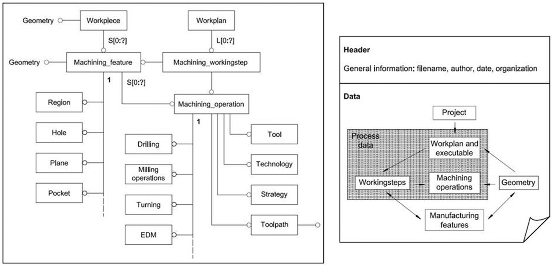
Overview of the ISO 14649 data model structure.
The structure of a STEP-NC file includes the following:
A header portion (Header) on general information on the program (author, date, etc.).
Information on geometry (Data): they contain the entities related to the machining strategy.
Writing the machining entities in the STEP-NC program is done through their decomposition into their simplest form, the form of pointers. To illustrate this decomposition, each 2.5 D machining entity is, for example, processed as an extrusion of a two-dimensional (2D) sketch. The sketch definition is made from polylines breakdown into basic form (segments, circles, etc.). The coordinates of the basic pointers of these forms are then listed line by line in the program. The numbers of the lines between parentheses are used to make the connection between pointers and the entities they describe.
Machining entities encompass the cutting data, which are the essential inputs for performing the environmental assessment within the CAD/CAM/CNC systems. The new proposal consists in enabling a dynamic environmental assessment of each cutting operation to implement in the machining system. In the next paragraphs, a focus is made on building a set of environmental performance indicators to power this proposition. Then, a case study protocol, based on input data from STEP-NC, is presented in section “Test case for eco-assessment of manufacturing operations” in order to illustrate the implementation method within the CAD/CAM/CNC systems.
Integration of a dynamic environmental assessment within the CAD/CAM/CNC systems based on STEP-NC
The term “dynamic assessment” qualifies the management of the environmental assessment by the manufacturing team from the process design to the manufacturing operation. The input data are progressively filled by the CAM programmer according to the data availability from STEP-NC. The assessment tool (eco-assessment) clarifies the environmental profile of the evaluated cutting technique. The results from the environmental assessment will be capitalized in the manufacturing process management (MPM) system. The environmental knowledge will be translated into guidelines for further enhancing tasks to reduce the environmental impacts of next machining operations to perform (see following section on implementation). The overall scheme for the new proposal integration within the CAD/CAM/CNC systems is illustrated in Figure 6.
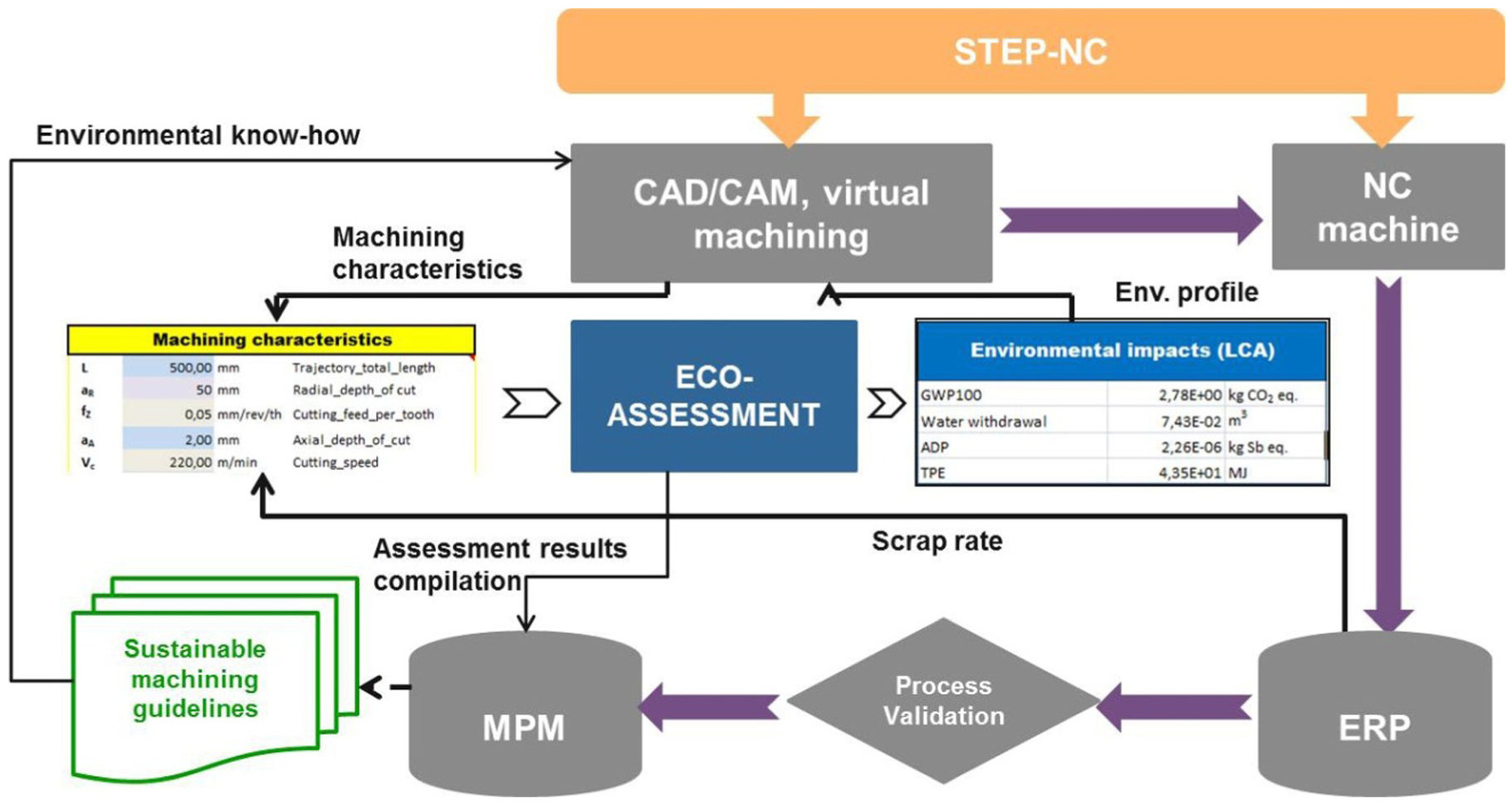
Framework for integration of environmental (eco-assessment) tool in the CAD/CAM/CNC systems based on STEP-NC.
Implementation
The machining data are first collected from STEP-NC to complete the environmental metrics. Additional data from the enterprise resource planning (ERP) system are needed for evaluating the scrap rate metric. The second step deals with the environmental impact assessment through the completed environmental metrics and thanks to the simplified LCA database. The environmental profile of the machining system is then provided to the production and manufacturing teams that generate ideas for improvement, if the environmental impacts are found critical. The undertaken improvement tasks consequently induce changes in the CAM outputs for the STEP-NC. Meanwhile, the results from the assessment of environmental performance are capitalized in the MPM system to consolidate an environmental knowledge base. Furthermore, guidelines for sustainable machining can be established based on the collected environmental knowledge for enhancing continuous improvement actions (Figure 7).
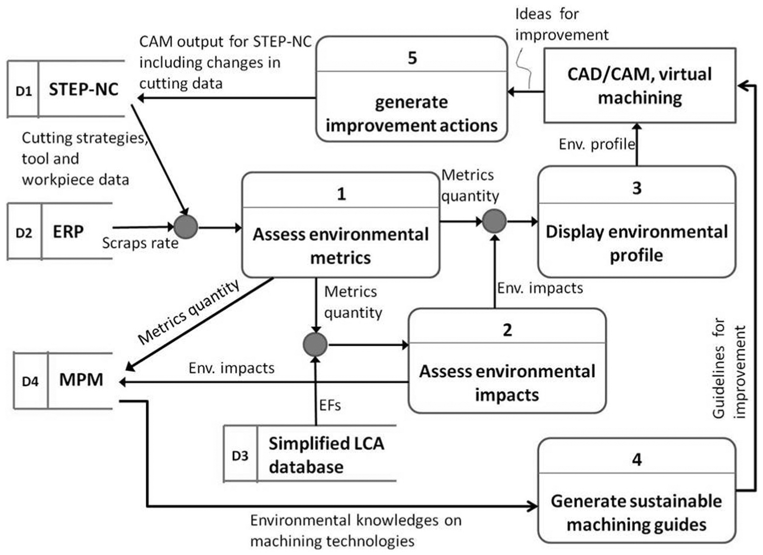
Data flow diagram of the implemented environmental assessment.
Moreover, this proposal is designed to be upgradeable by foreseeing two levels of actions. The first level consists of trial-and-error tasks for assessment and improvement of the environmental profile of machining operation. It is the first implementation (introduction stage) of the environmental assessment within the CAD/CAM/CNC systems. The second level consists of a decision-making to select a more environment-friendly machining operation. This kind of tasks can only be achieved when a sufficient background from previous tasks is available in the MPM system. This level then corresponds to the routine implementation (maturity stage) of the environmental assessment.
Environmental key performance indicators
Defining key indicators to assess the environmental profile of a global production system is a comprehensive task. Various indicators are available to assess the environmental performance of products and manufacturing processes. Seiffert 44 has clearly distinguished “environmental aspects” with “environmental impacts” and has illustrated the correlation between them. For example, energy consumption (an environmental aspect) contributes to the depletion of natural resources (an environmental impact). In addition, Tam 45 has distinguished environmental indicators according to their industrial usefulness. The first category concerns the indicators used in environmental reports, such as GWP, total primary energy, and eutrophication. The second category includes the indicators used in the context of environmental strategies such as reduction in energy consumption. The third category encompasses functional indicators that cannot be measured per unit of product but rather by the function that this product meets such as the amount of electrical energy consumed per X hours for Y machining operation.
The first category of indicators addresses more global aspects and cannot report on specific requirements such as the legislation targets. These indicators are obtained by carrying out LCA. In the following sections, these indicators will be identified as “(environmental) impact indicators.” The second and third categories seem closer to the current industrial practice or, in any case, can report on the legislation targets that industries must achieve. In the following sections, these will be called “environmental (engineering) metrics.”
Referring to section “Research background,” the indicators used by existing approaches of sustainable manufacturing are more oriented toward the common use of environmental metrics (for instance, energy consumption or CO2 emissions). In this work, the environmental indicators selected to implement the proposal are composed of environmental metrics and impact indicators. The methods used for their calculation are summarized in Table 1.
Key environmental indicators for eco-assessment.
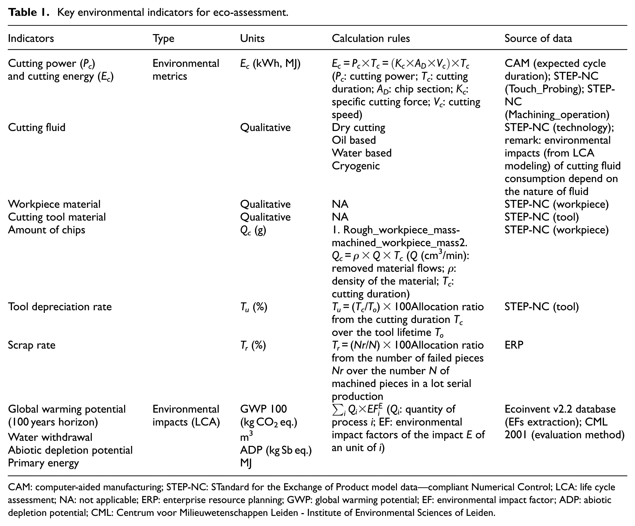
CAM: computer-aided manufacturing; STEP-NC: STandard for the Exchange of Product model data—compliant Numerical Control; LCA: life cycle assessment; NA: not applicable; ERP: enterprise resource planning; GWP: global warming potential; EF: environmental impact factor; ADP: abiotic depletion potential; CML: Centrum voor Milieuwetenschappen Leiden - Institute of Environmental Sciences of Leiden.
Sustainability assessment of a machining operation is based on a comprehensive evaluation of the inputs and outputs of the process. Machining process interacts with the environment through energy consumption and material and other consumable flows. LCA has emerged as the most objective tool available for evaluating the environmental impacts of a product or a process. Environmental assessment with LCA consists of serial comprehensive tasks from collecting technical data, through modeling the product/processes till translating input/output flows from the modeled processes into environmental impact indicators. Since it has been admitted that a direct integration of the full LCA in the product development process is not possible,46–50 simplifying its comprehensive feature for integration within the development of product/process becomes a relevant topic for research on ecodesign field. Many approaches have been developed to simplify the initial concept of full LCA, transforming these into tools applicable in design situations. 51 These approaches are referred to as streamlined, abridged, scoped, screened, approximated, or surrogated LCA and are generally qualified as less expensive methods for yielding more timely information. No consensus has been yet stated about the exact methods or procedures that could be used for simplifying LCA or about their appropriate uses. But certain basic features have been established by the Society of Environmental Toxicology and Chemistry (SETAC) 52 as a guide for helping LCA practitioners to consider the potential implications and effects of applying various scoping and streamlining decisions. These suggestions can be summarized into five criteria:
Reduce the amount of data to be collected (quantity);
Enhance the use of well-known and/or primary data (quality);
Reduce the amount of time;
Remove the workload in the life cycle modeling;
Facilitate result interpretation and enhance multicriteria decision-making.
In order to integrate LCA within the eco-assessment tool, a simplification of its comprehensive feature is operated by enhancing first the use of well-known data (for instance, cutting data from STEP-NC, CAM, MPM, or ERP). Moreover, for removing the workload in LCA modeling, environmental impact factors (EFs) are extracted from an LCA software package by modeling and evaluating a reference unit of a process i. Then, following an allocation rule, an impact E for the process i is linearly correlated to the corresponding environmental impact factor
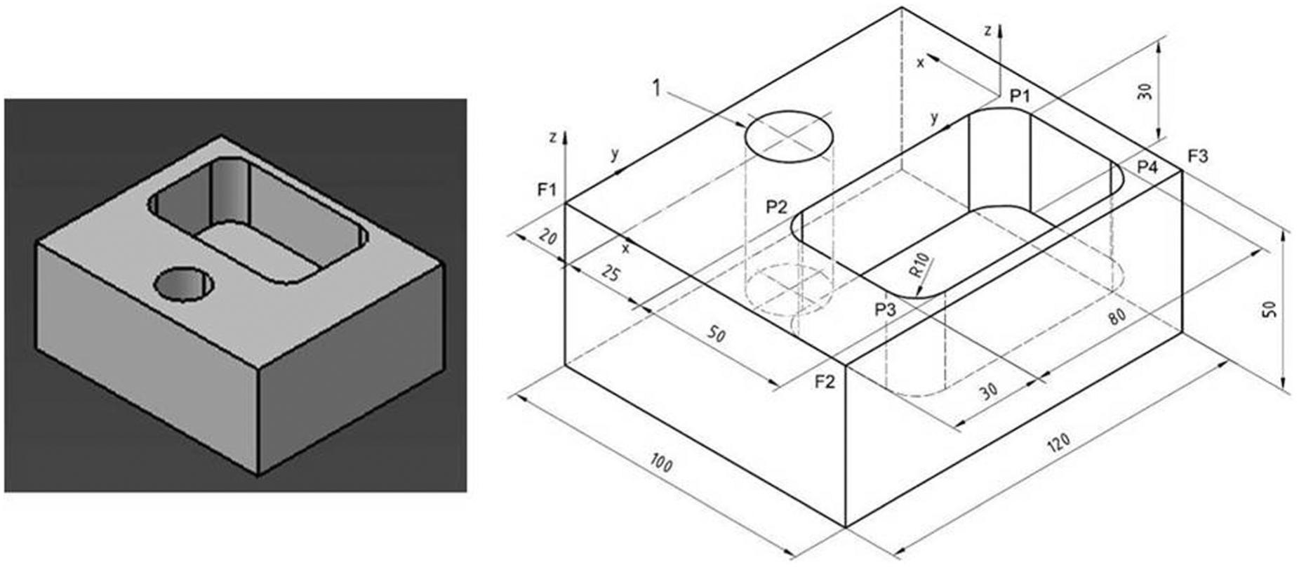
3D models of the ISO 14649 workpiece featuring its geometrical forms and dimensions.
The following section dealt with the test case definition for validating the above detailed proposition. In the same way, the architecture of the eco-assessment tool will be described meanwhile the tool usage will be illustrated.
Test case for eco-assessment of manufacturing operations
The test case chosen to illustrate this research work is the ISO 14649 workpiece. It is a prismatic form including two geometric features: a hole and a closed pocket (Figure 8), respectively, obtained by drilling and end milling processes.
To evaluate the proposed approach, the environmental assessment is applied to the end milling of the closed pocket. In the following, the chosen cutting strategy for the pocket milling will be simulated by the mean of the eco-assessment tool for reflecting the environmental profile of machining operation.
Test case definition
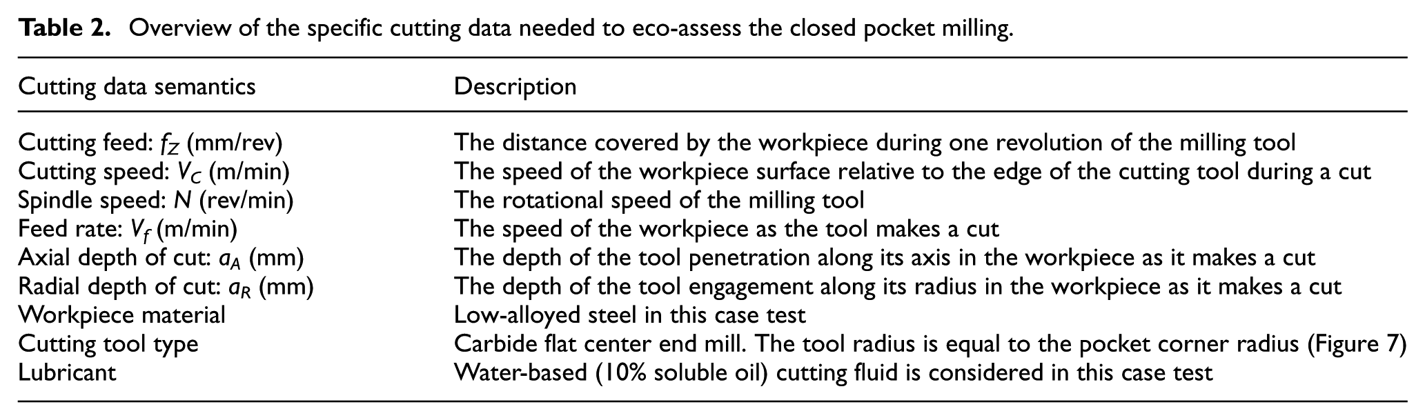
The specific cutting data needed from STEP-NC to run the environmental assessment of the pocket milling are summarized in Table 2.
Overview of the specific cutting data needed to eco-assess the closed pocket milling.
Establishing the cutting strategy is crucial to quantify the above cutting data. A feature is typically machined in several operations as the milling tool moves to the specified axial depth of cut for each operation step. If the radial depth of cut is less than the tool radius, the tool is only partially engaged and is making a peripheral cut. If the radial depth of cut is equal to the tool diameter, the cutting tool is fully engaged and is making a slot cut.
The definition of cutting strategy implies the generation of the tool path. Two general classes of tool paths are available: “trajectories” and “parameterized paths.” A trajectory is a calculated motion based on underlying elements, either a polyline or a spline. A parameterized path describes motions by the definition of the type and parameters of the motion (for instance, tangential approach). The exact motion itself has to be calculated by the CNC. A trajectory approach seems then suitable for simple tool path type, whereas the parameterized path approach fits more complex tool path type, thus for executing complex features.
For implementing the test case, two trajectories of tool path have been retained (Figure 9), based on the above arguments. A zigzag trajectory is attributed to the roughing passes (two slot cut steps of 10 mm axial depth of cut). The finishing pass (one peripheral cut step of 10 mm axial depth of cut) is executed in contour parallel trajectory to obtain better surface aspects.
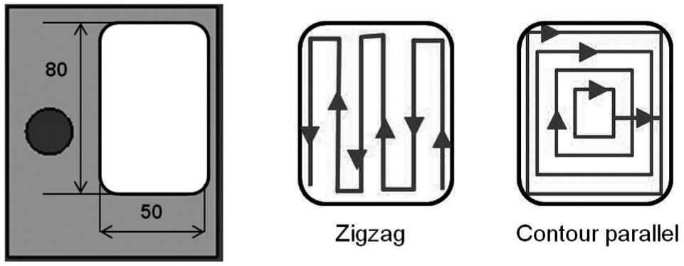
Proposed tool paths for milling the closed pocket.
Environmental performance assessment
Once the cutting strategy is defined, the cutting data are generated. Then, an environmental assessment can be progressively completed as described in the section on implementation. Figure 10 shows the implementation of the above cutting data as the inputs and the environmental profile as the outputs of the eco-assessment tool for use by the CAD/CAM systems.
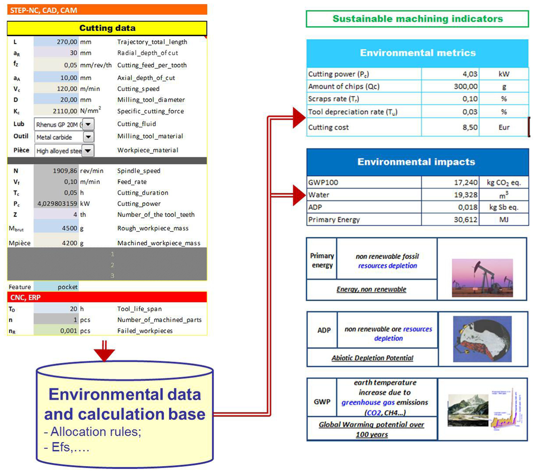
Eco-assessment tool mock-up interfaces.
In this case, one roughing pass executed with a zigzag tool path type and related cutting data are simulated. It means, for example, that the execution of this operation consumes 4 kW for 3 min (0.05 h), effective cutting duration. Moreover, its contribution to the greenhouse gas emission is about 17 kg CO2 eq., including the impacts contribution from the raw material extraction and from the machining process itself. Indeed, chips generated from cutting the rough part into the desired shape are parts of the input material flow of the process, before becoming a solid waste in the process output. Such elementary information from environmental assessment on a machining operation is quickly obtained with the eco-assessment tool. This ability to yield timely information allows the CAD/CAM engineers managing several environmental assessments on different machining operations.
Discussion
Research works on the sustainable manufacturing topic are growing fast and there exist numerous approaches proposed to manufacturing companies in order to enhance the benefits of the sustainability improvements. However, there is a lack of information in terms of practices, that is to say, appropriation and integration of these approaches within the product and process design team (such as CAD technicians or CAM programmers). Indeed, Despeisse et al. 53 have qualified these approaches as “high-level concepts” and thus hard to implement in industries, in terms of operational practices. Various modeling and analysis tools have been developed to mitigate this issue, but almost all of them are too less multicriteria (in terms of environmental impacts) to trace the environmental profile of a cutting strategy. Indeed, many approaches are successfully implemented.14,18,54–56 But they mainly report on the greenhouse gas emission and/or the energy consumption of the process during an operation. Moreover, another question is rising about the operational practices of sustainability assessment in the digital manufacturing chain integrating the STEP-NC standard.
In this study, a dynamic environmental assessment of the machining is presented. This assessment provides to the CAM programmers the opportunities to evaluate the environmental impacts of new machining operations during the manufacturing process engineering. Based on the STEP-NC standard, this approach is fully integrated to the digital manufacturing chain. The approach will be further completed with a definition of guidelines by extracting the data from the CNC and integrating the assessment of the machining operations based on these data. These assessments are stored in the MPM database. They can be thereafter used to help the CAM programmer to better choose the right machining parameters. Moreover, captured best practices from processes engineering knowledge can be shared beyond the manufacturing entities (CAM, CNC) and may be fed back into the product design (CAD) and even across the entire product life cycle management. 57
One limitation can be the low use of STEP-NC in industrial context because nowadays the implementation of STEP-NC is not yet fully achieved. Only few machines are able to read and execute STEP-NC code, and none of the main CAD/CAM vendors propose the STEP-NC output for their files. One solution is the use of algorithms that translate APT to STEP-NC during the production design phase and STEP-NC to G-Code before the manufacturing phase. This solution is employed to test the proposed approach on industrial context until a generalization of STEP-NC standard.
Sustainable manufacturing must be pursued from a global life cycle perspective that accounts for all activities across all life cycle stages. A second limitation is that transfers of impact from one stage to another have to be noticed if they occur. Indeed, a change on a machining operation may have environmental impacts on other life cycle stage.
Despite these limitations, and after interviewing industrial experts, it was concluded that most of the improvements done on machining operations do not affect other life cycle stages (as it is the same parts that are manufactured in the same factory). Thus, the transfers of impacts are unlikely to happen. Further investigation, particularly through industrial case studies, is advocated to evaluate this assertion and identify potential needed changes. STEP-NC is considered to be the next standard for the digital manufacturing. Hence, the proposed approach based on STEP-NC is an important step to integrate sustainable concerns in this new standard.
Conclusion and future work
Sustainable manufacturing is a promising approach to produce more sustainable products. In order to correctly implement it, companies have to integrate the environmental impact assessment of machining operations earlier into the process development, and not only at the end of the manufacturing process engineering. One of the main difficulties is to find the right data and to use them to calculate environmental impacts.
This article has presented a methodology developed to integrate the environmental assessment of machining operations during the manufacturing process engineering. This dynamic assessment is used to try new cutting strategies, tools, and machines to choose the best one without heavy impacts on cost and time to market. This methodology is based on STEP-NC. It extracts the right data from the processed CAM files and calculates the environmental impacts according to the extracted data. The use of cutting data directly extracted from STEP-NC as main inputs is expected to facilitate the access of non environmental expert such as the CAM programmers on the environmental assessment tasks.
Sustainable machining has great potential to offer more sustainable products and processes. The proposed approach can lead to rise up the creativity of the manufacturing team to create and choose new machining strategies. Although the future of this study is waiting for the generalization of STEP-NC, it is hoped that the research work reported in this article can help the manufacturing companies having a better understanding of the environmental issues affecting the manufacturing system.
Footnotes
Acknowledgements
The authors thank all consortium partners for their contribution during the development of ideas and concepts proposed in the article.
Declaration of conflicting interests
The author(s) declared no potential conflicts of interest with respect to the research, authorship, and/or publication of this article.
Funding
The author(s) disclosed receipt of the following financial support for the research, authorship, and/or publication of this article: This work developed during the industrial research project entitled ANGEL was supported by the French Government via BPI France under the grant number “F1210028Q.”