
Abstract
Metal sheets have the ability to be formed into nonstandard sizes and sections. Displacement-controlled computer numerical control press brakes are used for three-dimensional sheet metal forming. Although the subject of vendor neutral computer-aided technologies (computer-aided design, computer-aided process planning and computer-aided manufacturing) is widely researched for machined parts, research in the field of sheet metal parts is very sparse. Blank development from three-dimensional computer-aided design model depends on the bending tools geometry and metal sheet properties. Furthermore, generation and propagation of bending errors depend on individual bend sequences. Bend sequence planning is carried out to minimize bending errors, keeping in view the available tooling geometry and the sheet material properties’ variation. Research reported in this article attempts to develop a STEP-compliant, vendor neutral design and manufacturing framework for discrete sheet metal bend parts to provide a capability of bidirectional communication between design and manufacturing cycles. Proposed framework will facilitate the use of design information downstream at the manufacturing stage in the form of bending workplan, bending workingsteps and a feedback mechanism to the upstage product designer. In order to realize this vendor neutral framework, STEP (ISO 10303), AP203, AP207, and AP219 along with STEP-NC (ISO14649) have been used to provide a basis of vendor neutral data modeling.
Keywords
Introduction
Discrete sheet metal parts are manufactured in two steps: in the first step, two-dimensional (2D) flat blanks are cut from sheet metal stock and various features are produced over them by machining and stamping processes. In the second step, prepared flat blanks are formed on a computer numerical control (CNC) press brake to achieve the required three-dimensional (3D) part shapes. A variety of manufacturing equipments are used for both the manufacturing stages. Manufacturing process planning for discrete sheet metal parts requires the evaluation of an optimum sequence for both manufacturing stages depending on the nature of available manufacturing resources.
A variety of software tools are used to automate the activities of design, manufacturing and inspection of discrete sheet metal parts. CNC press brake process control units contain specialized unfolding software modules to unfold sheet metal computer-aided design (CAD) models to estimate shape and size of the starting 2D flat blanks. Computer-aided process planning (CAPP) software modules for discrete sheet metal parts are inherently different from discrete machined parts. Manufacturing process planning in the case of discrete sheet metal parts involves the evaluation of starting 2D flat blank geometry, blank machining strategy and 3D forming and gauging strategy.
Specialized offline computer-aided manufacturing (CAM) software modules are used to generate vendor-specific NC code for CNC machine tools to machine sheet metal blanks. Modern CNC press brake process control units utilize vendor-specific specialized unfolding and bend sequencing software modules to program punch displacements and back gauge finger-stop positions. Discrete sheet metal parts’ CAD models are based on the ideal scenario of circular straight modeling assumptions proposed by Ludwik 1 in 1905. These assumptions are almost impossible to meet in real-life manufacturing scenario of material and process variations. Discrete sheet metal parts’ design parameters are readjusted depending on the knowledge generated during bend sequence planning and test part forming. Design parameters readjustment and knowledge retrieval become cumbersome in the modern scenario of geographically dispersed design and manufacturing partners using heterogeneous software modules. Vendor-specific data formats of heterogeneous software modules make the process of feedback from downstream manufacturing activities to the upstream product designer almost impossible.
Significant research is reported in the literature in the area of vendor neutral design and manufacturing data modeling of machined parts to ease the process of knowledge retrieval. Research in the area of vendor neutral data modeling of discrete sheet metal parts is very sparse. With the aim of enabling vendor neutral data modeling across the entire sheet metal design and manufacturing process chain, this article outlines a design and manufacturing process planning framework for sheet metal bending based on STEP, STEP-NC and combined with additional information requirements.
Review of discrete sheet metal parts’ design and manufacturing processes
Computer-integrated manufacturing (CIM) in the modern scenario of geographically dispersed design and manufacturing partners using heterogeneous software tools make the process of data exchange cumbersome. Knowledge generated during final part manufacturing is seldom retrieved by the upstream product designer. Sheet metal blank machining process planning and execution is similar to conventional material removal machining processes. Sheet metal bending introduces global changes in blank geometry. Process planning related to sheet metal bending involves evaluation of an optimum bending sequence, tooling selection, individual punch displacements and back gauging strategy. Conventionally, bend sequence planning is mostly researched from the managerial perspective of minimizing total manufacturing time and cost. Bend sequencing effect on the overall part accuracy is least researched. Bending sequence and the bending process operating parameters are fine-tuned on the basis of test part bending results. Knowledge generated during manufacturing of test parts can be used to obtain potential time and capital savings if properly utilized in upcoming designs. Last era witnessed a big stride forward in the area of vendor neutral seamless product data flow in the overall CAx process chain. All these research activities are based on the infrastructure provided by a family of standards cumulatively known as STEP and STEP-NC.2,3 STEP-NC project (IMS-2003) of IMS (Intelligent_manufacturing_systems) provided a first true international platform to combine research partners from different regions: Switzerland, European Union, the United States and Korea. 4 Most of the research reported centers around developing prototype CAPP, CAM or computer-aided inspection (CAI) systems for turned and prismatic parts. Leading examples of these research activities include ISW Stuttgart, Germany prototype software platform, “STEPturn,”5,6 STEP tools inc USA software platform, “ST-Plan,” 7 Korean, National research laboratory software platform for shop floor programming and management,8,9 Loughborough University, Wolfson School of Mechanical and Manufacturing Engineering software platform, “AB-CAM,” 10 University of Auckland, Prototype STEP-compliant CAPP system for machined parts 11 and Ali et al., 12 STEP-enabled CAI framework for prismatic parts.
Chryssolouris et al. 13 described the history of digital manufacturing evolution and concluded that there is strong need of a vendor neutral product data representation standard to make possible a true seamless and bidirectional computer-aided engineering environment. Zhang et al. 14 proposed a meta-model for CNC part programming by utilizing STEP and STEP-NC. Andriankaja et al. 15 explained sustainable machining approach for CAD/CAM/CNC systems using STEP-NC. Vichare et al. 16 described a unified manufacturing resource model for machining using STEP-NC. Li et al. 17 explained recent advances in CNC machining research by utilizing STEP-NC. Xú et al. 18 demonstrated a feature recognition approach for reverse engineering of machined parts using STEP and STEP-NC. Hardwick et al. 19 proposed a roadmap for vendor neural, STEP-NC-enabled interoperable machining environment. Hu et al. 20 proposed architecture of a STEP-NC controller for closed-loop CNC machining.
Vendor neutral manufacturing data models developed for other nonconventional manufacturing processes include STEP-NC data model for wire electro discharge machining, 21 Stone machining, 22 rapid prototyping, 23 2D flat sheet metal blank machining 24 and 2D flat sheet metal blank feature recognition and reasoning system.25,26 Research reported in the area of vendor neutral manufacturing process planning for sheet metal parts is very sparse as compared to prismatic and turned machined parts. Majority of the research related to vendor neutral manufacturing process planning of discrete sheet metal parts is aimed toward blank machining. Sheet metal blank machining resembles in most respects with material removal machining processes and therefore vendor neutral blank machining research can be thought as an extension of material removal machining processes. 27
Literature review indicates that research in the area of vendor neutral bending process planning and programming for displacement-controlled CNC press brakes is very sparse and partial. This article investigates the area of discrete sheet metal parts’ design and manufacturing. An IT framework is developed based on contemporary standards STEP (ISO 10303 AP203, 224, 207), ISO_14649 and additional nonstandard manufacturing information. Proposed framework utilizes product information, manufacturing procedure information and manufacturing resources used. Scope of this research is to develop a STEP- and STEP-NC-enabled design and manufacturing process planning framework for CNC press brakes to support knowledge retrieval.
STEP-enabled manufacturing process planning for discrete sheet metal parts
STEP-NC provides an opportunity of feature-based manufacturing process planning and also facilitates the direct utilization of CAD data as input into the NC process chain. STEP-NC standard provides a vendor neutral bidirectional data model between design and manufacturing cycles. Departure of this vendor neutral bidirectional philosophy from conventional vendor-specific unidirectional data philosophy is shown in Figure 1. Contemporary standards STEP and STEP-NC provide the basis of design and manufacturing process chain closure. Based on these standards, a framework is developed for design and manufacturing process planning of discrete sheet metal parts bending. Significant feature of the proposed framework is the direct utilization of high-level design information in the manufacturing cycle in the form of a workplan, workingsteps and a mechanism of knowledge retrieval from manufacturing to the upstream design process. This framework is achieved by utilizing STEP (ISO 10303 Parts 203, 224, 207, 219) and STEP-NC (ISO_14649 Part 10,16) for product and manufacturing data models.
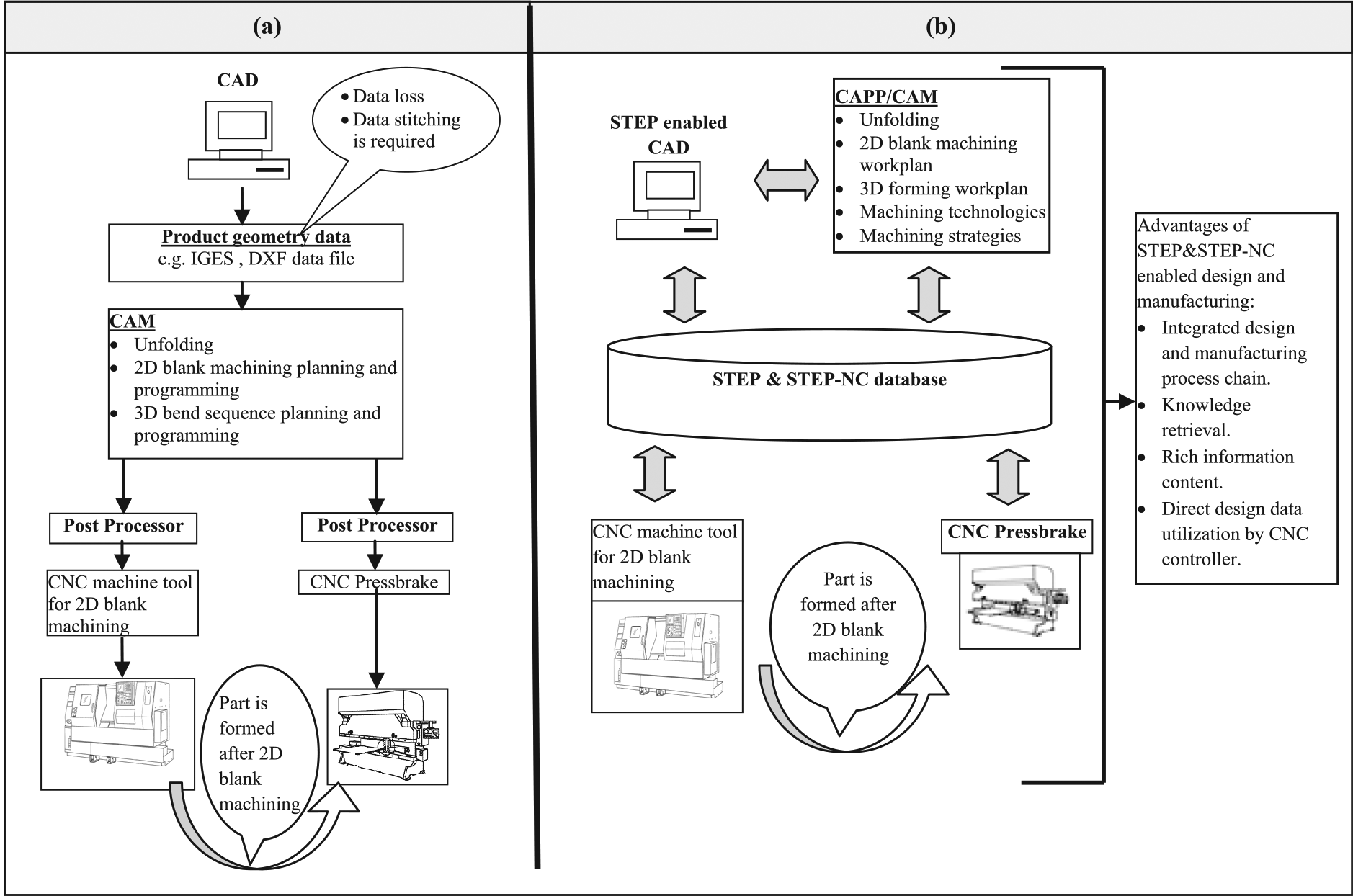
Comparison of conventional and STEP-enabled design and manufacturing process chain for sheet metal parts: (a) conventional process chain and (b) STEP-NC process chain.
Process of vendor neutral discrete sheet metal parts’ design and manufacturing is composed of several steps:
Vendor neutral product definition of the part.
Identification of individual manufacturing features and the associated tolerance requirements.
Identification of manufacturing resources required to manufacture individual features.
Manufacturing process planning and programming for individual manufacturing features by utilizing product and manufacturing data models.
Execution of the manufacturing program.
Analysis of manufacturing results and feedback to product designer.
Three main aspects of discrete sheet metal parts’ design and manufacturing process planning covered in the proposed framework are (1) standardized product definition based on contemporary standards STEP and STEP-NC by encompassing shape definition and the associated tolerances; (2) standardized manufacturing planning by specifying overall strategy, manufacturing procedures, program execution and the required resources; (3) analysis of the manufacturing results and feedback to achieve integrated process control and for overall data utilization across CAx process chain. Proposed framework produces generalized manufacturing process plan by utilizing manufacturing data model and design data model. Figure 2 depicts an extract of the authors discrete sheet metal part information models based on STEP data structure. Output of the framework is a generalized manufacturing process plan to be executed on a CNC press brake. During the course of generalized manufacturing process planning, part information is extracted from the part model to identify geometry and tolerance detail for the creation of workplan and individual workingsteps. Manufacturing information model provides resource information as per required bending sequence. Analysis of the final bending results is used to feedback manufacturing knowledge acquired to the planning and programming phase.
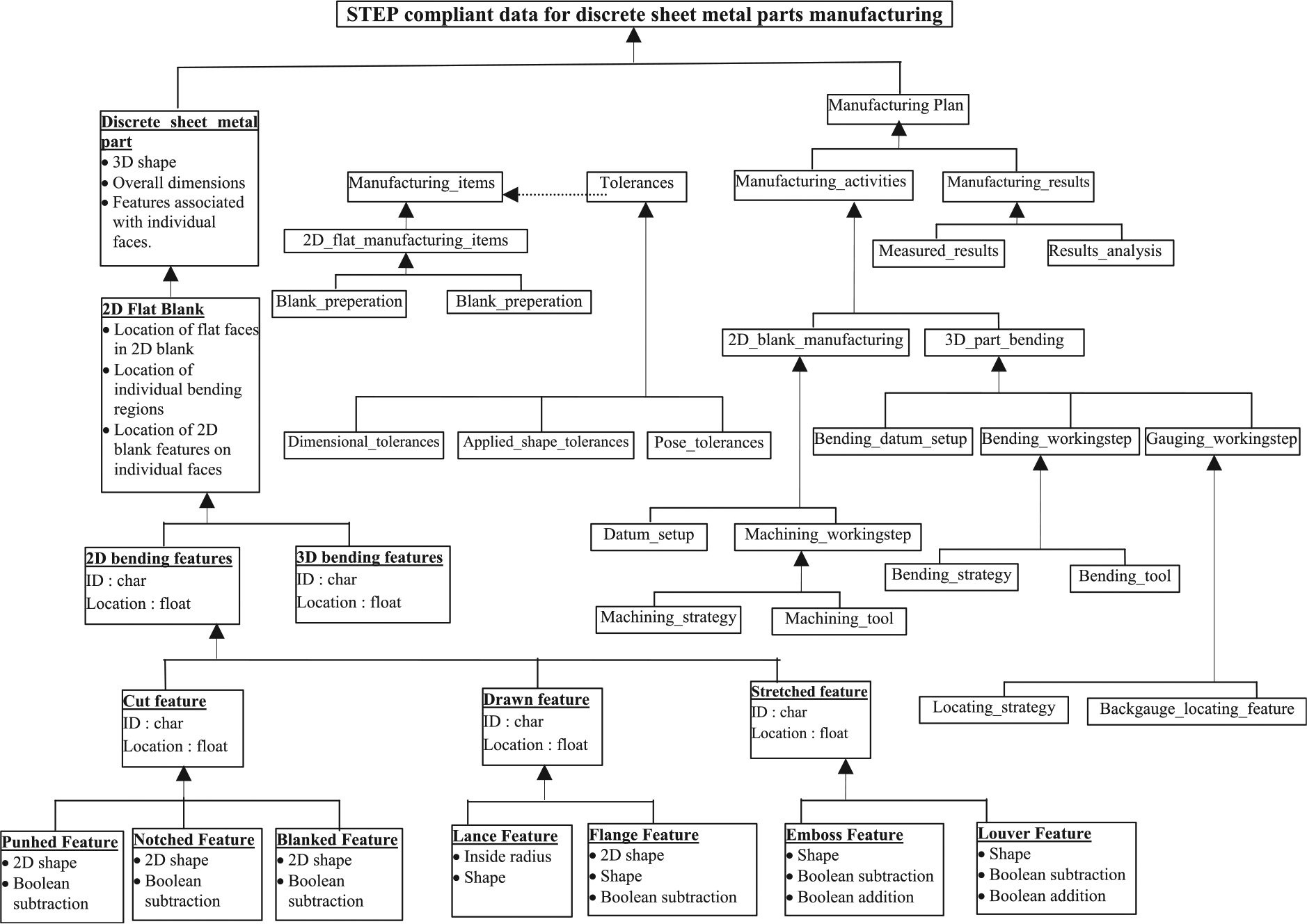
UML representation of STEP- and STEP-NC-enabled discrete sheet metal parts’ design and manufacturing.
Product information model for discrete sheet metal component manufacturing
Discrete sheet metal bent parts are composed of flat plates connected through a series of cylindrical section bends as shown in Figure 3. Overall part shape depends on the direction and included angle of the individual bends. Individual plates contain two profile defining faces; rest of the faces are thickness defining faces. To evaluate individual bend angles and bend directions, concept of running surface is utilized. Bend angles of individual bends in Figure 3(a) and (b) are the same but bend directions are different. Both of the plates have rectangular profile and four thickness defining faces. Individual plates are connected with bends through thickness defining faces.
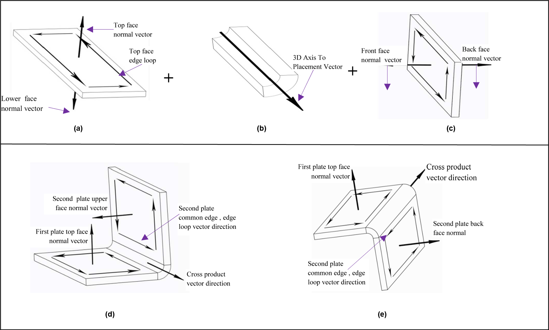
Cylindrical straight bends direction evaluation methodology: (a) first plate with respective face normal vectors and edge loops, (b) cylindrical bend with an axis to placement vector, (c) second plate with respective face normal vectors and edge loops, (d) concave bend in upward direction and (e) convex bend in downward direction.
In order to compute face normals of profile defining faces, edge loops are constructed in Counter Clockwise (CCW) direction. 25 Sheet metal CAD modeling starts with the development of a base plate. Rest of the plates are arranged sequentially with respect to parent base plate. 26 As shown in Figure 3, plate-2 can be connected with plate-1 in two opposite directions. Bend directions are evaluated by taking the cross product of the surface normal vectors of individual plate profile defining faces. For this purpose, both of the inner or both of the outer surface normal vectors of respective plates will be selected. This arbitrary selection is for the first plate connected to the base plate, for rest of the plates selection of individual face normals will be dictated by the running surface generated by the primary bends. For a particular bend if the direction of cross product of face normal vectors is the same as that of the direction of the common edge of the edge loop of the second plate, bend direction will be upside with a concave profile. Accordingly, if the directions are opposite, bend direction will be treated downward with a convex profile.
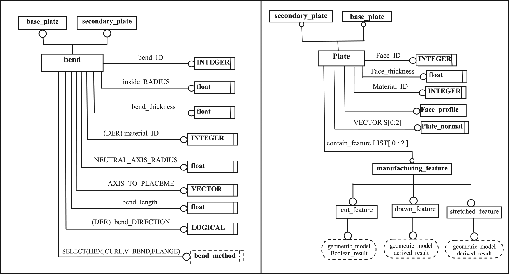
Product information model for discrete sheet metal parts supply necessary information regarding part shape, associated form and features to be manufactured. It also provides tolerance knowledge specified for overall part and individual features. Product information model actually encompasses both design and manufacturing phases. Knowledge required to define geometry, features and the associated tolerances is obtained from STEP standards. Discrete sheet metal part information model, depicted in Figure 4(a), serves the purpose of an information center by providing:
Component geometric information as defined in STEP (ISO 10303).
Individual locating and bending features.
Tolerances associated with overall part and individual features by utilizing STEP, STEP-NC and DMIS.
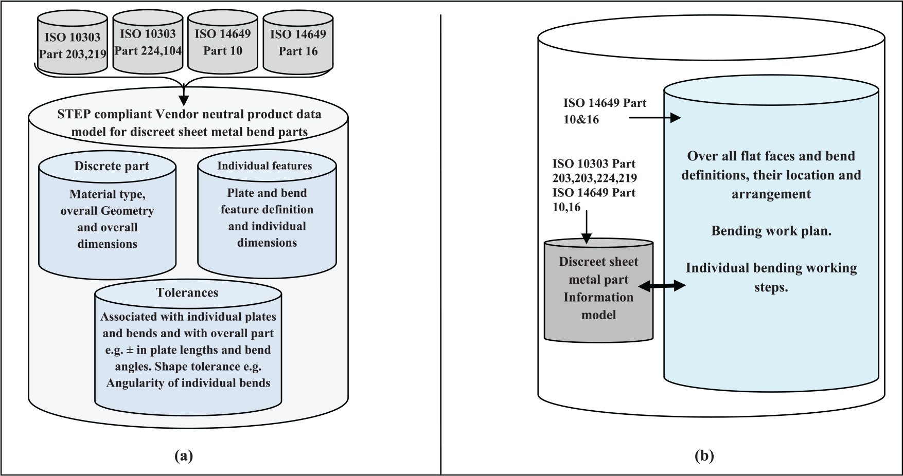
STEP-compliant vendor neutral design and manufacturing information models: (a) STEP-compliant product information model for vendor neutral manufacturing of discrete sheet metal bend parts and (b) STEP-compliant manufacturing information model for discrete sheet metal parts bending.
Some self-defined entities are also developed to bridge the information gap found for discrete sheet metal bend parts. EXPRESS-G diagram of the primary schema for this work is depicted in Figure 5. Discrete sheet metal parts are composed of individual plates connected through bends. One of the plates in the discrete sheet metal part will be a base plate to which all other plates will be connected sequentially. Starting plate in a sheet metal CAD model is known as base plate which is similar to a parent feature in solid CAD modeling of machined parts. 28 Base plate creation demands same care as is practiced during the creation of a base feature of a regular solid model. Rest of the plates are attributed as secondary plates. Secondary plates are referenced with respect to base plate.
EXPRESS entity definitions are as follows:
ENTITY plate
ABSTRACT SUPERTYPE OF(ONE OF (base_face,secondary_face));
Plate_ID : INTEGER;
Plate_thickness : float;
Material_ID : INTEGER;
Plate_profile_is : plate_profile;
Contain_feature : LIST[0:?]OF manufacturing_feature;
Plate_normal : VECTOR;
DERIVE
SELF\Plate.normal:VECTOR: = normal(plate_profile);
END ENTITY;
FUNCTION normal (PLANE_CROSS_SECTION):VECTOR;
(* compute normal of a plane*)
END_FUNCTION;
FUNCTION bend_DIRECTION(vec1,vec2:VECTOR);
(* compute cross product of two vectors “vec1” and “vec2”*)
LOCAL
Vec1: = plate1.normal;
Vec2: = plate2.normal;
END_LOCAL;
IF bend_DIRECTION == 1
RETURN(bend_DIRECTION: = UP);
ELSE
RETURN(bend_DIRECTION: = DOWN);
END_FUNCTION;
Individual plates of discrete sheet metal part are populated with manufacturing features.
ENTITY manufacturing_feature;
SUPERTYPE OF(ONE OF(cut_feature,drawn_featue,stretched_feature));
SUBTYPE OF(geometric_item);
END_ENTITY;
EXPRESS-G definition of cylindrical straight bends.
Manufacturing information model for discrete sheet metal component manufacturing
Manufacturing information model utilizes knowledge provided by product information model and at the same time encompasses data related to manufacturing process planning, resources to be used, execution of resource programming, results analysis and final feedback of manufacturing results. Manufacturing process planning and detailed part programming of the part to be manufactured depends on the specific attributes of the CNC resource used. Figure 6 depicts the flow diagram of the proposed framework and the mapping methodology of the final vendor neutral bending program to the CNC press brake. Output of the proposed framework is a generalized STEP-enabled feature-based manufacturing process plan for sheet metal bending. This generalized plan could be a direct input to an intelligent STEP-enabled process control unit of a CNC press brake or can be interpreted into a vendor-specific code for a conventional CNC press brake. Major feature of the proposed framework is the utilization of high-level design and manufacturing information in terms of a bending workplan, workingsteps and a bidirectional mechanism to feedback final bending results to the product designer. This purpose is achieved by utilizing STEP-NC parts 10 and 16 and STEP parts 238 and 219 for manufacturing data modeling. Sheet metal part to be formed on a CNC press brake is defined in terms of geometry and main dimensions, for example, individual plate dimensions and flat blank geometrical profile. In the next step, geometric and dimensional tolerances are added to the 3D part as well as 2D flat blank. The entity “work-piece,” that is, 2D flat blank, according to STEP-NC standard specifies material, surface condition and geometry in the form of a geometric model which is actually the state of some previous manufacturing operation, for example, sheet metal shearing. Proposed framework has the object-oriented data structure of STEP-NC standard for generating a bending process plan file. Bending and locating features are defined using 2 1/2 D manufacturing and transition features of ISO 14649-10. Geometric and dimensional tolerances are added to the main part as per ISO 14649 part 16 and ISO 10303 part 219. Geometric and dimensional tolerances are also added to each bending feature, for example, “±” tolerance added to the inside bend radius as a dimensional tolerance and parallelism tolerances added to the individual plates of the part. Based on the geometrical information provided by product information model, individual bending features and bending requirements are defined. Currently, insufficient information is available in STEP-NC standard for feature-based sheet metal manufacturing. Manufacturing information model generates a bending workplan which contains executables, that is, bending workingsteps for each bending feature present in the part. Bending workingstep includes bending operation, punch and die information and the gauging strategy. Each bending workingstep refers to a result statement where actual measured results are stored. Bending workplan for a discrete sheet metal part having “
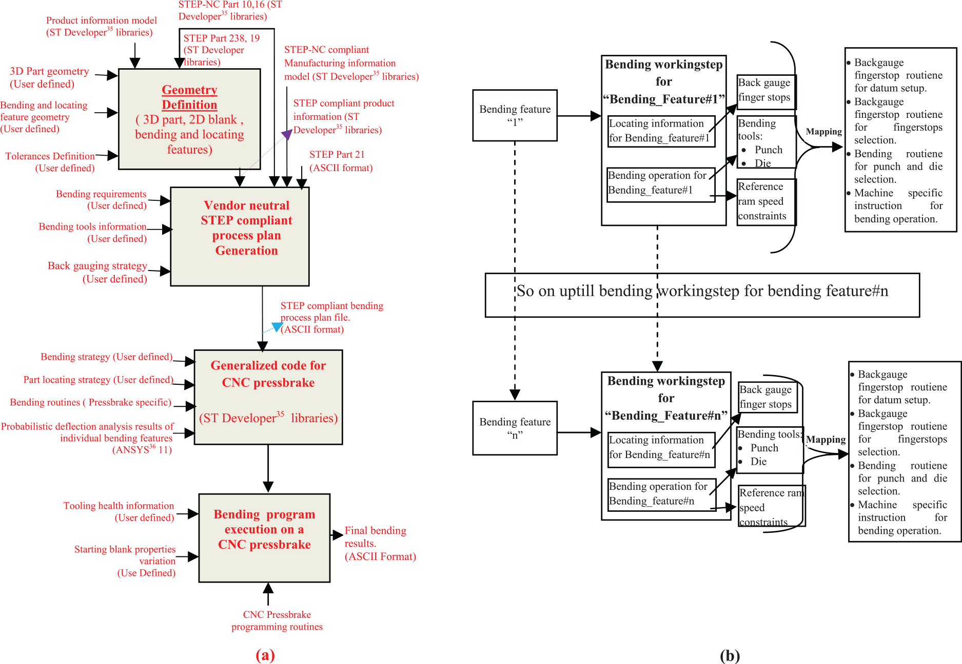
Working structure of the proposed vendor neutral design and manufacturing framework of discrete sheet metal bend parts: (a) flow diagram of the proposed framework and (b) vendor neutral bending workplan execution.
This file contains “Header” and “DATA” sections. Header section is composed of the project statement. Statements specifying information regarding part and feature geometry, bending items, associated tolerances, workplan, bending workingstep, bending and locating tools used and so on are part of the “Data section.”
These statements are updated with actual results obtained after bending part on a CNC press brake. This file can be interpreted for a specific CNC press brake. Bending results obtained from bent part inspection are fed back to update the bending file. STEP-NC bending file is composed of a number of bending workingsteps. Ideally, there is a single bending workingstep for each individual bending operation corresponding to individual bending features. Bending workingstep in the proposed STEP-NC file contains a set of bending items which can be combined into a single bending operation depending on the availability of tooling and press brake capability. Individual bending workingsteps can be directly mapped for CNC press brake specific bending instructions as shown in Figure 6(b).
ENTITY sheet_metal_bending
ABSTRACT SUPERTYPE OF (ONE OF(air_bending,bottom_bending,coin_bending,bottoming_with_springback));
SUBTYPE OF(sheet_metal_forming);
Punch_depth: length_measure;
Punch_speed: time_measure;
Its_forming_strategy: bending_strategy;
END ENTITY;
Where “punch depth” is the total distance punch has to travel to form the required angle. Initial punch displacements are estimated for individual bends by Ludwik 1 circular straight model assumptions. Actual punch displacements are estimated by Monte Carlo probabilistic deflection simulations and are fine-tuned by forming test parts. Punch displacement result statements are updated after final part bending and can be utilized for future parts design and manufacturing process planning. “Punch_speed” is the optional speed required for certain strain rate sensitive materials.
Bend sequence planning based on knowledge provided by product and manufacturing data models
Bending time and the dimensional accuracy depend on the bending sequence. In sheet metal bending, shape of the part is achieved by plastic deformation. Metal sheets are subjected to both thickness and material properties’ variation. DIN 1541 29 allows 15%–20% thickness variation for cold-rolled steel sheets and 20% yield strength variation is allowed by DIN 1623. 30 3D shape of the discrete sheet metal part is achieved by bending 2D flat blank, dimensions and shape of which are provided by product information model. 2D flat blank geometry is obtained by unfolding 3D sheet metal part model, which is based on ideal conditions of constant blank thickness and material property conditions. In actual practice, both of them vary within certain permissible level. Furthermore, for the case of air bending, developed bend lengths also depend on the geometry of bending tools. 31 Nominal punch and die sets are used by manufacturers for discrete sheet metal parts bending. Due to this reason, required 2D sheet metal blank differs in size from one manufacturing setup to other. Due to all these variations, required blank size differ than that provided by the product information model. Blank size and geometry are fine-tuned after bending test parts and by utilizing empirical equations for bending region developed length calculation. In V-bending, developed blank length and the inside radius depend on the die opening length. Accuracy of the final bent part depends on the accuracy in size of the starting 2D flat blank. In displacement-controlled CNC press brakes, angle bent on the part depends on the punch displacement. Punch displacements are calculated to overcome the spring back. Sheet metal bending is subjected to both material and process variations.
Inability of analytical models to tackle material and process variations arose the need of empirical equations to calculate blank sizes and ram displacements. Empirical equations utilize the most expected values of the material and process variations. In addition to all these blank size calculation errors, further error is caused during the blank shearing process. Bending errors generated during individual bending setups propagate during the execution of a bending sequence. 32
Propagation of bending errors depends on the particular bending sequence adopted. That bending sequence is feasible from accuracy point of view which yields lowest cumulative error. Generation and propagation of bending errors is mostly studied by taking constant deterministic process and material variations.
32
In real life, industrial practice material and process variations are probabilistic in nature. Therefore, expected error for each bending setup “

Monte Carlo probabilistic deflection simulations are utilized in this work to compute expected error associated with each bending setup. Potential material and process variations used in the deflection simulations are: 2D blank thickness variation, blank size variation caused by the blank shearing process, punch and die set alignment variation, blank positioning error variation caused by back gauge finger stops, blank material yield strength variation, punch displacement variation and the expected spring back variation. Analytical circular straight models compute spring back and developed blank lengths based on constant deterministic variables. Assumption of constant deterministic material and process variations cause an error of 0.3°–1° in spring back calculation and 5%–10% error in developed bend length calculation.
32
Figure 7(a) shows a 2D flat sheet metal blank located from left side. Part after bending is shown in Figure 7(b). As can be seen, actual position of the bent leg deviates from the nominal. Expected error in the position of the bent leg is the cumulative sum of the expected errors: locating error, blank length error, punch and die misalignment and the spring back. For an individual bending event, “

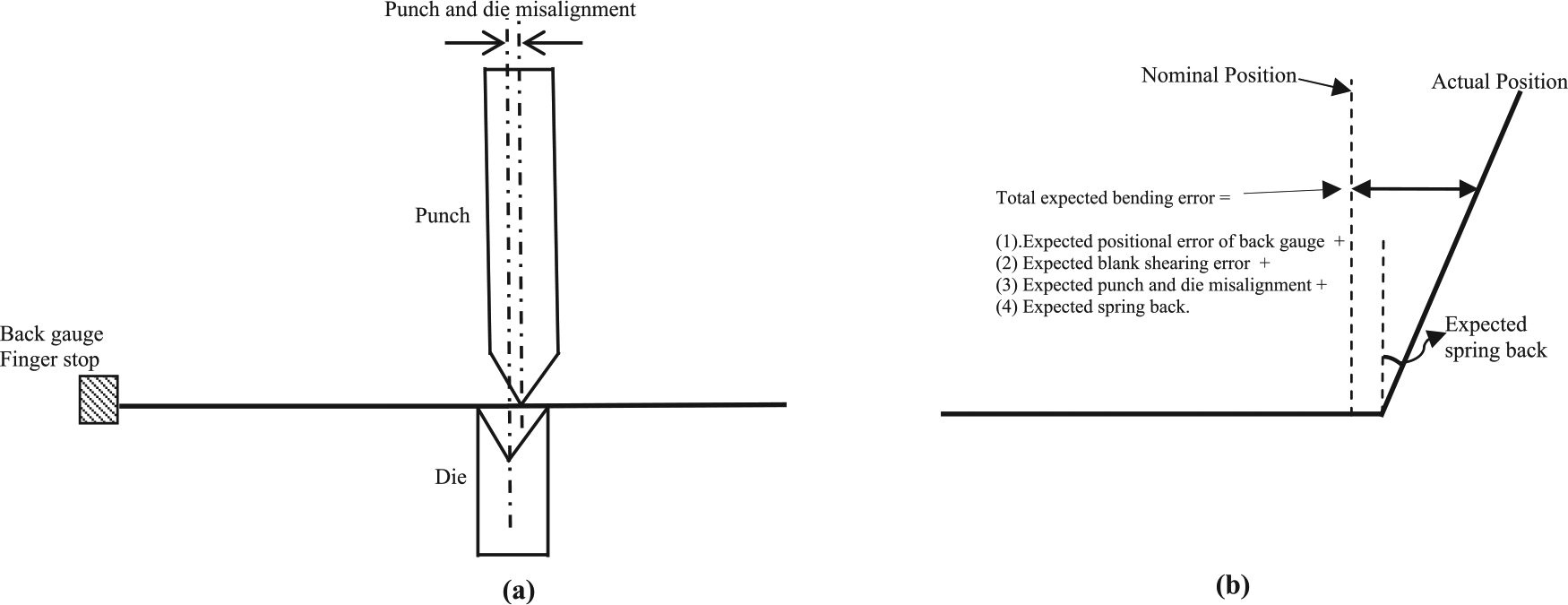
Expected bending error caused due to process and material variations: (a) initial bending setup and (b) part after bending with expected bending error.
Expected error of the sum of “
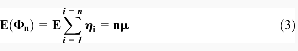
where “

From accuracy point of view that bending sequence will be optimum whose total bending error will be the lowest. Thus, for a bending sequence of “
Framework implementation for generation of manufacturing files for bending discrete sheet metal parts with straight line bends on CNC press brakes
STEP-compliant design and manufacturing framework for discrete sheet metal parts bending is utilized in this case study for an industrial bracket. Process of designing bracket in terms of flat sheet plates and individual bending objects is illustrated. Overall configuration of the bracket used in this work is the same used by Duflou et al. 32 in their work. Material properties data and accuracy specifications were absent in their work. Material selected for this case study is 2-mm mild steel sheets. Young’s modulus of the selected material is “210 GPa” and Poisson’s ratio “0.3.”Figure 8(a) shows required final 3D shape of the bracket. Critical bracket dimensions to be maintained during bending are leg lengths, distance between legs and base length. Figure 8(b) shows exploded view of the bracket, showing how this bracket is designed according to the proposed framework. Bracket is composed of 11 plates interconnected through a network of 10 individual bends. Inside radius of individual bends is taken equal to sheet thickness, that is, 2 mm. Developed blank of 3D bracket is shown in Figure 8(c). Developed blank dimensions are obtained by combining the lengths of flat sheet plates and the circumferential developed lengths of the individual bend features. In air bending included angle depends on the punch displacement. Developed length and the bend inside radius depend on the V-die opening width. Press brake tooling manufacturers devise empirical equations for the selection of tooling for various metal sheet grades. Punch and die tooling used in this case study for individual bends are from Cincinnati incorporated. 31 Tooling manufacturer recommends V-die opening width to be eight times blank thickness. For the case study part, it is 16 mm. Now a V-die will be selected whose opening width will be closest to 16 mm. Nearest available die in the available range has a die opening width of 19 mm and the accompanying punch has a radius of 1.6 mm. According to the empirical equations provided by manufacturer 31 for mild steel, inside bend radius will be.2.9 mm. Standard deviations selected for material and process variations are Ram reversal = 0.2 mm, punch and die centerline misalignment = 0.3 mm, back gauge positioning error = 0.2 mm, blank thickness variation = 0.1 mm, yield strength variation = 50 Pa and blank length shearing error = 0.5 mm. Monte Carlo probabilistic deflection simulations are run by utilizing ANSYS 35 programming capabilities. Figure 9 depicts relative frequency distributions of spring back and bends centerline deviation of bend-5. Expected cumulative bending errors evaluated from the respective frequency distributions and arranged in a From_To error matrix are shown in Table 1.
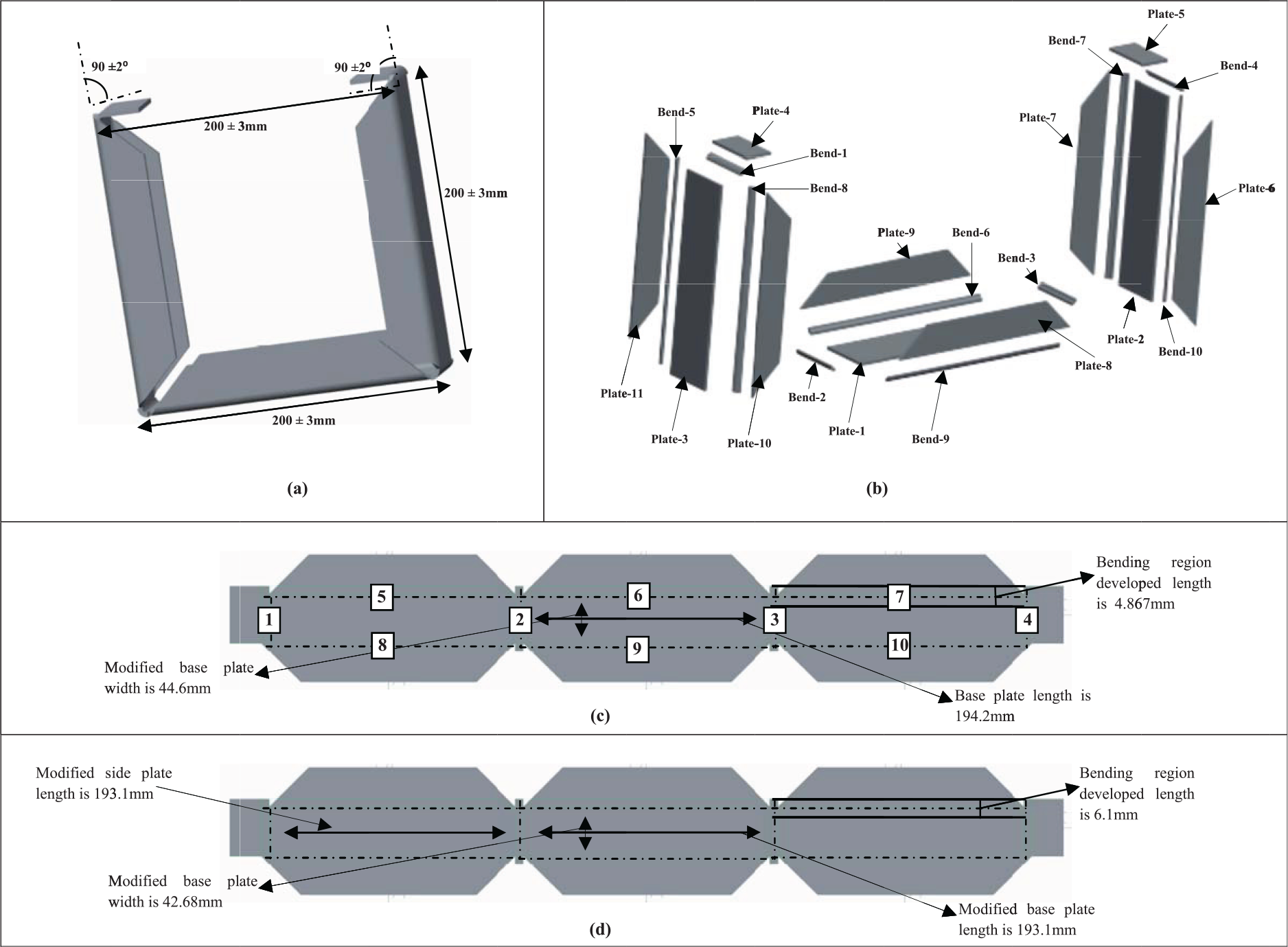
Case study part design and manufacturing scheme: (a) required part 3D geometry; (b) exploded view, representing individual bends and plates of 3D part; (c) flat blank required for the part; and (d) modified flat blank required for bending.
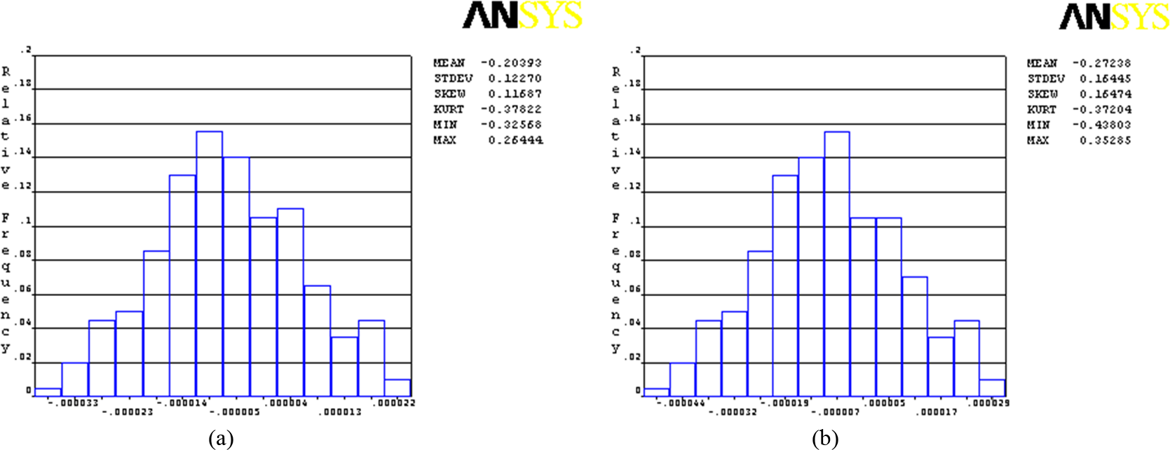
Monte Carlo probabilistic deflection simulation results for bend-5: (a) spring back frequency distribution for bend-1 and (b) bend centerline frequency distribution for bend-1.
From_To error matrix.
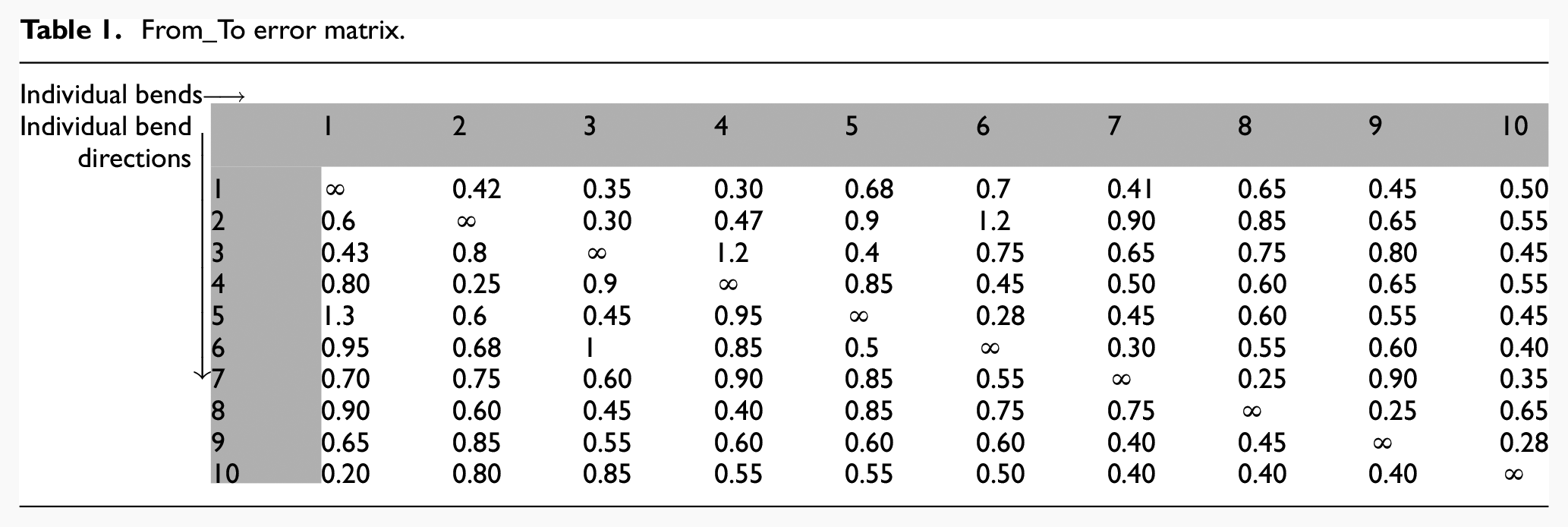
Branch and bound traveling sales man problem (TSP) algorithm proposed by Little et al. 34 in 1963 is used to solve this error matrix. Branch and bound tree generated by the algorithm is shown in Figure 10(a). Maximum and minimum possible bending errors associated with each bend pair is written over bend pairs in dotted rectangles. Optimum bend sequence evaluated from the tree is [5,6,7,8,9,10,1,4,2,3] with a total expected bending error of 2.41 mm.
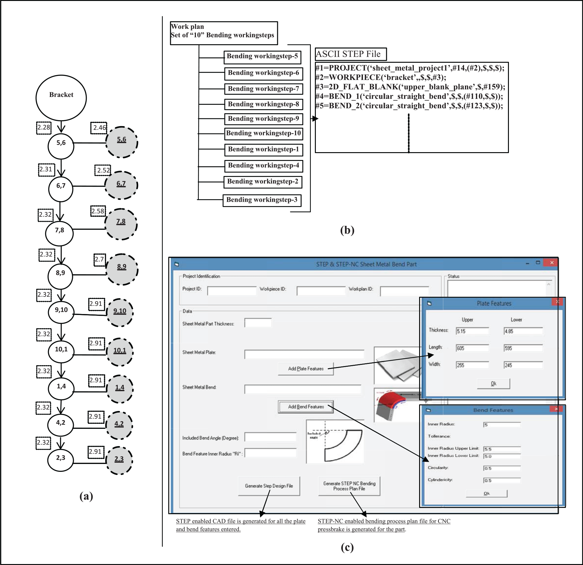
Generation of vendor neutral bending process plan file for case study part: (a) branch and bound error tree of test part, (b) STEP-NC-enabled bending process plan and (c) prototype IT platform for framework validation.
A prototype IT system is developed using ST-Developer Visual C++ programming libraries of STEP Tools, Inc. 36 to demonstrate the working of proposed framework. As shown in Figure 10(c), configuration of individual plate and bend features is entered in the prototype IT system. Software platform requires tolerances for both plate and bend features. Once the configuration of all the plate and bend features is entered, software generates two files, that is, a STEP-enabled CAD design file and a bending process plan file for CNC press brake process control unit. Both of these files are in character-based physical file formats.
Individual bending workingsteps are arranged to conform to the optimum bending sequence evaluated. Optimum arrangement of bending workingsteps is shown in Figure 10(b). Complete STEP-NC-enabled bending process plan file generated by the prototype IT platform for the part is given in Appendix 1. STEP-enabled bending process plan file contains a bending workplan which is composed of a total 10 bending workingsteps. Individual bending workingsteps refer to corresponding result statements which can be updated at the end of the bending setups.
This article proposes a vendor neutral design and manufacturing process planning framework for discrete sheet metal bend parts. Bend sequence planning depends on process and material variations which vary from one manufacturing setup to other. Potential design parameters are readjusted at the manufacturing level. Proposed vendor neutral framework will help knowledge retrieval and is most suitable for the modern low quantity high variety manufacturing scenario.
Conclusion
Knowledge retrieval from the manufacturing stage is the most critical requirement of modern low quantity high variety sheet metal manufacturing scenario. Starting sheet metal blank is subjected to both thickness and properties variation. Design parameters of discrete sheet metal parts are almost always readjusted at the manufacturing stage to achieve the critical dimensional parameters. Potential knowledge is lost by the vendor-specific design and manufacturing methodology used by the industry. Proposed framework is based on vendor neutral family of standards cumulatively known as STEP and STEP-NC. Missing information gaps are filled by self-defined entities. This novel framework helps to bridge the gap between design and manufacturing cycles for discrete sheet metal bend parts and facilitates knowledge retrieval from manufacturing stage to the upstream product designer.
Footnotes
Appendix 1
STEP-enabled bending process plan for the case study part
#1 = PROJECT(‘sheet_metal_project_casestudy’,#14,(#2),$,$,$);
#2 = WORKPIECE(‘bracket’,$,$,#3);
#3 = 2D_FLAT_BLANK(‘upper_blank_plane’,$,#159);
#4 = BEND_1(‘circular_straight_bend’,$,$,(#110,$,$));
#5 = BEND_2(‘circular_straight_bend’,$,$,(#123,$,$));
#6 = BEND_3(‘circular_straight_bend’,$,$,(#121,$,$));
#7 = BEND_4(‘circular_straight_bend’,$,$,(#119,$,$));
#8 = BEND_5(‘circular_straight_bend’,$,$,(#130,$,$));
#9 = BEND_6(‘circular_straight_bend’,$,$,(#128,$,$));
#10 = BEND_7(‘circular_straight_bend’,$,$,(#126,$,$));
#11 = BEND_8(‘circular_straight_bend’,$,$,(#113,$,$));
#12 = BEND_9(‘circular_straight_bend’,$,$,(#115,$,$));
#13 = BEND_10(‘circular_straight_bend’,$,$,(#117,$,$));
#14 = WORKPLAN(‘bending_workplan1’,(#15,#16,#17,#18,#19,#20,#21,#22,#23,#24),#35,$,$,$);
#15 = BENDING_WORKINGSTEP(‘BEND_1’,#4,#25,(#36,#37,#42,#44,#45));
#16 = BENDING_WORKINGSTEP(‘BEND_2’,#5,#26,(#36,#37,#42,#44,#45));
#17 = BENDING_WORKINGSTEP(‘BEND_3’,#6,#27,(#36,#37,#42,#44,#45));
#18 = BENDING_WORKINGSTEP(‘BEND_4’,#7,#28,(#36,#37,#42,#44,#45));
#19 = BENDING_WORKINGSTEP(‘BEND_5’,#8,#29,(#36,#37,#42,#44,#45));
#20 = BENDING_WORKINGSTEP(‘BEND_6’,#9,#30,(#36,#37,#42,#44,#45));
#21 = BENDING_WORKINGSTEP(‘BEND_7’,#10,#31,(#36,#37,#42,#44,#45));
#22 = BENDING_WORKINGSTEP(‘BEND_8’,#11,#32,(#36,#37,#42,#44,#45));
#23 = BENDING_WORKINGSTEP(‘BEND_9’,#12,#33,(#36,#37,#42,#44,#45));
#24 = BENDING_WORKINGSTEP(‘BEND_10’,#13,#34,(#36,#37,#42,#44,#45));
#25 = BENDING_OPERATION(form BEND_1,$,(#110,#50),#35);
#26 = BENDING_OPERATION(form BEND_2,$,(#111,#50),#35);
#27 = BENDING_OPERATION(form BEND_3,$,(#112,#50),#35);
#28 = BENDING_OPERATION(form BEND_4,$,(#113,#50),#35);
#29 = BENDING_OPERATION(form BEND_5,$,(#114,#50),#35);
#30 = BENDING_OPERATION(form BEND_6,$,(#115,#50),#35);
#31 = BENDING_OPERATION(form BEND_7,$,(#116,#50),#35);
#32 = BENDING_OPERATION(form BEND_8,$,(#117,#50),#35);
#33 = BENDING_OPERATION(form BEND_9,$,(#118,#50),#35);
#34 = BENDING_OPERATION(form BEND_10,$,(#119,#50),#35);
#35 = BENDING_STRATEGY(‘USER_DEFINED’,($, $, $, $, $, $, $, $, $, $), ($, $, $, $, $, $, $, $, $, $), $, $);
#36 = TOLERANCED_DIMENSION_ITEM(inside radius of bend,#38,$,(#40,#44));
#37 = TOLERANCED_DIMENSION_ITEM(bend angle,#39,$,(#41,#42));
#38 = TOLERANCED_LENGTH_MEASURE(2.0,#40);
#39 = TOLERANCED_ANGLE_MEASURE(90,#41);
#40 = PLUS_MINUS_VALUE(2.50,1.50);
#41 = PLUS_MINUS_VALUE(92,88);
#42 = TOLERANCED_POSE_ITEM(parallelism z,$,(#35,#43));
#43 = PARALLELISM_TOLERANCE(1.55,(#35,$));
#44 = TOLERANCED_SHAPE_ITEM(‘circularity of bend’,$,(#35,#46));
#45 = TOLERANCED_SHAPE_ITEM(‘cylindricity of bend’,$,(#35,#47));
#46 = CIRCULARITY(0.5,$);
#47 = CYLINDRICITY(0.5,$);
#48 = CARTESIAN_POINT(‘null’,(0.0,0.0,0.0));
#49 = REFERENCE_DATUM_SETUP(#48);
#50 = BENDING_TOOL(‘V die and punch set’,$,$,$,$,$,$,$);
#51 = DIRECTION(‘’,(0.7071,-0.7071,0));
#52 = DIRECTION(‘’,(1,1,0));
#53 = DIRECTION(‘’,(0,1,0));
#54 = DIRECTION(‘’,(-0.7071,0.7071,0));
#55 = DIRECTION(‘’,(-0.7071,-0.7071,0));
#56 = VECTOR(‘’,#51,56.35);
#57 = CARTESIAN_POINT(‘’,(0.0,0.0,0.0));
#58 = LINE(‘’,#57,#56);
#59 = VECTOR(‘’,#52,143.35);
#60 = LINE(‘’,#58,#59);
#61 = DIRECTION(‘’,(0.7071,0.7071,0));
#62 = VECTOR(‘’,#61,56.35);
#63 = LINE(‘’,#59,#62);
#64 = VECTOR(‘’,#51,56.35);
#65 = LINE(‘’,#63,#64);
#66 = VECTOR(‘’,#52,143.35.35);
#67 = LINE(‘’,#65,#66);
#68 = VECTOR(‘’,#61,56.35);
#69 = LINE(‘’,#67,#68);
#70 = VECTOR(‘’,#51,56.35);
#71 = LINE(‘’,#69,#70);
#72 = VECTOR(‘’,#52,145.35);
#73 = LINE(‘’,#71,#72);
#74 = VECTOR(‘’,#61,56.35);
#75 = LINE(‘’,#73,#74);
#76 = VECTOR(‘’,#52,48.65);
#77 = LINE(‘’,#75,#76);
#78 = VECTOR(‘’,#53,48.65);
#79 = LINE(‘’,#77,#78);
#80 = DIRECTION(‘’,(-1,0,0));
#81 = VECTOR(‘’,#80,48.65);
#82 = LINE(‘’,#79,#81);
#83 = VECTOR(‘’,#55,56.35);
#84 = LINE(‘’,#82,#83);
#85 = VECTOR(‘’,#80,143.35);
#86 = LINE(‘’,#84,#85);
#87 = VECTOR(‘’,#55,56.35);
#88 = LINE(‘’,#86,#87);
#89 = VECTOR(‘’,#54,56.35);
#90 = LINE(‘’,#88,#89);
#91 = DIRECTION(‘’,(-1,0,0));
#92 = VECTOR(‘’,#91,145.35);
#93 = LINE(‘’,#90,#93);
#94 = VECTOR(‘’,#55,56.35);
#95 = LINE(‘’,#93,#94);
#96 = VECTOR(‘’,#54,56.35);
#97 = LINE(‘’,#95,#96);
#98 = VECTOR(‘’,#80,143.35);
#99 = LINE(‘’,#97,#98);
#100 = VECTOR(‘’,#55,56.35);
#101 = LINE(‘’,#99,#100);
#102 = VECTOR(‘’,#80,48.65);
#103 = LINE(‘’,#101,#102);
#104 = DIRECTION(‘’,(0,-1,0));
#105 = VECTOR(‘’,#104,48.65);
#106 = LINE(‘’,#103,#104);
#107 = VECTOR(‘’,#52,48.65);
#108 = LINE(‘’,#106,#107);
#109 = VECTOR(0,1,0),48.65);
#110 = LINE(‘’,(0,0,0),#109);
#111 = ORIENTED_EDGE(‘’,$,#110);
#112 = VECTOR(‘’,#52,199.5);
#113 = LINE(‘’,#110,#112);
#114 = ORIENTED_EDGE(‘’,$,#110);
#115 = LINE(‘’,#113,#112);
#116 = ORIENTED_EDGE(‘’,$,#115);
#117 = LINE(‘’,#115,#112);
#118 = ORIENTED_EDGE(‘’,$,#117);
#119 = LINE(‘’,#117,#109);
#120 = ORIENTED_EDGE(‘’,$,#118);
#121 = LINE(‘’,#115,#109);
#122 = ORIENTED_EDGE(‘’,$,#121);
#123 = LINE(‘’,#113,#109);
#124 = ORIENTED_EDGE(‘’,$,#123);
#125 = VECTOR(‘’,#77,199.5);
#126 = LINE(‘’,#119,#125);
#127 = ORIENTED_EDGE(‘’,$,#126);
#128 = LINE(‘’,#126,#125);
#129 = ORIENTED_EDGE(‘’,$,#128);
#130 = LINE(‘’,#128,#125);
#131 = ORIENTED_EDGE(‘’,$,#130);
#132 = ORIENTED_EDGE(‘’,$,#58);
#133 = ORIENTED_EDGE(‘’,$,#60);
#134 = ORIENTED_EDGE(‘’,$,#63);
#135 = ORIENTED_EDGE(‘’,$,#65);
#136 = ORIENTED_EDGE(‘’,$,#67);
#137 = ORIENTED_EDGE(‘’,$,#69);
#138 = ORIENTED_EDGE(‘’,$,#71);
#139 = ORIENTED_EDGE(‘’,$,#73);
#140 = ORIENTED_EDGE(‘’,$,#75);
#141 = ORIENTED_EDGE(‘’,$,#77);
#142 = ORIENTED_EDGE(‘’,$,#80);
#143 = ORIENTED_EDGE(‘’,$,#82);
#144 = ORIENTED_EDGE(‘’,$,#84);
#145 = ORIENTED_EDGE(‘’,$,#86);
#146 = ORIENTED_EDGE(‘’,$,#88);
#147 = ORIENTED_EDGE(‘’,$,#90);
#148 = ORIENTED_EDGE(‘’,$,#93);
#149 = ORIENTED_EDGE(‘’,$,#95);
#150 = ORIENTED_EDGE(‘’,$,#97);
#151 = ORIENTED_EDGE(‘’,$,#99);
#152 = ORIENTED_EDGE(‘’,$,#101);
#153 = ORIENTED_EDGE(‘’,$,#103);
#154 = ORIENTED_EDGE(‘’,$,#106);
#155 = ORIENTED_EDGE(‘’,$,#108);
#156 = EDGE_LOOP(‘’,$,(#132, #133, #134, #135, #136, #137, #138, #139, #140, #141, #142, #143, #144, #145, #146, #147, #148, #149, #150, #151, #152, #153, #154, #155));
#157 = FACE_OUTER_BOUND(‘’,$,156);
#158 = AXIS2_PLACEMENT_3D(‘’,(0.0,0.0,0.0),#52,#53);
#159 = PLANE(‘’,#158);
#160 = ADVANCED_FACE(‘’,#158,#159);
#161 = BENDING_RESULT(#15,#35,$,$);
#162 = BENDING_RESULT(#16,#35,$,$);
#163 = BENDING_RESULT(#17,#35,$,$);
#164 = BENDING_RESULT(#18,#35,$,$);
#165 = BENDING_RESULT(#19,#35,$,$);
#166 = BENDING_RESULT(#20,#35,$,$);
#167 = BENDING_RESULT(#21,#35,$,$);
#168 = BENDING_RESULT(#22,#35,$,$);
#169 = BENDING_RESULT(#23,#35,$,$);
#170 = BENDING_RESULT(#24,#35,$,$);
#171 = GLOBAL_K-FACTOR_OF_SHEET_METAL_PART(0.5.)
#172 = (LENGTH_UNIT()NAMED_UNIT(*)SI_UNIT(MILLI,METRE));
#173 = (NAMED_UNIT(*)PLANE_ANGLE_UNIT()SI_UNIT($,RADIAN));
#174 = PLANE_ANGLE_MEASURE_WITH_UNIT(PLANE_ANGLE_MEASURE(17453E-2),#173);
#175 = CONVERSION_BASED_UNIT(‘DEGREE’,#174)NAMED_UNIT(*)PLANE_ANGLE_UNIT());
Declaration of Conflicting Interests
The author(s) declared no potential conflicts of interest with respect to the research, authorship and/or publication of this article.
Funding
The author(s) received no financial support for the research, authorship and/or publication of this article.