
Abstract
Induction Heating (IH) method is gaining traction in the field of Additive Manufacturing (AM) as it is a low cost, clean, safe, and precise energy source. Wire as a feedstock material is highly efficient as compared to the powder form in terms of material utilization and economic viability. Thus, the combination of IH and wire feedstock delivery to additive manufacture a part has been explored on an in-house developed novel AM setup. The processing of aluminum wire (Al-5356) in semi-solid form from the extruder, heated using IH method has been performed. The approach adopted in this paper is to perform an in situ infrared imaging to analyze the evolution of thermal field during the extruder heating and metal deposition process. An effective thermal cartography has been undertaken to acquire temperature history of filament, extruder, and deposition process. The temperature profile plot is utilized to understand the temperature distribution and average temperature in the heating, extrusion, and layering process during layer fabrication. The presented work facilitates a priori anticipation to utilize IH as a potential energy source for the metal AM systems.
Introduction
The genesis of the modern day additive manufacturing is regarded decades back with the development of rapid prototyping process. After two and half decades of its inception, the ASTM collectively designated the AM processes into seven categories of sheet lamination, Binder Jetting (BJ), Material Jetting (MJ), Powder Bed Fusion (PBF), Directed Energy Deposition (DED), vat photopolymerization, and material extrusion.1,2 Among them the well-known metal deposition processes of AM are DED and PBF.3–6 However the limitations associated with these AM methods are low deposition rates and high equipment cost. 7 An aspiring method to process metal is the material extrusion, which is commonly known to handle materials like polymers. 8 The Fused Filament Fabrication (FFF) technology under material extrusion category have a major chunk of utilization in modern day manufacturing among the AM technologies. The barrier that came in the way of material extrusion process to become a key player for Industry 4.0 realization is its limitation to handle metals efficiently.
Material extrusion category of AM (specifically FFF) involves the feedstock material to be fed in filament form through a heated extruder on a substrate in order to complete a layer and thereby a part.9–11 Implementation of wire filament as a feedstock is advantageous due to higher deposition rate, high material utilization, ease in handling, and repeatability.12–14 IH utilization to deposit metal is attempted by researchers.4,15–17 Induction heating is a clean, low cost, safe, and precise energy source and it is gaining traction in the field of AM.16,18,19 The manufacturing industries are prompting adoption of sustainable and efficient utilization of resources. 20 IH can be regarded useful in this respect. A fused coating technique using IH to melt Al alloy in a crucible and eject over a substrate was performed in research by Du and Wei. 21 A similar nature of work was performed by Vega et al. 15 using IH but to melt low melting point metal alloy. To melt high melting point alloys like SS316, Hascoët et al. 16 implemented IH to simultaneously melt the filament and heat the substrate.
Aluminum alloys are light weighted material which commonly encounters applications in the areas of aerospace, automotive, and consumer products.22,23 Processing of aluminum alloy using AM methods like DED and PBF is challenging due to the high reflectivity of the Al material for laser wavelength, low viscosity of molten aluminum, and thin oxide formation leading to porosities.24,25 However, high thermal conductivity of Al alloys reduces the induced thermal stresses and allows faster processing. 25 The practice of melting Al alloys using the IH is prevalent in the casting industries. 26 Therefore, IH method with suitable operational current frequency can be harnessed to process aluminum alloys. 27
To analyze the processing nature during the material extrusion, Infrared (IR) thermography can be used as a tool. IR is an advanced technique to obtain temperature by conversion of infrared radiometric field data into digital data form.28,29 Some noted literature work related to IR imaging in AM process were performed by researchers30,31 to monitor temperature evolution of polymer material in FDM process. Boone et al. 32 performed a silicon IR imaging in electron beam based AM method for process monitoring. Yang et al. 33 demonstrated thermal imaging during the steel wire deposition on low carbon steel grade on a gas metal arc welding setup. They identified emissivity by calibration of thermal data obtained from IR imaging and thermocouple. Later, they evaluated thermal field for thin wall part deposition. Melt pool tracking were performed by emissivity based melt detection technique. 34 Yan et al. 35 conducted measurement of thermal gradient and heating area to relate their effect on part and substrate distortion in laser cladding operation. Their work features the implementation of IR imaging. They considered a constant emissivity where the temperature of the region exist in solid and liquid phases.
The process used in this paper is material extrusion modified to incorporate induction heating as a source. It is a solid filament feeding based process, which extrudes the semi-solid layer on substrate, and dependent on different parameters such as the filament feed rate, the extruder temperature, the printing speed, and the substrate to nozzle distance.4,21,30 Another influencing factor which had an impact on the print layer structural uniformity is the substrate temperature. 21 In this study the thermal imaging has been performed to identify the thermal history during the IH metal extrusion process. The first objective of the study is to perform IR imaging during the extruder heating, for this IR laser sensor is focussed on the extruder tip and different emissivity of the material are set and validated with intrusion method. Secondly, the effect of the substrate vicinity on the temperature of extruder tip is of interest. The third objective is instigated where IR cartography is conducted to visualize the evolution of extruded drop and lastly, the multiple layer deposition is carried and discussed.
System development: Induction heating based wire AM (IHWAM)
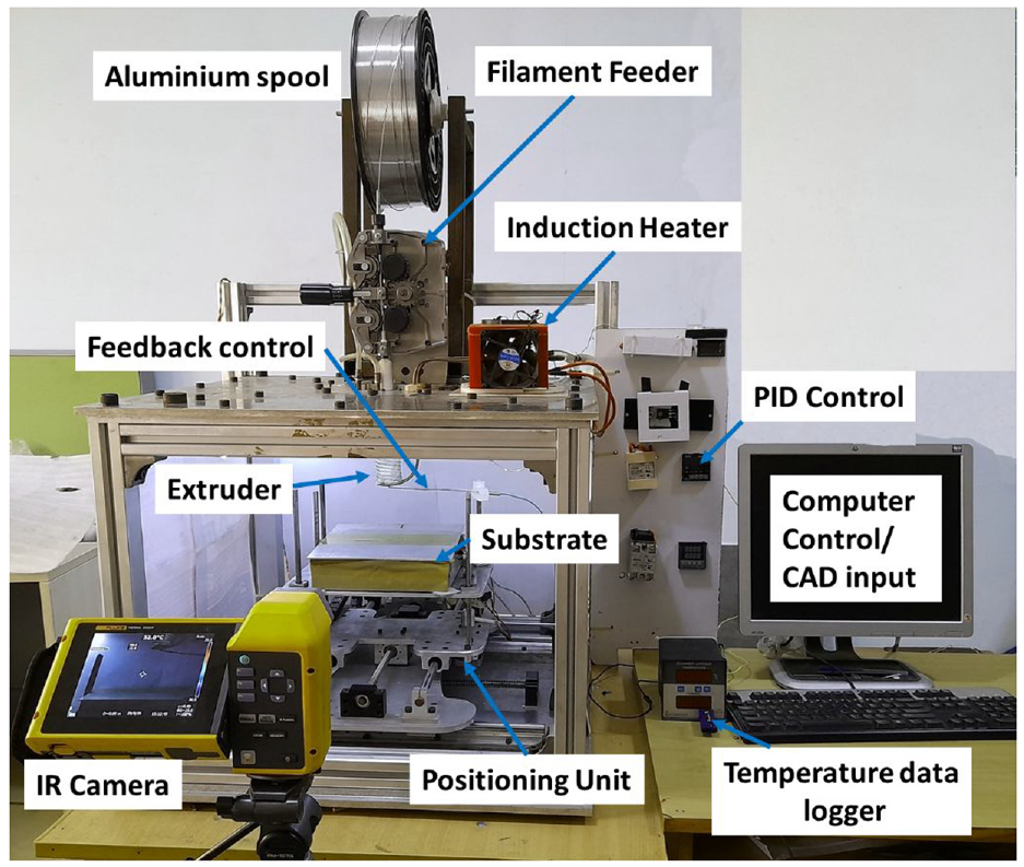
The working of IH based material extrusion is explained through schematic in Figure 1. The main components in the IH based wire AM system are filament feeding system, extruder head, an induction heater with coil arrangement and cooling system, positioning unit which translates the build platform with substrate, Proportional Integral Derivative (PID) based temperature controller, computer control featuring user interface module, and a Computer Aided Design (CAD) data input as shown in Figure 2. An induction heater of 1 kW capacity has been used with a customized coil arrangement. The customized coil features nine number of coil turns of tube diameter 5 mm. The coil radius and coil length was kept at 15 and 50 mm respectively of inductance 1.13 μH. The coil configuration is based on the Cast Iron (CI) extruder dimensions having diameter of 12 mm and length of 55 mm. These coil parameter selection gives a maximum magnetic field strength for rapid heating and achieving the desired temperature in the extruder. Nine number of turns are selected on the basis of the preliminary results of a simulation study, where it was found that the nine number of coil turns gives a desired extruder temperature profile at an efficient heating rate.
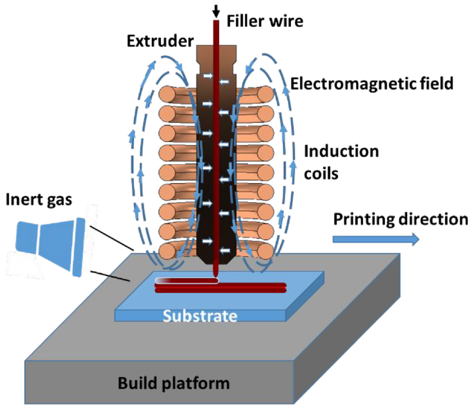
Working principle of induction heating based wire AM process.
Developed induction heating based wire additive manufacturing system.
The solid metal filament is fed coaxially into the extruder and the semi-solid material is extruded from the tip end. The tip of the extruder head is kept outside (approximately 4 mm) the coils. The coil is fabricated such that there exist three temperature zones of the filament material inside the extruder classified as solid fed, transition, and liquid state. The heat profile inside the extruder is governed by formulation of skin depth that depends on the frequency of the supplied current, resistivity, and relative permeability of the heated material (i.e. extruder). 36
The basic principle of material extrusion using IH method is pictorially illustrated in Figure 1. The schematic working of IH to melt and deposit material shows that the high current oscillation frequency of around 100 kHz is supplied to the coil to generate the electromagnetic field around the coil. When the electrically conductive material extruder is exposed to the altering magnetic field, eddy currents are induced on its surface. The material properties like high electrical resistance and thermal conductivity enhances the heating rate of the material. 37 The induced eddy currents in a rapid changing direction enables the molecules of the elective conductive extruder to change direction. This results in heating of the extruder surface. The eddy currents are dominantly responsible for the heating phenomena. 18 The heating of the body is rapid and the temperature of the body rises rapidly in a few seconds. The heating of the body is then controlled by introducing a PID and a thermocouple. A type-k thermocouple is placed at a position in the extruder, which upon a certain degree of temperature (∼595°C) cut off the supplies from the induction heater and maintains the temperature of the extruder. A SESTOS make PID controller is employed for the work. The thermocouple signal is used to turn switches of the PID relay, which cut off the power supply of the heater. Thus, the extruder temperature is maintained at a set temperature.
The in-house developed experimental setup capability to process low melting point metal and alloys is investigated by incorporating IH energy source to metal-additive manufacturing. The developed system has an envelope size of 600 × 600 × 600 mm3 while the build volume is 150 × 150 × 120 mm3. In the developed novel AM system, the build platform movement is provided in the three directions (X, Y, and Z) while the extruder head assembly is stationary and fixed to the inside upper part frame body of system. The digital data obtained after slicing the CAD part model is transferred to the computer numeric control based positioning controller, which moves the axis according to the contour profile. Then the part deposition is performed in a bottom up approach, wherein the extruder lay down the semi-solid material on the moving substrate layer by layer in lateral direction. Upon successful completion of a layer, the build platform descends to a defined step distance and thus part are completed by adding layers as per the prototyping needs. It is to be noted that the substrate heating is performed by using the heated build platform. The resistance heating method has been used for substrate heating. Substrate heating facilitates mechanical bonding of the initial layers with the substrate, thermal, and microstructural uniformity in the layers and the part. 38
Materials and experiment
Material
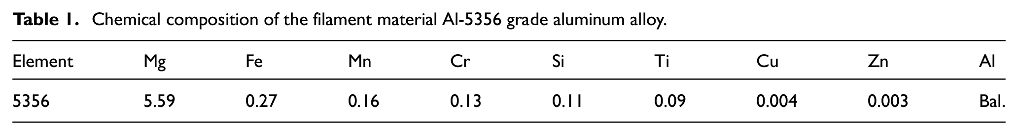
A wire filament of 1.6 mm diameter of Al-5356 grade (Al-Mg alloy) is utilized as a feedstock material to be extruded and deposited on an aluminum substrate. Aluminum grade (Al-5000 series) material of 100 × 100 × 3 mm dimension is chosen as substrate, which is cleaned using ethanol prior to the printing process. The temperature 575°C–585°C is ideal to maintain liquid fraction and viscosity of the aluminum alloy to flow in die cavity under pressure. 39 The CI is used as an extruder material, the selection of CI material is done owing to the high electrical resistivity, magnetic permeability, and melting temperature. 40 The composition of the filament wire is listed in Table 1.
Chemical composition of the filament material Al-5356 grade aluminum alloy.
Experiment setup and description
The experiments in the study are performed on the in house developed IH based material extrusion AM setup. The extruder of CI material is heated using the induction heating. Later, the feedstock material in wire filament form is fed coaxially through the heated extruder which then conductively transfer the heat to filament and transforms it into semi solid form. The semi-solid material is then deposited layer by layer as per the prototyping requisites. The basic components of the system embraces the extruder head unit, positioning unit, material feeder unit, build platform, and induction heating unit. The schematic view of the system is illustrated in Figure 3. A 1 kW zero volt switching induction heater is used to fed current intensity (∼200 A) and current frequency (∼100 kHz) to the customized coil. The major process parameters involved are the induction heating parameters and the deposition parameters. The experiment were performed with the following input parameter condition: coil current (I/A), supply voltage (U/V), current frequency (f/Hz), wire filament feed-rate (Ws/mm·s−1), printing speed (Ps/mm·s−1), extruder temperature (Text/°C), substrate temperature (Tsubs/°C), and substrate nozzle gap (SOD/mm).
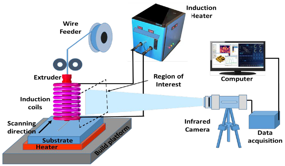
Schematic diagram of IR camera setup in IH based AM system.
Infrared thermography
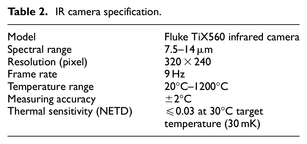
Infrared camera employed to capture videos in the work is TiX560 model from Fluke Corporation. The description of the IR camera specification can be seen in Table 2. The working spectral range of the fluke model was 7.5–14 µm. A front view perspective during the image acquisition is represented in Figure 3. The camera faces normal to the y-z plane or front of the build volume and the distance between the camera sensor and processing zone is set at 0.47 m to monitor thermal field variation. Before the thermal imaging of the process, the emissivity for the material is calibrated. For this, the IR imaging in the process zone is performed and simultaneously the thermocouple data are taken. With Fluke IR camera, the process window is identified. The temperature measurement range of this type-k thermocouples was 0°C–1300°C with 1 Hz data acquisition rate and the accuracy up to ±0.75%.
IR camera specification.
The principle of the IR temperature measurement is postulated as Stefan-Boltzmann law. 33 The emissivity of a surface varies with the temperature and its surface morphology. 41 A real surface can take the value of emissivity between 0 and 1, depending on its ability to emit radiated energy to it. 42 Seppala and Migler 43 used an IR camera with correction of IR intensity. A very common practice with the researchers is to undertake the value of emissivity as constant and validating it with the intrusion method of temperature measurement using thermocouple.
A constant surface emissivity of 0.1 is chosen for aluminum alloy in its processing during induction heating, although it changes with temperature and oxidation that occurs during heating. 39 In order to measure the temperature precisely, the emissivity of the deposited part should be obtained first. As the region of interest in the study includes the cast iron extruder, glass fiber insulated coils, substrate, and the extruded material, different emissivity of different material types comes into picture during the IR study. Its implementation are discussed in the Section 5. Figure 4 shows the emissivity calibration methodology adopted in the IR imaging of the extruder heating. Radiometric data taken from the IR imager is then post processed to obtain the results.
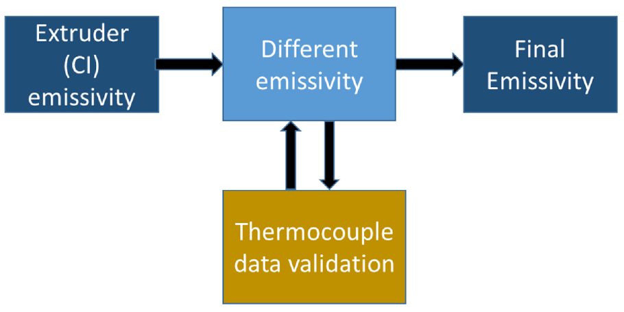
Calibration of emissivity in IH heating.
Results and discussion
Thermal imaging of extruder
The IR imaging during the extruder heating is performed, for this IR laser sensor is focussed on the extruder tip and different emissivity of the material are set. Simultaneously, the intrusive based method is used to measure temperature, for this a thermocouple is inserted at the position akin to point of temperature measurement of IR sensor. The emissivity of the heated extruder is calibrated by adjusting five different values of the emissivity between 0.76 and 0.84. An intrusion of thermocouple is made at a position on extruder’s surface. Figure 5(a) shows the results from the IR imaging and the temperature time plot of extruder heating is monitored when different emissivity values are set. The temperature using thermocouple data is also plotted during the heating of extruder. It can be interpreted from the figure that the emissivity value of 0.80 closely relates to the thermocouple reading in the experiments temperature range. Hence, the emissivity value can be fixed for cast iron extruder material and can be further used in the experiments. The IR image of the heated extruder can be seen in Figure 5(b). The respective figure shows the heat concentration at the extruder tip. This can be correlated with the edge effect, which is due to the distortion of the electromagnetic field in the area near to edges.44,45
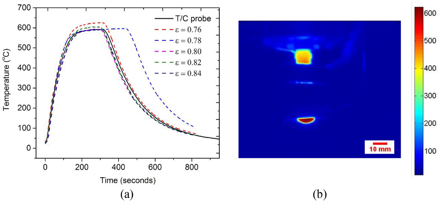
(a) Variation of temperature with time for different emissivity (ε) values and (b) IR imaging of extruder heating (temperature in °C).
Effect of substrate vicinity on extruder temperature
In the second study, the IR imaging is performed to elucidate the effect of substrate vicinity on the thermal cycle of extruder heating. For the resulting experiments, the stand-off distance (SOD) between the extruder tip and substrate is varied as 1.0, 1.5, and 2.0 mm. A cold substrate is considered for the following study. The effect of substrate placement from the extruder tip is shown in Figure 6. As can be referred from Figure 7 that the extruder tip (P2) temperature increases as the SOD is increased. The tip maintains an average hold temperature of 608°C, 597°C, and 567°C when the SOD is kept at 2.0, 1.5, and 1.0 mm respectively. The variation in SOD effects the extruder temperature. The effect can be justified as the proximity effect 36 in which the magnetic field is distributed to the substrate when the SOD is less, causing the tip temperature to drop. The reduction in tip temperature below the reference temperature causes the problem in the material extrusion from the extruder tip. Also, larger SOD would lead to the non-uniformity in the track printing. Therefore for printing process, a suitable cut off temperature (at cut-off position P1 in Figure 7) and SOD, should be maintained so that the aluminum material can be efficiently ejected and printed.
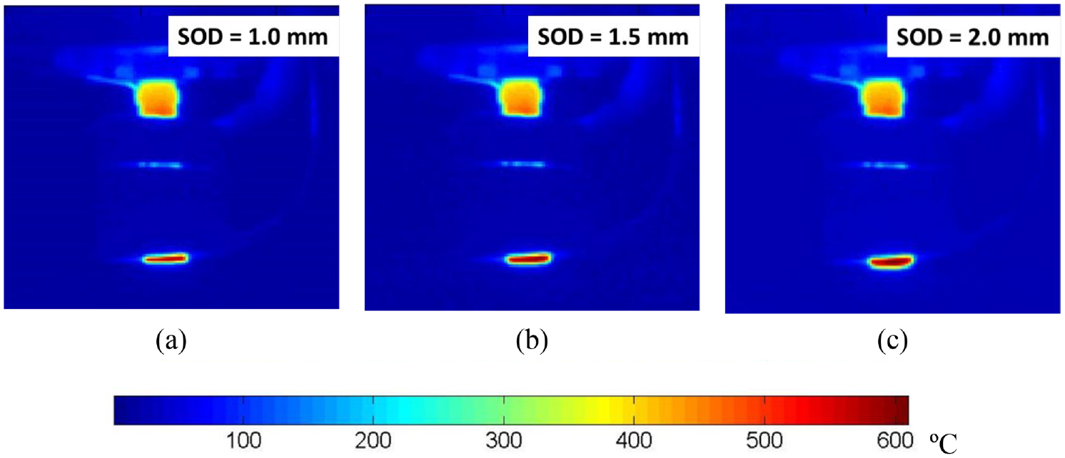
Thermal image of the extruder after 250 s of heating at different stand-off distance, SOD: (a) 1.0 mm, (b) 1.5 mm, and(c) 2.0 mm.
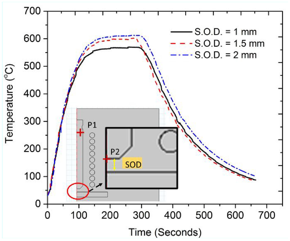
Temperature to time variation at extruder tip (P2) with varying SOD.
Thermal analysis of the extruded drop
The processing of aluminum has been performed in the semi-solid state. A free drop ejection test is carried to see the evolution of the extruded aluminum drop. In Figure 8, the IR imaging has been performed and the droplet evolution can be seen at 0, 5, 10, 15, 20, and 30 s. The size of the extruded drop increases with the time. The notion to carry the drop study is to ascertain the semi-solid processing nature of the implemented novel AM technology. The average and the peak temperature of the drop is retrieved from the IR images of drop at different time instances as shown in Figure 9. It can be clearly seen that the drop peak temperature is maintained between 556°C and 600°C. It is noteworthy to mention that the peak temperature in the drop exist at the drop ejection point. The temperature of the drop varies significantly along its length due to the high temperature gradients and the semi-solid material solidifies quickly. In actual, a stand-off distance is maintained between the extruder tip and substrate and the drop is printed on the substrate. The stand-off distance and the substrate speed decides the time and thereby the length of the drop until which the drop is printed as layer. Ideally in the case of fused coated deposition, the stand-off distance is kept at 1.1 times the extruder nozzle diameter13,46 which in presented study is 1.5 mm. Therefore, the average temperature of the drop is maintained above 500°C, for the layer deposition cases. Prolong exposure before deposition and larger stand-off distance reduces the average temperature of the drop causing the flowability of the extruded drop to reduce, since the gas-liquid interface increases and morphological stability of the drop is affected.
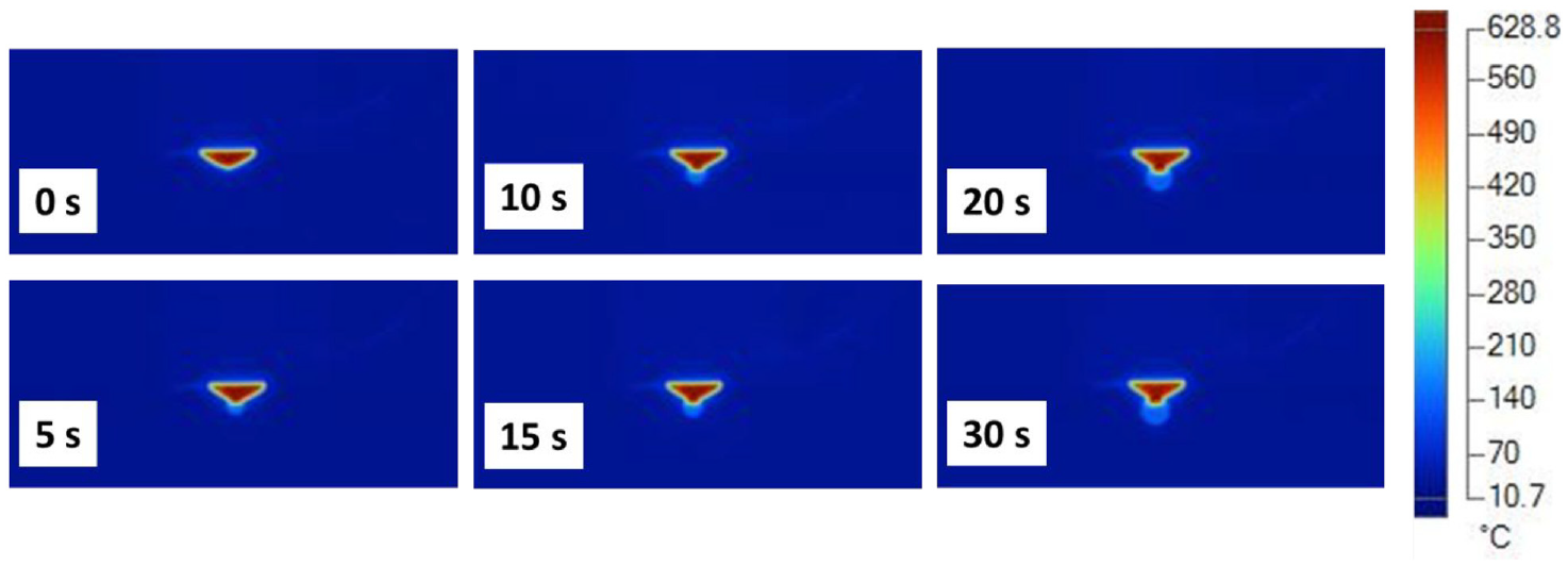
Thermal image of the free droplet evolution at distinct time.
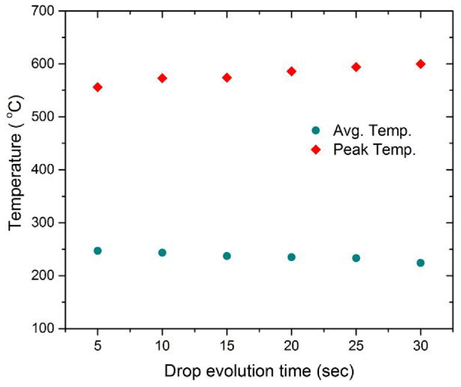
Variation of free droplet temperature with drop evolution time.
Thermal analysis of the multi-layer deposition
The thermal trend in the layers is manifested by post processing the IR thermography in the single pass – multi-layer deposition. The temperature distribution is shown for the first and the second layer in Figure 10(a) and (b) respectively. In the layer deposition direction for the first layer, the temperature profile for process parameters (printing speed 120 mm/min, filament feed rate 120 mm/min and extruder temperature 595°C, and stand-off distance 1.8 mm) shows the maximum temperature of the layer at the instant of completion of first layer is 615°C. For the first layer, the moving direction of substrate is from left to right. It can be seen that the temperature reduces gradually and the layer comes under thermal equilibrium as the extruder nozzle passes over it, after the deposition. The noted average temperature of the extruder is 656°C. In Figure 10(b), which shows the thermal nature after the second layer completion. It can be seen that the heat is retained by the previous deposited layer and again a gradual cooling of the layer is seen. The accuracy of temperature acquisition is governed by the emissivity which is further thermal and spectral dependent.

Temperature distribution during the (a) first layer and (b) second layer deposition.
The temperature profile for the multi-layer print is plotted in Figure 11, where the temperature variation along the length of the printed layer (90 mm) is shown. The noted temperature is at the instance of completion of each layer. As can be seen the layers (L-1, L-2, L-3, and L-4) instantaneous temperature is at end of layer completion is at 556°C. A steeper thermal gradient is observed in the layers at the position of fresh extrusion of material.
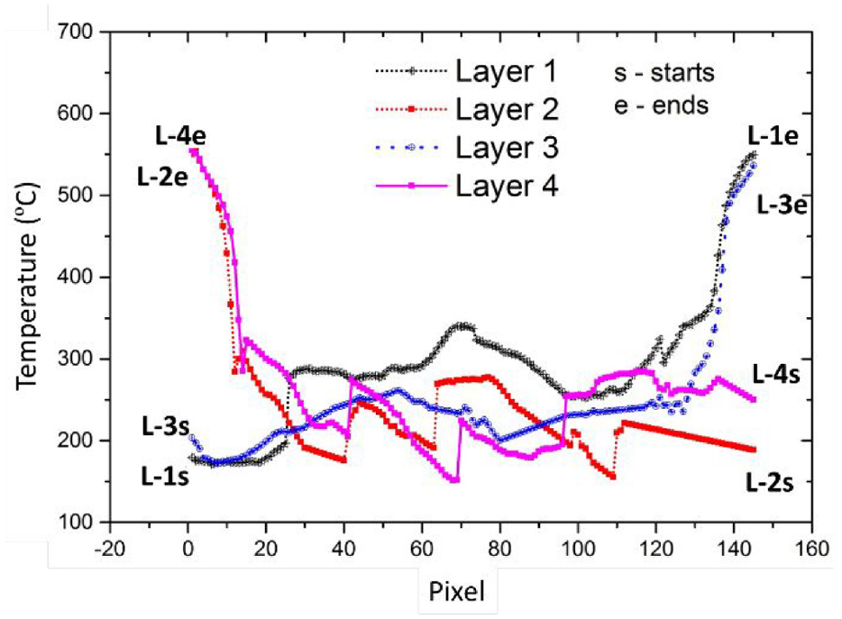
Temperature profile in the layers, after completion of each layer.
The variation of temperature along the extruder axis in the direction opposite to layering are reported in Figure 12. These results are measured after the completion of four layers. At the instant of completion of fourth layer, the extruder is positioned just above the layer as shown in the schematic in Figure 12. The temperature of deposited layers across the line 1 varies from 551°C to 308°C. This has been achieved due to the substrate heating which was kept at 250°C, this resist the further transportation of the heat to the substrate. The influence to substrate heating can be seen on the base layers, which is holding the temperature above 300°C. Also, the heat penetration from the incoming material and extruder can be seen at the end of line 1 (as shown in Figure 12). Thus, the thermal cycles effect the layer temperature and hence, the temperature of the first few layers varies between 390°C and 308°C. The depicted temperature variation measurement shows the thermal gradient of 323°C/mm in the upper layer and 57.4°C/mm in the base layer. Figure 13(a) shows the printing on IH based metal AM system and a four layer extruded contour part performed using the developed novel AM system (Figure 13(b)).
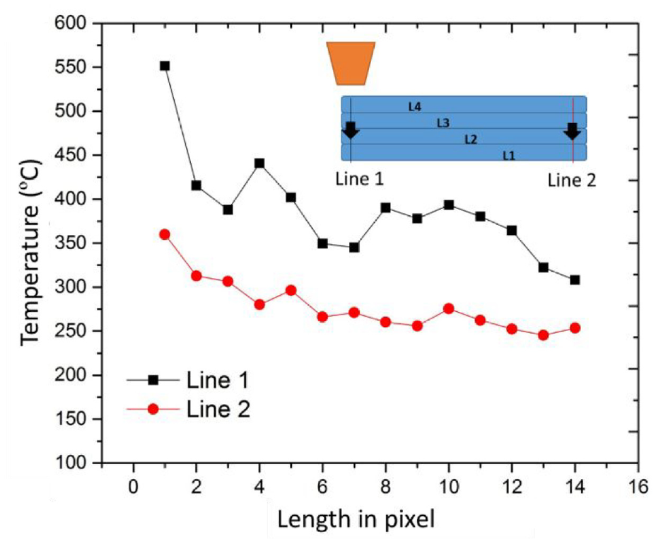
Temperature variation on the layers along the build direction (after the four layer deposition).
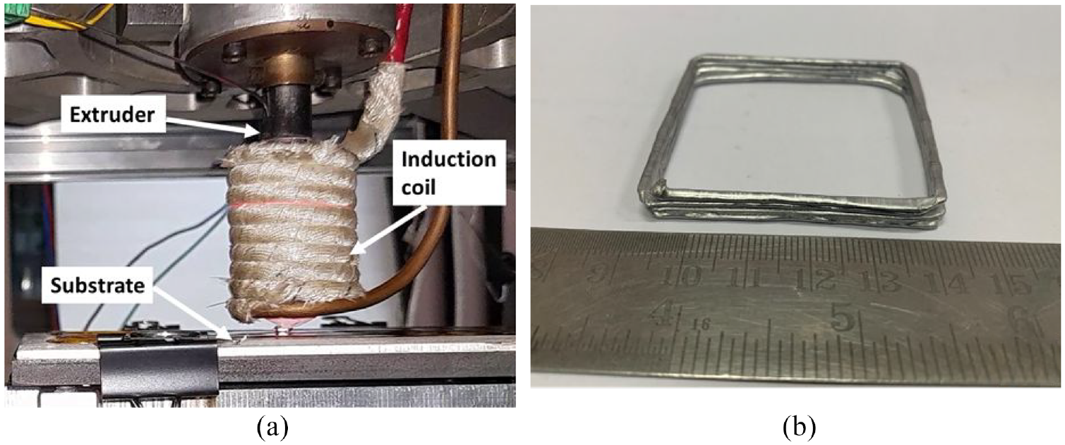
(a) Printing on the IH based metal AM system and (b) a four layer contour part (Al).
Conclusion
The research work presents the development of a novel induction-based material extrusion system contributing to the scope of processing metals in the material extrusion category of AM technologies. A description of in house development and its feasibility are detailed in this work. A thermal analysis is conducted to elaborate the insights during the heating of extruder and thereby transition of solid filament material into a multiple printed layers. Process parameters like extruder temperature, filament feed rate, substrate speed, and substrate temperature are considered. Aluminum material (Al-5356) is tested for the current purpose. An in situ IR imaging was implemented to elucidate the insights of thermal behavior during extruder heating and material ejection. The study highlights the fundamental issues in the extrusion deposition using induction heating. Some major conclusions drawn from the study are:
Induction heating has been implemented as a source to extrude and deposit the filament material into layers and it has been successfully performed. A comprehensive in situ IR thermography has been done and the results are validated with the thermocouple data for the extruder heating.
The position of substrate with the extruder tip (SOD) effects the extruder temperature. The extruder tip temperature increases with an increase in the SOD. As stated in the above findings, a suitable temperature should be maintained at extruder tip, so that extruded aluminum material can be efficiently ejected.
During the multi-layer deposition the substrate heating have a vital effect on the base layers. A lower thermal gradient is achieved on heating the substrate, the thermal transfer between the layers assist in layer adhesion. The depicted thermal gradient of 323°C/mm is seen in the upper layer and 57.4°C/mm in the base layer.
The study can be further amalgamated with the part printing and can be further utilized to improve the deposition quality of the printed part.
Footnotes
Declaration of conflicting interests
The author(s) declared no potential conflicts of interest with respect to the research, authorship, and/or publication of this article.
Funding
The author(s) disclosed receipt of the following financial support for the research, authorship, and/or publication of this article: The author would like to thanks DST/TDT/AMT, India for providing financial support. Present work has been carried out under the DST/TDT/AMT sponsored project “Development of induction conduction based material deposition system for metal additive manufacturing” (DST/TDT/AMT/2017/119/G).