
Abstract
Determination of optimal parameters of cutting tool is one of the most significant factors in any operation planning of metal elements, especially in micro-milling process. This article presents an optimization procedure, based on genetic algorithms, to optimize some parameters related to micro-milling tool including number of teeth, shank diameter, fluted section diameter, shank length, taper length, and length of fluted section. The aim of this optimization is maximizing the minimum value of cutting depth on the border of stability lobe diagrams, which is called allowable cutting depth, for chatter-free machining. Cutting tool is modeled as a three-dimensional spinning cantilever Timoshenko beam based on strain gradient elasticity theory. Structural nonlinearity, gyroscopic moment, rotary inertia, and velocity-dependent process damping are also considered in the cutting tool model. The values of natural frequency, damping ratio, and material length scale of the micro-milling tool are calculated using a system identification based on genetic algorithm to match the analytical response with recorded experimental vibration signal. Using beam model, the allowable cutting depth is increased in the optimization process for a specific range of spindle speed to avoid the chatter phenomenon. Analytical study of micro-milling process stability is carried out to determine the cost function of the genetic algorithm. A plot of the greatest fitness in each generation is sketched. In addition, stability lobe diagrams before and after optimization process are presented to show the efficiency of the optimized micro-milling tool. In the presented examples, the results of genetic algorithm may lead to design or find a micro-milling tool that its acceptable cutting depth increases up to 1.9313 times.
Keywords
Introduction
The most frequently used technique in manufacturing is milling that is the machining process of materials.
1
Micro-milling is a significant operation of mechanical micro-machining, with realistic application in mold and die, automotive, aerospace, military, biomedical, and micro-electronics packaging industries. Commercially available micro-milling tools have the tool diameter ranging
Optimization of different parameters related to milling tools and determination of optimization objective or optimization criterion are very important in the design phase of milling tools. Tolouei-Rad and Bidhendi 27 determined optimal machining factors for milling processes by applying an optimization system. Choudhury and Rao 28 developed the optimized values of velocity and feed rate for improving cutting operation. Sönmez et al. 29 studied an optimization strategy to maximizing production rate of multi-pass milling processes. Shunmugam et al. 30 used a genetic algorithm (GA) to reduce production cost of a multi-pass face-milling, where the number of passes, depth of cut in each pass, spindle speed, and feed rate were the decision variables. Baek et al. 31 optimized the feed rate in a face-milling process by applying a surface roughness model. Suresh et al. 32 predicted and optimized surface roughness by developing a mathematical model and GAs, respectively. Tandon et al. 33 optimized a numerical control (NC) end milling by applying a new evolutionary computation procedure. Juan et al. 34 modeled rough machining of high-speed milling processes using a polynomial network and minimized the production cost of that. Kim and Ramulu 35 applied an optimization approach on the drilling operation to increase hole property and decrease drilling cost. Wang et al. 36 optimized feed rate and spindle speed to reduce the time of production in plain milling. A number of researchers37–39 have scrutinized the machining operation by applying the Taguchi method to optimize machining parameters such as cutting velocity, feed rate, and cutting depth taking surface roughness as an objective function. Kılıckap et al. 40 developed the relationship between cutting parameters such as cutting speeds, feed rate, and depth of cut, and optimization techniques as response surface methodology and artificial neural network for cutting forces, surface roughness, and tool wear in the milling of Ti-6242S alloy.
Regenerative chatter that is a kind of unstable self-generative vibrations is an undesired phenomenon that can occur during micro/macro-milling operations. Incidence of chatter may lead to poor surface finish and limits the efficiency and productivity of machining processes. It comes from coupling between cutting force and vibration of tool/work-piece system. Several stability models have been considered in previous publications, where mostly the stability limit in terms of axial depth of cut is emphasized for chatter-free machining. 41 Here, the minimum value of cutting depth in stability lobe diagram (SLD) with avoidance of regenerative chatter phenomenon in a certain spindle speed span is called allowable cutting depth. Consequently, maximizing the allowable depth of cut to chatter-free machining is one of the principal factors in micro-milling process, which significantly affects the cost, time, and efficiency of production processes. The determination of optimal parameters of micro-milling tool containing number of teeth, shank diameter, diameter of fluted section, shank length, taper length, and length of fluted section is a very significant problem to maximize the allowable cutting depth. This optimization may lead to design an optimum geometry of a micro-milling tool, which has maximum allowable cutting depth without damage to tool. In practice, all commercially available micro-milling tools on the market have a specific geometry. Using an optimization method, operators can order a micro-tool design with optimal geometry for a specific machining, or at least select a micro-tool that its geometry is close to the optimal values.
One aim of the current work is the system identification based on time domain technique. The values of natural frequency, damping ratio, and material length scale are calculated from matching the analytical response with recorded vibration signal using an optimization algorithm. To the best of the authors’ knowledge, this method of size scale calculation has not yet been presented in any effort. Therefore, one of the novelties of this study is the calculation of material length scale using system identification. The main purpose of this study is the optimization of a micro-milling tool geometry. The allowable cutting depth is selected as a criterion function. Analytical study of a micro-milling process stability is necessary to determine the objective function of this optimization algorithm. For this purpose, a nonlinear three-dimensional (3D) spinning cantilever Timoshenko beam based on strain gradient elasticity theory is used for modeling the cutting tool by considering structural nonlinearity, gyroscopic moment, rotary inertia, and velocity-dependent process damping. Accordingly, another major novelty is the analytical study of micro-milling process stability to determine the objective function of the tool design optimization. In the literature, the GA is one of the pioneer heuristic algorithms that is the most experimented optimization algorithm due to its simplicity and global perspective. 42 Therefore, the GA is used as optimization algorithm in this study.
Methodology
In the current research, the mathematical model is derived by applying mode-summation method (MSM) and then method of multiple scales (MMS) on the formulation of a nonlinear 3D spinning cantilever Timoshenko beam based on strain gradient elasticity theory. The micro-milling operation mathematical model is derived to find the SLD, which is based on cutting depth versus spindle speed. The minimum value of the cutting depth on the border of corresponding SLD has been used as a criterion function. The features of tool including number of teeth N, shank diameter
Mathematical formulation
A 3D rotating fixed-free non-uniform Timoshenko beam, as presented in Figure 1, is employed to derive the equations of motion of the micro-milling tool.
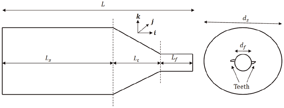
Schematic of a micro-milling tool contains shank, taper, and fluted parts.
The tool turns around its longitudinal axis at a constant spindle speed
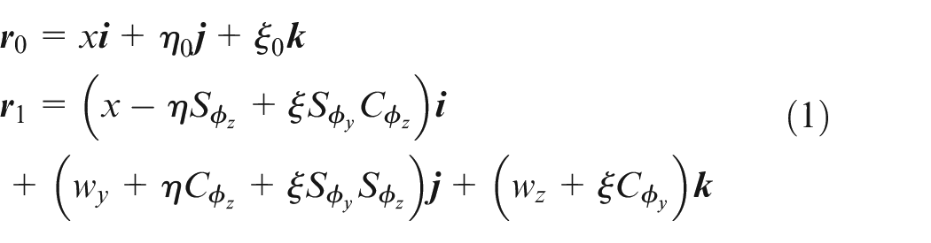
Here, the characters
For the non-axisymmetric twisted geometry of the tip section of the micro-milling tool, the moments of area relative to
For the tool with kinetic energy
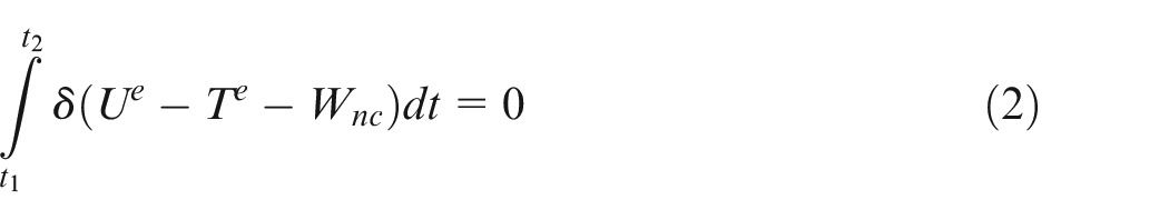
The strain energy of the tool is as follows26,43,44
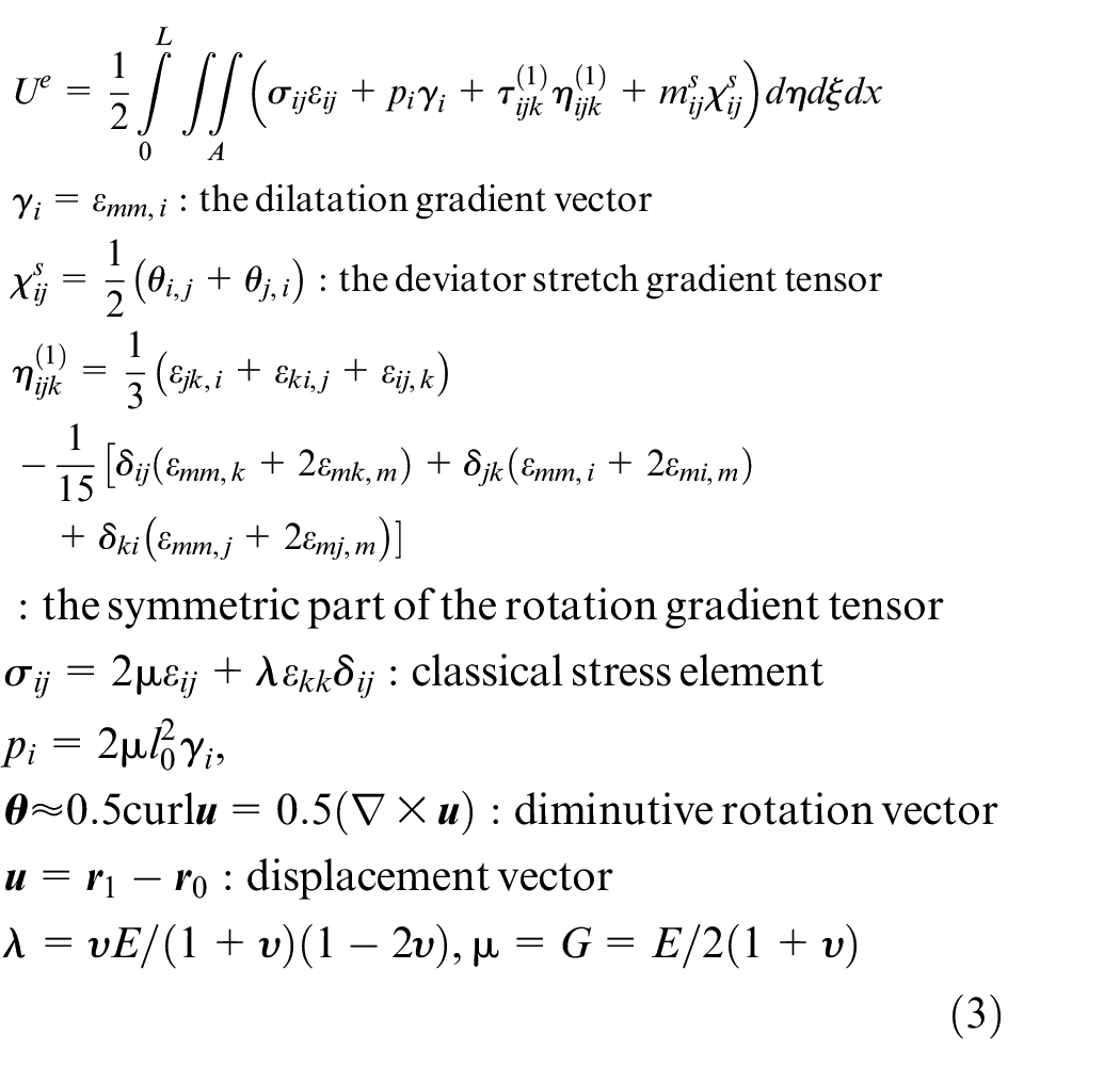
where E, G,
The kinetic energy of the tool can be presented as follows 26
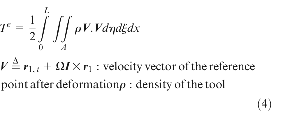
where
where a,
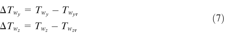
The third-order nonlinear delay partial deferential equations (DPDEs) can be derived by substituting
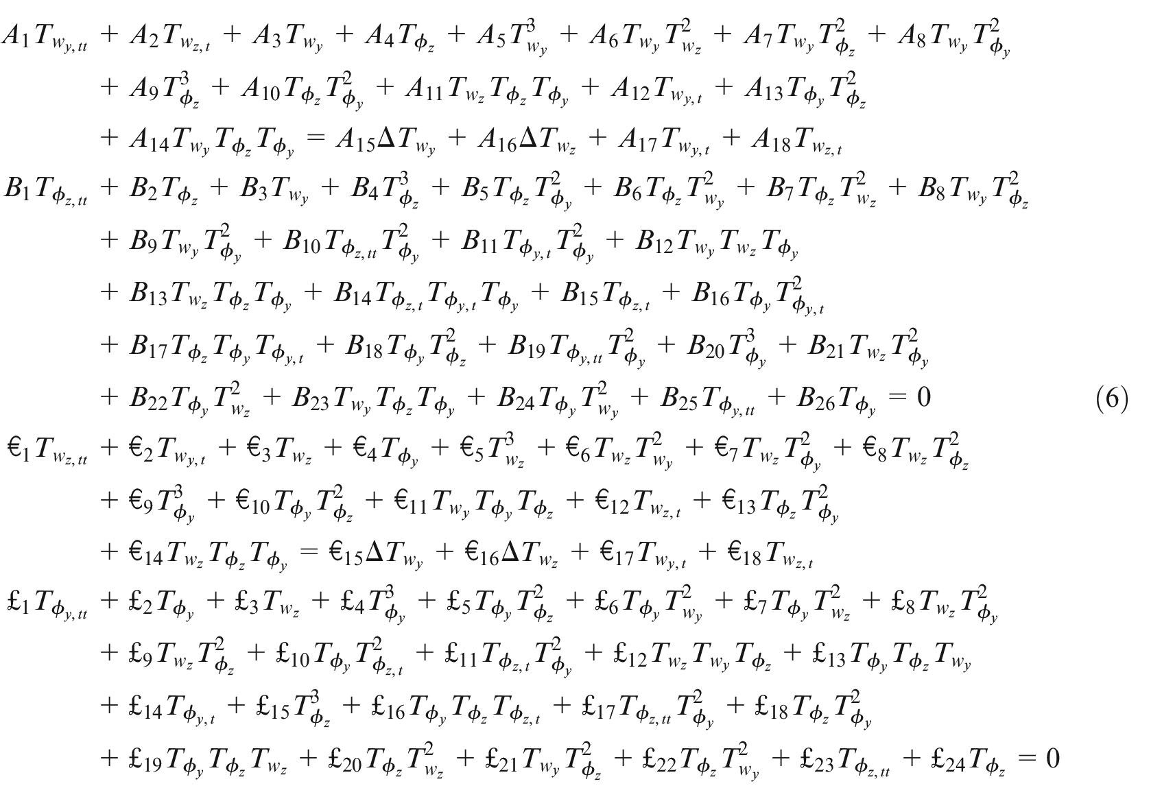
in which
where
Curve fitting process of area second moments.
For plotting SLD, the analytical solution of proposed model can be derived by applying MMS on the governing DODEs. 25
Optimization procedure
Optimization procedure is one of the significant aims of manufacturing systems. The GAs are robust and adaptive schemes, which are effectively applied for solving optimization problems. The GA is a heuristic search technique used in artificial intelligence and computing. This method is based on the theory of natural selection and evolutionary biology. These are sagacious utilization of random search provided with historical data to lead the search into the area of improved efficiency in solution region. To ensure optimization results, the optimization process is executed 20 times and the best result is considered. In addition, by reducing or increasing the constraint range, it has reached the same answers again, indicating that the answers are optimal.
In order to maximize the allowable cutting depth to chatter-free micro-milling process, it is necessary to determine the objective and constraint functions as follows
where
The flow diagram of presented GA to find the best tool geometry with maximum allowable cutting depth.
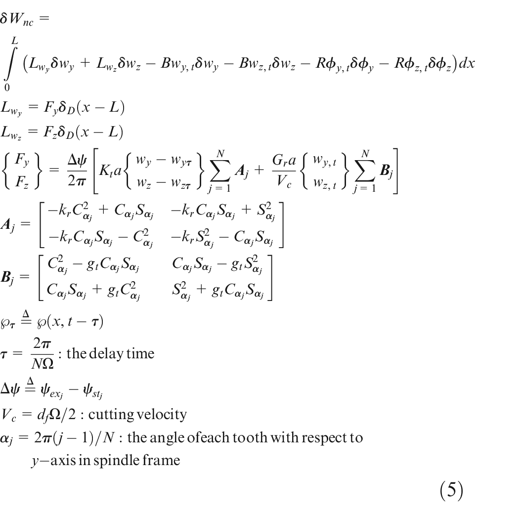
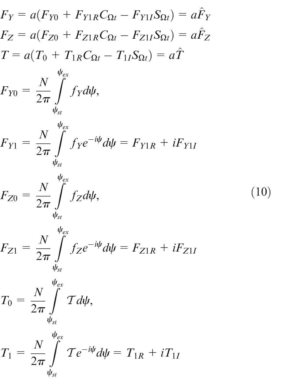
As presented in equation (5), average regenerative cutting forces are considered in the dynamic model using zero-order solution. For the case of forced vibration, dynamic chip load and its corresponding force with respect to fixed reference framework XYZ are described as follows 46
where
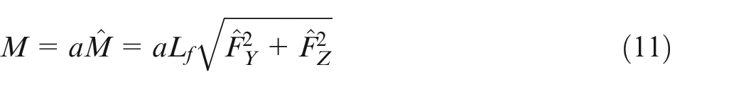
In addition, the maximum bending moment occurs at the fluted part origin is
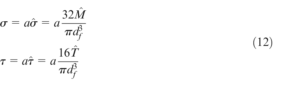
Consequently, normal stress
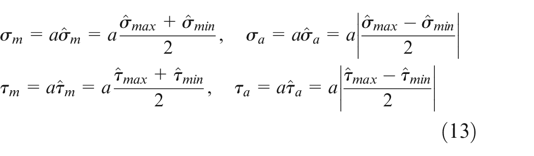
If the largest stresses are
The von Mises stress is often used to calculate yielding of materials under complex loading 47 as follows
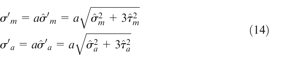
Here, the Goodman failure criterion is used to find
where
System identification
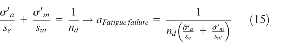
In this section, some parameters such as natural frequency, damping ratio, and the values of material length scale of a micro-milling tool are calculated by applying the time domain technique to the system identification test. The specifications of the cutting tool used for system identification test are presented in Table 1.
Specifications of cutting tool used for system identification test.
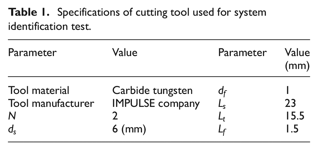
The time domain technique requires an input to be applied to the cutting tool. In the current experiment, a hammer is used to generate an impact force at the free end of the cutting tool, which in fact stimulates the first bending mode of the structure vibration. The output vibrations are recorded at the shank by an accelerometer sensor (see Figure 4(a)).
Experimental setup (a) for system identification test and (b) for chatter test of micro-milling process.
The specifications of experiment equipments are tabulated in Table 2.
The specifications of experiment equipments.
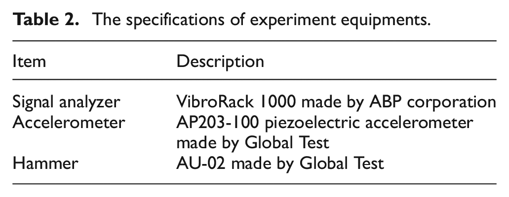
Figure 5 shows a sample of recorded experimental vibration signal of the tool-sensor system.
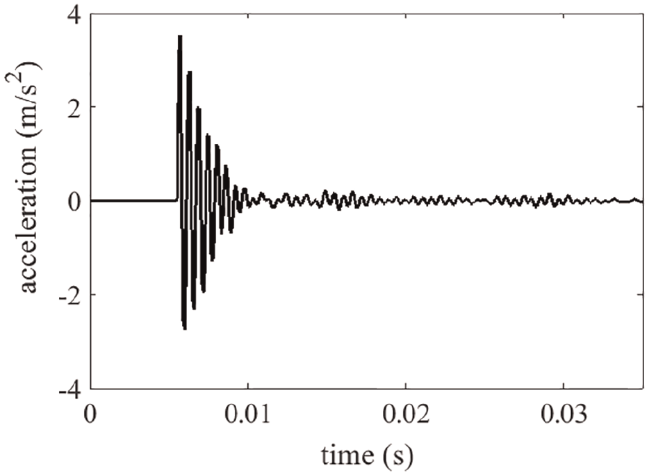
The vibration time response of the tool-sensor system recorded by accelerometer sensor.
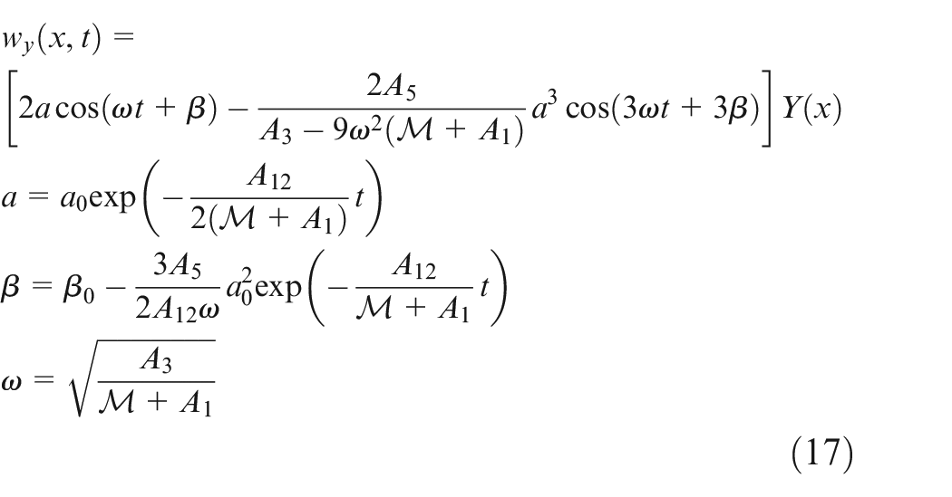
In order to identify the system parameters, the nonlinear governing PDE for bending motion
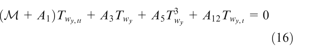
where
The system parameters including damping ratio and the values of material length scale, assuming that all of them are equal
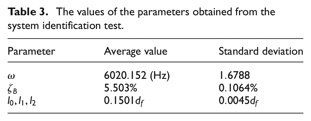
The values of the parameters obtained from the system identification test.
Here, the RMSE is used to measure the differences between oscillation values predicted by presented model (equation (17)) and the oscillation values observed from experimental test illustrated in Figure 5. Indeed, this statistic parameter is a quadratic scoring rule that measures the average magnitude of the error. The RMSE can take on any non-negative value and a magnitude nearer to zero representing that a better fit is accounted by the model. The cost function value in each generation is illustrated in Figure 6 during the searching process to achieve the minimum value of the RMSE. In addition, the values of other statistics parameters, such as the sum of squares due to error (SSE) and the coefficient of determination so-called R-square that is usually used for evaluating the model, are presented in Figure 6 for the optimized model.
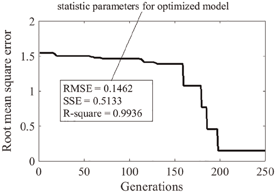
Variation of RMSE as the objective function versus number of generations for system identification.
The analytical response, obtained based on the system parameters in Table 3, is compared with the experimental answer in Figure 7 to show the precision of presented system identification.
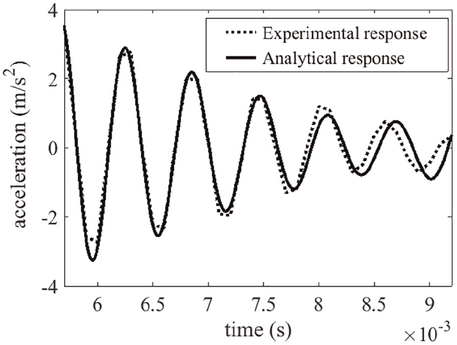
Comparison of analytical and experimental response at the end of the tool shank.
Results and discussion
Validation
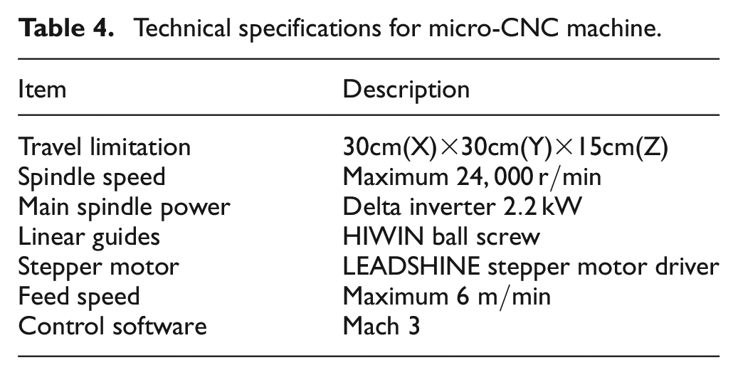
To verify the nonlinear continuum beam model of micro-milling, a set of experimental chatter tests are conducted on an in-house micro-computer numerical control (CNC) machine with the previous mentioned micro-milling tool (see Figure 4(b)). Technical specifications of the CNC machine are tabulated in Table 4.
Technical specifications for micro-CNC machine.
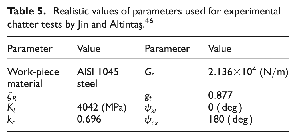
The other basic parameters utilized for all experimental tests are tabulated in Table 5.
Realistic values of parameters used for experimental chatter tests by Jin and Altintaş. 46
The calculated SLD is evaluated with the chatter test data in Figure 8. The comparisons between the experimental and calculated results show good agreement.
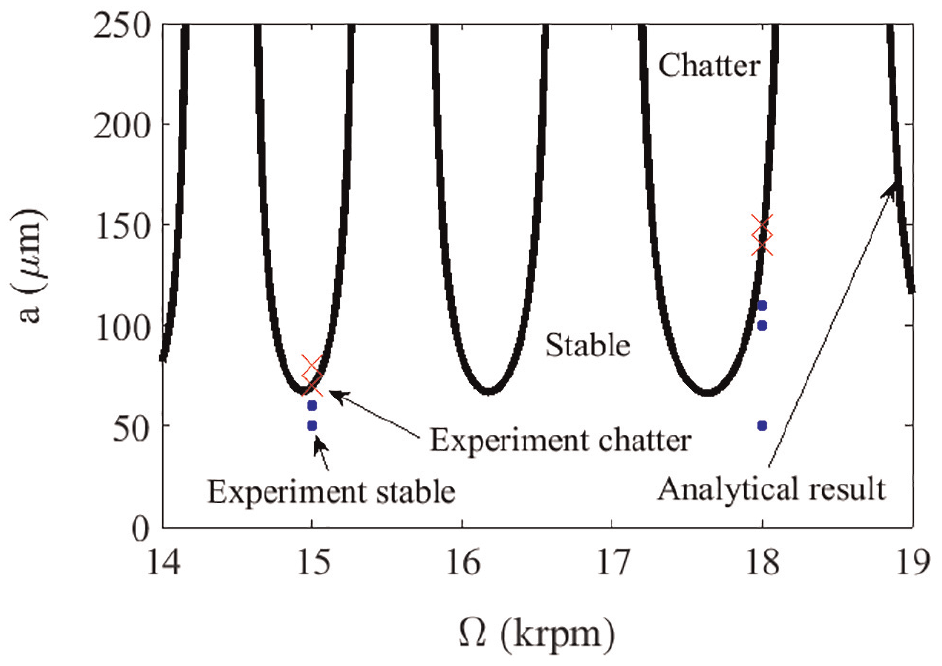
Comparison between predicted lobe diagrams and the experimental chatter test data.
Optimization: example 1
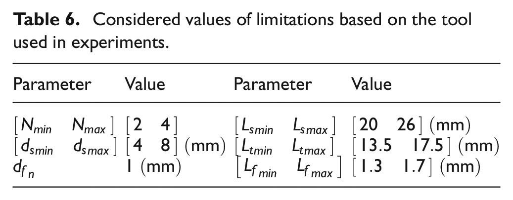
For a realistic example of optimization, the micro-milling process mentioned in previous sub-section is selected. It is well known that a considerable generation size improves the efficiency of optimization process and consequently diminishes the variations of premature convergence. For that reason, various numbers of generations are checked to get appropriate convergence to optimized value. To guarantee the correctness of the findings, the limitation values corresponding to constraint functions are considered in a specific range around realistic values of Table 1 (see Table 6).
Considered values of limitations based on the tool used in experiments.
Here, the factor of safety
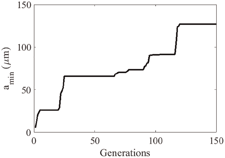
Variation of objective function with number of generations based on the tool used in experiments.
Figure 9 shows that the best possible value of optimum cutting depth obtained from GA is
The values of variables in the optimum situation based on the tool used in experiments.
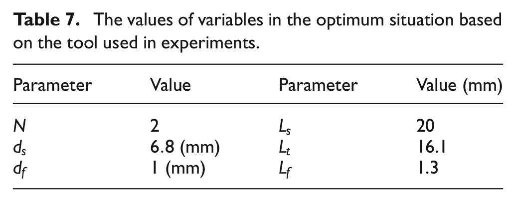
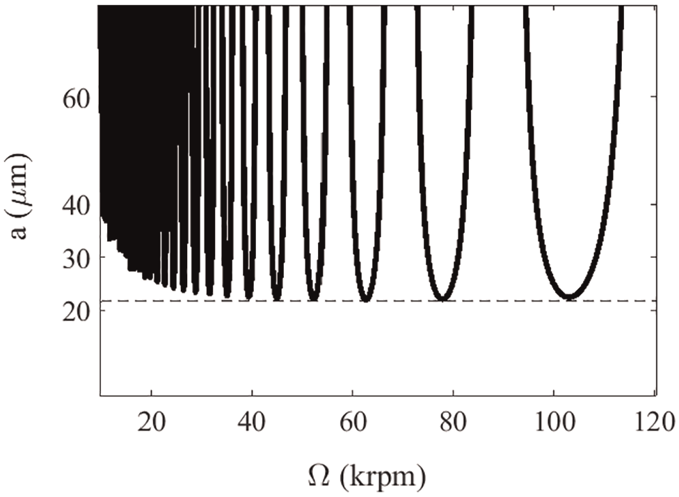
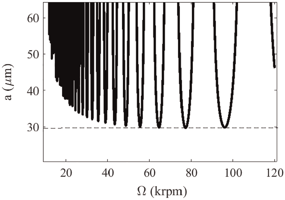
Figures 10 and 11 show the constructed SLDs of the tool with the unoptimized features in Table 1 and the optimized values in Table 7, respectively.
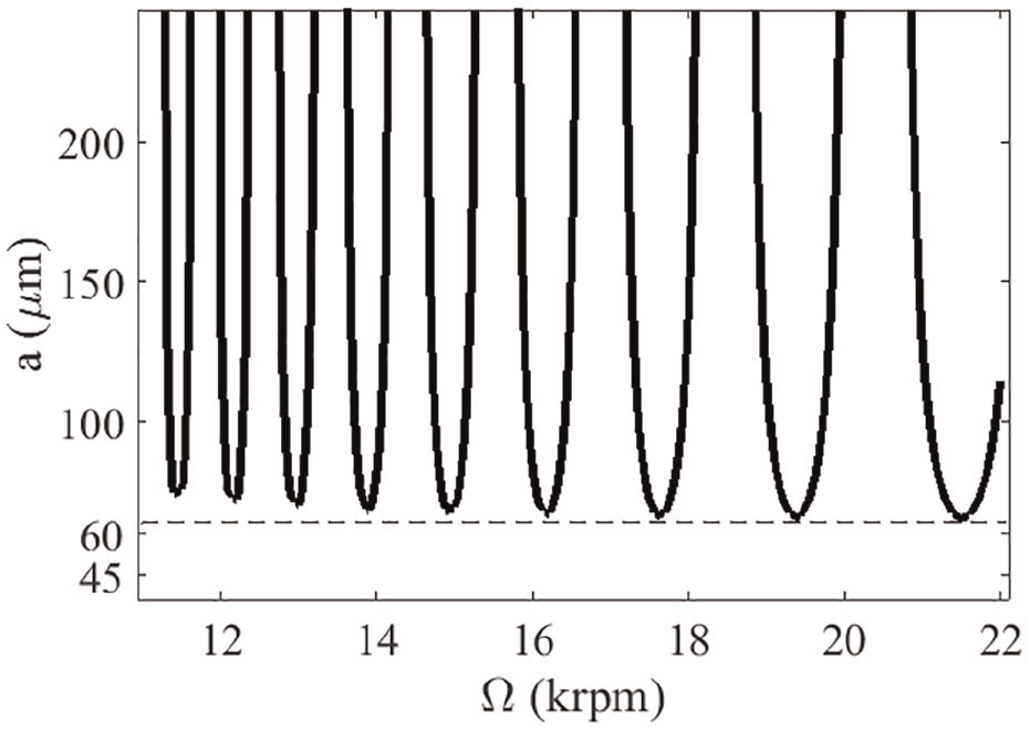
Stability lobe diagram based on unoptimized tool with the features presented in Table 1.
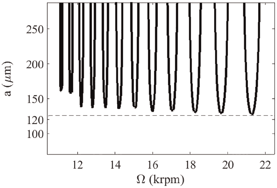
Stability lobe diagram based on optimized tool with the features presented in Table 7.
A remarkable result from these figures is that the optimum cutting depth for the optimized tool is
Optimization: example 2
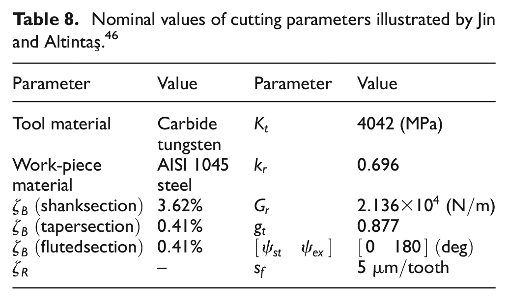
In this sub-section, another realistic example of optimization for a micro-milling process introduced by Jin and Altintaş 46 is presented. The nominal values of cutting parameters presented by Jin and Altintaş 46 for full immersion milling are tabulated in Table 8.
Nominal values of cutting parameters illustrated by Jin and Altintaş. 46
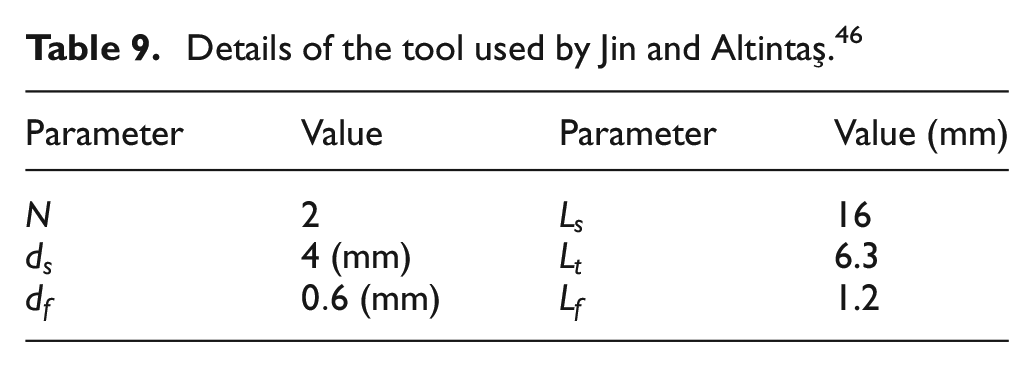
In addition, the details of the tool used by Jin and Altintaş 46 including number of teeth and tool geometry are presented in Table 9.
Details of the tool used by Jin and Altintaş. 46
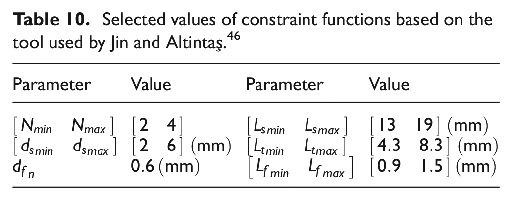
In current GA, various numbers of iterations are examined to get proper convergence to optimized value. To ensure the accuracy of the results, the values of constraint functions are selected in a range around realistic nominal values of Table 9, as illustrated in Table 10.
Selected values of constraint functions based on the tool used by Jin and Altintaş. 46
In addition, the value of
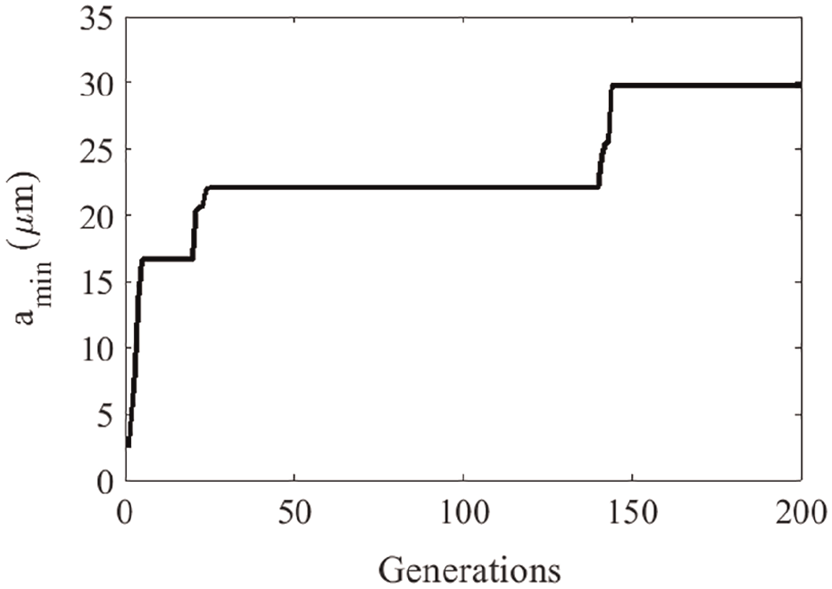
Variation of the objective function with number of generations based on the tool used by Jin and Altintaş. 46
As can be seen from Figure 12, the optimum value of cost function obtained from GA is
The values of variables in the optimum situation based on the tool used by Jin and Altintaş. 46
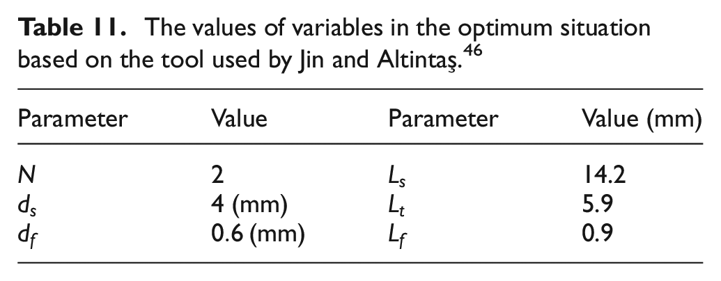
The constructed SLDs based on data before applying optimization in Table 9 and after that in Table 11 are shown in Figures 13 and 14, respectively.
An interesting result from these figures is that
Conclusion
To maximize the allowable cutting depth to chatter-free micro-milling process, an optimization procedure based on GAs has been presented in this article. For this reason, the tool has been modeled as a nonlinear 3D spinning cantilever Timoshenko beam based on strain gradient theory. To identify the system parameters, an optimization method has been presented to calculate the natural frequency, damping ratio, and material length scale of the cutting tool. The comparison between the experimental chatter test and predicted results shows the accuracy of presented model.
The procedure explained in this study has made an important improvement in micro-milling efficiency and designing of micro-milling tool. An optimization method using GA has been applied to micro-milling process with decision variables including number of teeth, shank diameter, diameter of fluted section, shank length, taper length, and length of fluted section. The analytical solution has been carried out by applying MSM and MMS on the DPDEs of the system to obtain the SLDs. The cost function of the optimization procedure has been defined as maximization of the minimal cutting depth on the border of SLD. Results show that the obtained cutting depth for the optimized tool is much more than the cutting depth for unoptimized tool. This optimization method may help the operators to order a specific design of micro-milling tool with optimal geometry for a special machining. In addition, machining operators can select a micro-milling tool that its geometry properties are near the optimized one from the accessible tools in the markets.
In summary, the main superiorities of this study are as follows:
The calculation of material length scale using system identification.
The optimization of a micro-milling tool geometry to find the maximum allowable cutting depth for chatter-free machining.
The analytical study of micro-milling process stability to determine the allowable cutting depth as the objective function of the tool design optimization.
Footnotes
Appendix 1
Declaration of conflicting interests
The author(s) declared no potential conflicts of interest with respect to the research, authorship, and/or publication of this article.
Funding
The author(s) received no financial support for the research, authorship, and/or publication of this article.