
Abstract
An accurate dynamic model for the computer numerical control machine tool feed system is of great significance to improve the machining accuracy. However, the accurate dynamic model of the feed system is difficult to be established because its dynamic characteristics not only depend on the performance of subsystems, such as mechanical, electrical, and control, but also on the interaction between them. In order to solve this problem, a modular modeling method based on a non-causal connection is proposed in this article, and the multi-domain seamless integrated model for the ball screw feed system is established. First, the feed system is decomposed by modularization, and the interface models in each domain are defined. Then all the subsystems are modeled strictly, and the nonlinear characteristics of each subsystem are analyzed. Finally, the multi-domain seamless integrated model of the ball screw feed system is established by the non-causal connection of subsystem models, and the experiment is carried out to validate the system model. The experimental results show that the multi-domain seamless integrated model of the ball screw feed system established in this article can accurately reflect the dynamic characteristics of the real physical system, and has high prediction accuracy for the dynamic following error. It is of great significance to further study the multi-domain coupling characteristics and compensation control methods of the machine tool system.
Introduction
Feed drive systems are used to position the machine tool components carrying the cutting tool and workpiece to the desired location. 1 They are one of the most important subsystems of machine tools because of their positioning accuracy and speed determine the quality and productivity of machine tools. 2 Ball screw feed systems are widely used in computer numerical control CNC machine tools for their high positioning accuracy, transmission efficiency, as well as long life. 3 Ball screw feed systems consist of several subsystems such as mechanical transmission part, motors, sensors, controllers and power electronics. 4 The motor is powered by amplifier electronics connected to a computer numerical control system, the workbench moves in a straight line through the ball screw, and the position command of the workbench is generated by the numerical control device.
The dynamic characteristics of the feed system have important influence on the control performance, processing accuracy and processing stability of machine tools. An accurate and reliable model of ball screw feed systems is essential to improve the control accuracy of machine tools. There have been much research on the modeling of the machine tool feed drive system. Farrage and Uchiyama 5 focused on the study of the friction occurred in the feed drive systems and established a nonlinear friction model based on Fourier series. Other friction models can be found in Karnopp, 6 Jeong et al., 7 and Johanastrom and Canudas-de-Wit, 8 such as stick-slip, static friction, and Stribeck effects. Thermal deformation is another important factor that can affect the tracking performance of the ball screw feed systems. It has attracted much attention of researchers and numerous articles have been published.9–11 Different modeling methods for mechanical parts of the machine tool feed system are put forward.2,12–15 By using the hybrid element method, Zhang et al. 2 established the mechanical part model of a high speed ball screw feed drive system. Ebrahimi and Whalley 12 established the mechanical part model of a single shaft feed drive system by causal connection method, and the stiffness of each transmission component is considered emphatically. Lumped-parameter models are often used to analyze the dynamic performance of the mechanical part of ball screw feed systems. In order to overcome the shortcomings of lumped-parameters models, the investigation of hybrid, distributed-lumped parameter modeling methods for ball screw feed drive systems was conducted in studies.13–15 Most studies mainly concentrated on the modeling of the mechanical part. The researches mentioned above have done a detailed study of the mechanical part of the feed drive systems and made significant contributions to improving the performance of the ball screw feed systems, but have not considered the coupling effect between different fields. In fact, the feed systems consist of multi-domain subsystems, such as the mechanical transmission subsystem, electrical subsystem, control subsystem, and so on. These subsystems belong to different disciplines and there is a complex coupling relationship among them. The performance of the feed drive system depends not only on the performance of the subsystems in each domain but also on the interaction between them. Therefore, a multi-domain integrated system model is essential to design high-performance ball screw feed systems.
Research on multi-domain integrated modeling of ball screw feed systems has been rare so far. Kim and Chung 4 proposed a system modeling method of the feed system, established each subsystem model, and emphatically analyzed the coupling effect of the mechanical subsystem and control subsystem. Some other integrated modeling methods for feed drive systems in machine tools can be found in Ding et al., 16 Zaeh and Baudisch, 17 Yang et al., 18 and Ansoategui and Campa. 19 The multi-domain coupling characteristics of feed system are taken into account and the multi-domain integrated model were established in these articles. However, the component-based causal connection modeling method is commonly used in the articles, the deficiencies are that the modeling efficiency is low, the model is complex and difficult to understand, and the model’s structure is far from the real system’s topological structure. Some attempts have been made to use the non-causal modeling method based on Modelica to establish the model of the feed system, but the model was not strictly in accordance with the actual system and the model was not validated by experiment.20,21
In view of the multi-domain coupling characteristics of feed drive systems and the shortcomings of the traditional modeling method, this article proposed the non-causal modeling method based on Modelica language to strictly model each subsystem of ball screw feed system. And then the seamless modeling of multi-domain integration of the feed drive system is realized by the connection of each subsystem. By comparing the experimental results and simulation results of the workbench displacement and the motor torque current, the model of the ball screw feed system is verified. And the experimental results show that the accuracy of the model is high.
The remainder of this article is organized as follows. Section 2 introduces the modular non-causal modeling method based on Modelica. Section 3 introduces the multi-domain integrated modeling process for the ball screw feed system. Section 4 introduces the experimental verification of the multi-domain integrated model. Section 5 summarizes the full text.
Multi-domain integrated modeling method
The ball screw feed system is usually composed of motors, controllers, drivers, mechanical transmission, and other components. It is a complex system involving multiple domains, such as mechanical, electrical, and control. These subsystems in different disciplines show the characteristics of tight coupling, and at the same time, they also show the characteristics that the continuous domain (such as mechanical subsystem) is mixed with the discrete domain (such as control subsystem). The ball screw feed system model closed to the real system is hard to be established by the traditional modeling method. In this article, a modular non-causal modeling method based on Modelica language is used to establish the multi-domain integrated model of the feed system in machine tools.
Modelica is an object-oriented physical system modeling language, which supports the modeling of a complex system based on component non-causal connection and the modeling of a continuous and discrete hybrid system. In Modelica, the interface of the component model is called the connector, and the coupling relationship between the component connectors is called the connection. The connection can be divided into causal connection and non-causal connection. Causal connection means the coupling relationship is causal while the non-causal connection means the coupling relationship is non-causal. The component model connection mechanism in Modelica is shown in Figure 1.
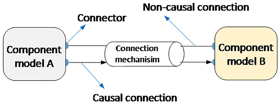
Component model connection mechanism.
The key to establish the multi-domain integrated model of the ball screw feed system is how to divide the system and define the connectors of component models in different domains. In this article, the ball screw feed system is divided into three main subsystems according to its real physical structure, which are control subsystem, electrical subsystem, and mechanical subsystem. Each subsystem can be further divided into several components. Then the connectors in each domain are defined and the component models are established based on an equation using the Modelica language. Finally the multi-domain integrated model of the feed system is established by connecting component models. The ball screw feed system studied in this is driven by a permanent magnet synchronous motor (PMSM). The result of the module division of the feed system is shown in Figure 2.
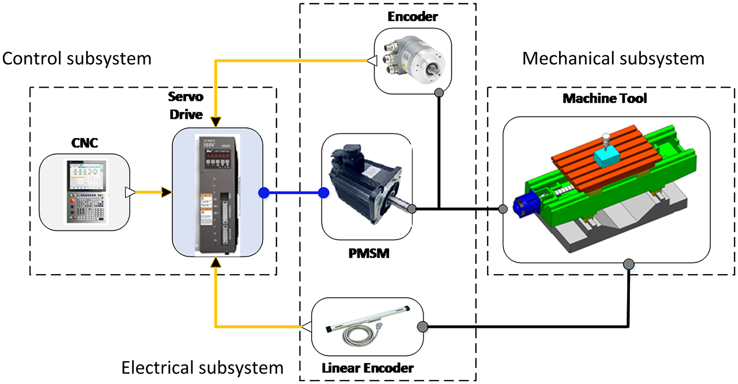
Module division of the feed drive system.
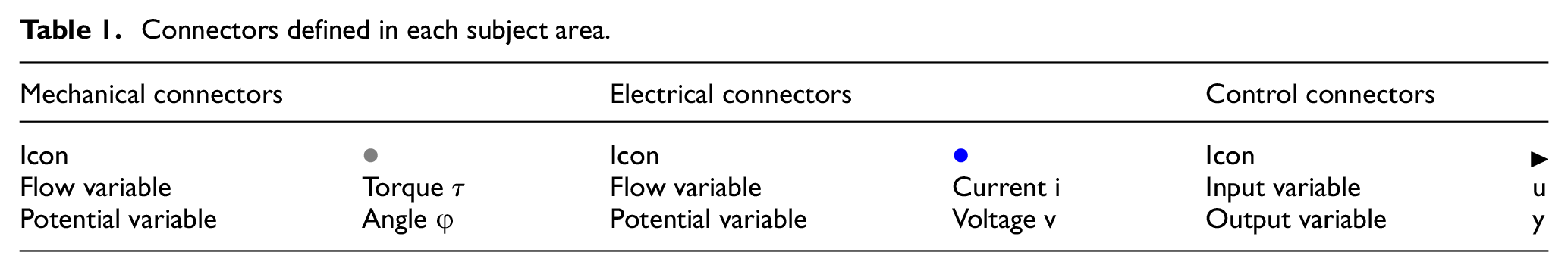
The connector in each domain should be defined so that each component model can be connected. In a non-causal connection, the connector in each domain usually contains two types of variables: flow variable and potential variable. When the connector is connected, it satisfies the generalized Kirchhoff theorem, that is, the sum of flow variables is zero and the potential variables are equal. In causal connection, the connector includes input variables and output variables. In this article, the connection in the mechanical and electrical fields is the non-causal connection, and the connection in the control field is the causal connection. The connectors defined are shown in Table 1:
Connectors defined in each subject area.
Multi-domain integrated modeling of the ball screw feed system
Modeling and analysis of the mechanical subsystem
The mechanical part of the ball screw feed system is usually composed of sub-components such as coupling, ball screw, supporting bearing at both ends, linear guide rail, screw nut, and worktable. When establishing the mechanical subsystem model, the mechanical connector interface is defined first, and then the component models are established based on the equation. The modeling schematic diagram is shown in Figure 3. The output torque of servo motors is represented as
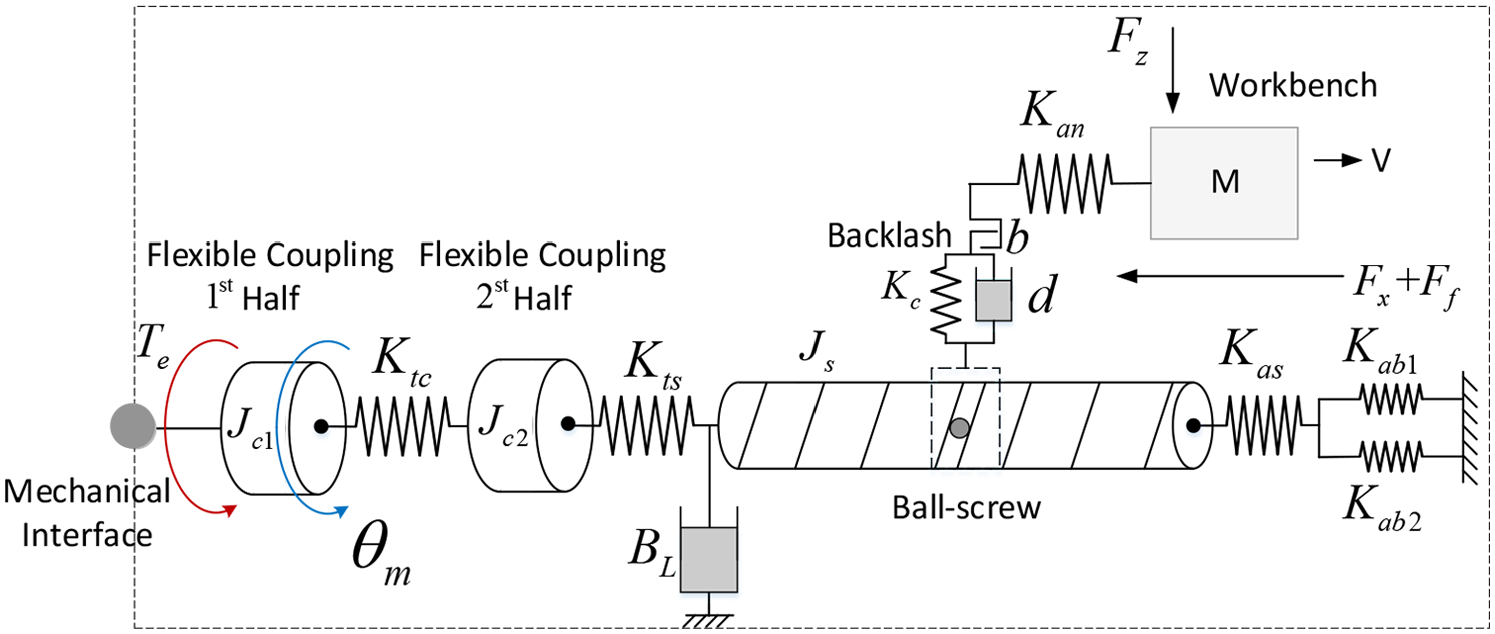
Illustration for the schematic diagram of the mechanical subsystem.
Considering the flexibility of each mechanical component, then


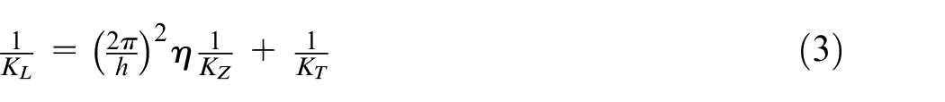
where
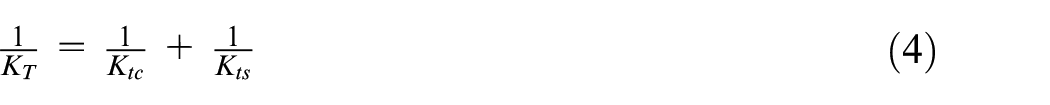
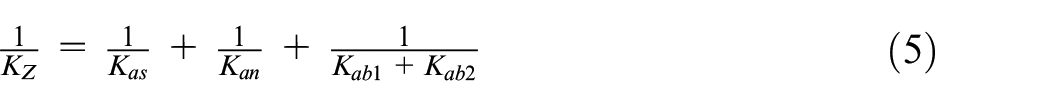
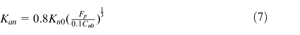
The axial stiffness of the lead screw varies with the movement of the worktable 22
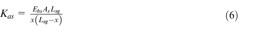
The axial stiffness of the nut
For the lead screw, the moment balance equation on the shaft is as follow:

There is a backlash between the ball screw and the nut. The backlash has nonlinear characteristics, which has a great influence on the positioning accuracy of the feed drive system. In this article, a nonlinear elastic method 23 is used to analyze the backlash model. The characteristics of the backlash are abstracted to a nonlinear spring. When the screw is in the gap zone, the spring stiffness is zero, and when the screw passes through the gap zone, the spring becomes stiff. The torque-angular displacement curve is shown in Figure 4.
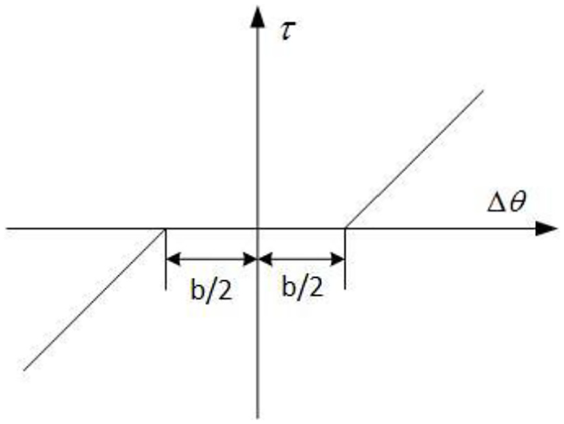
The nonlinearity of the backlash model.
Then the load torque on the screw shaft can be calculated as follow
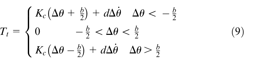
In equation (9),
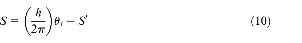
Where
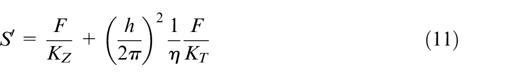
In equation (11), F is the driving force of the worktable, which is generated by the torque

For the worktable, according to Newton’s theorem, the force equilibrium equation is as follows

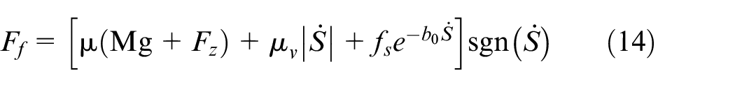
According to Stribeck model, the friction force can be calculated as follows:
As previously mentioned, Modelica is the modeling language based on the equation, so by synthesizing the above formulas, the dynamic model of the mechanical part of the ball screw feed system can be established. Then the connector for data exchange with other models is set up and the model is encapsulated. The encapsulated model of the mechanical part can be seen in Figure 9.
Analysis of the control subsystem
In the machine tool feed system studied in this article, the space vector control algorithm is used in control subsystem, which includes position control loop, speed control loop and current control loop. The input of the control subsystem is continuous signal and the output is discrete switching control signal. The input and output interface, and the block diagram of the control subsystem are shown in Figure 5. It can be seen from the Figure that after Clark and Park transformation, the input feedback three-phase current
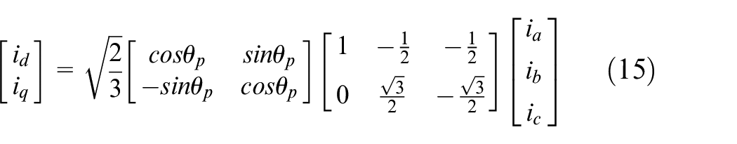
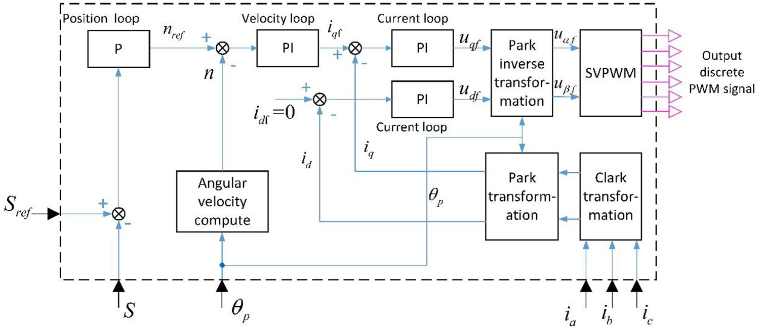
Illustration for the modeling of control subsystem.
The reference current
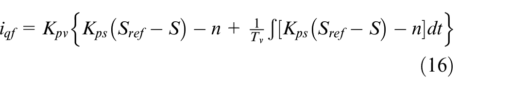
so,
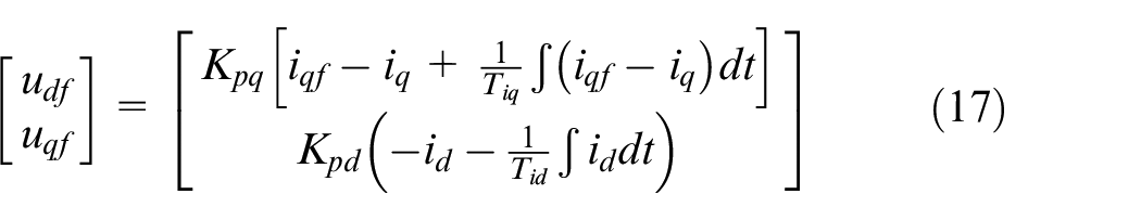
By inverse Park transformation, the
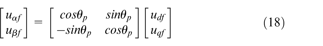
Then the
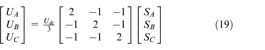
The motor is fed by PWM voltage source thyristor inverter, and the voltage modulation mode is space vector pulse width modulation (SVPWM). The control subsystem mainly is composed of the digital proportional integral (PI) controller, coordinate transformation module, and SVPWM module. The modular modeling method described above is applied to establish the control subsystem model. In fact, all the module models with input and output interfaces are established first according to its mathematical principle. Then by the connection of component models, the control subsystem model can be obtained. The encapsulated model of the control subsystem can be seen in Figure 9.
Modeling of the electrical subsystem
In the ball screw feed system studied in this article, the driving motor is fed by PWM voltage source thyristor inverter. The electrical subsystem is composed of the inverter and the PMSM, as showed in Figure 6.
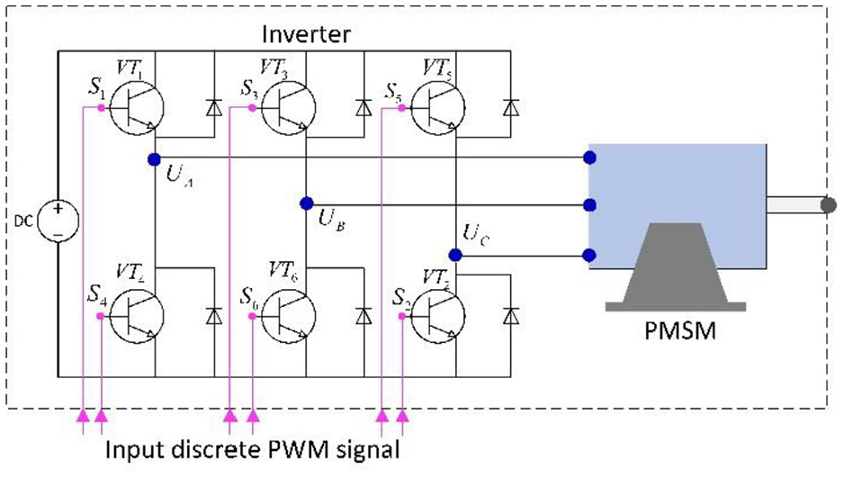
Illustration for the modeling of electrical subsystem.
In Figure 6, VT1∼ VT6 are power switch tubes, and the on-off of each switch is controlled by the drive signal S1∼S6.
Similarly, the basic component models such as power switch transistor, diode and electrical connectors are established first, and then the inverter model is established by connecting the component models according to the topology circuit structure of the inverter.
The inverter model is connected with the PMSM model by the electrical connectors. In order to simplify the analysis of PMSM model, the following assumptions should be made before establishing the mathematical model:
The conductivity of permanent magnet material is zero;
There is no damping winding on the rotor;
Stator winding current produces only sine distribution of magnetic potential in the air gap, ignoring the high-order harmonic of magnetic fi; and
During the steady-state operation, the waveform of the induction electromotive force in phase winding is sinusoidal.
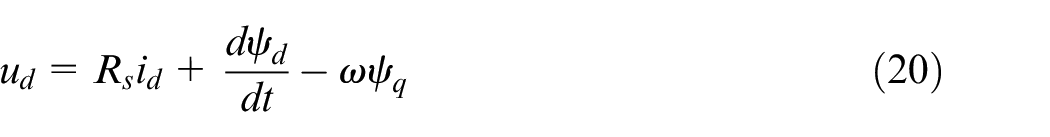
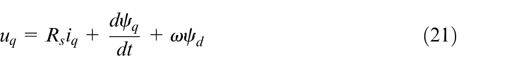
The physical quantities of AC motor windings, such as voltage, current and flux, vary with time, and time phasors are often used to represent them. However, they can also be defined as spatial vectors if considering the space position of the windings. The synthetic vector formed by the physical quantities in three-phase windings is the synthetic space vector of these physical quantities. The symmetrical three-phase current, voltage and flux linkage in three-phase symmetrical stator windings of permanent magnet synchronous motor can be regarded as space vector. Three-phase voltage
The voltage equation of d and q axis is shown below
The flux linkage equations of d and q axes are as follows


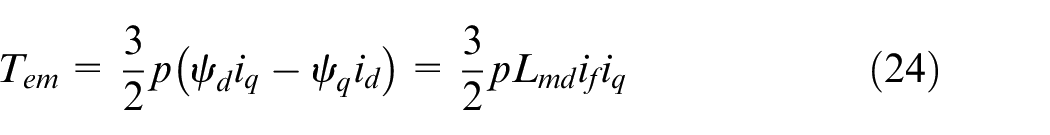
The electromagnetic moment equation acting on the motor shaft is as follows:
Based on the above PMSM mathematical model, the equivalent circuit of PMSM in d and q axis coordinates can be obtained, as shown in Figure 7.
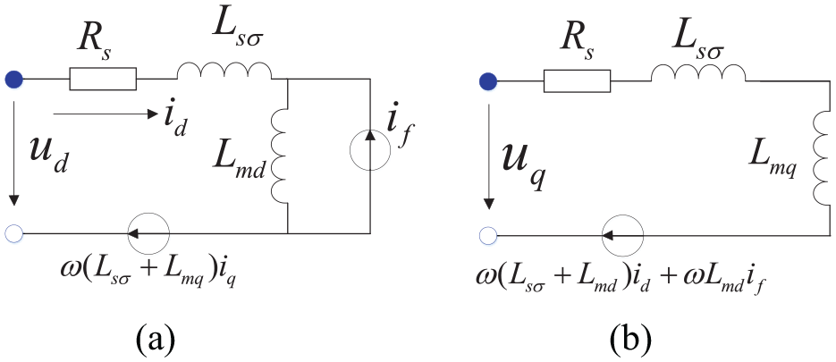
Equivalent circuit of PMSM. (a) Equivalent circuit of d axis. (b) Equivalent circuit of q axis.
Based on the analysis and the equivalent circuit mentioned above, and considering the loss models of copper, iron and friction, a permanent magnet synchronous motor model is established. The inverter model and PMSM model constitute the electrical subsystem model.
Multi-domain integrated system model
Each subsystem model is developed by connecting the basic component models. Similarly, the ball screw feed system model is established by connecting the above subsystem models. The transformer models play a key role in connecting each subsystem model from different domains. Because of the existence of transformer models, the three subsystem models can be integrated seamlessly. And at the same time, the mathematical equation of the whole system is generated, as show in the Figure 8. The input and output among different domains can also be seen in Figure 8.
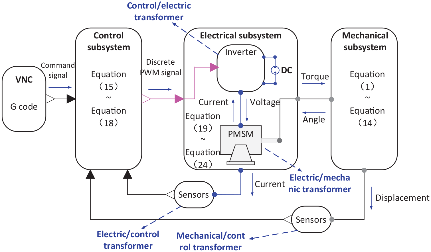
Illustration for the modeling of the whole system.
Finally, the whole system model is established. It is multi-domain coupling and continuous and discrete-event mixed system model, which can better express the characteristics of the real system. The whole system model structure is shown in Figure 9. The model also includes VNC module model and sensor models. VNC module can load G code file and output the position command signal of the worktable. The sensor models can measure the angular displacement of the motor and the displacement data of the workbench.
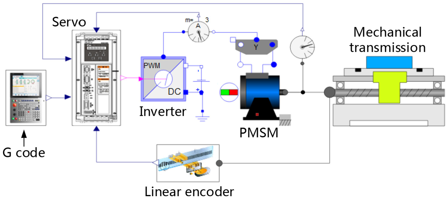
The multi-domain integrated system model of the ball screw feed system.
System responses from simulation and measured results
Experiment and simulation
In order to verify the accuracy of the multi-domain integrated system model, a single-axis feed system test platform is set up, as shown in Figure 10.
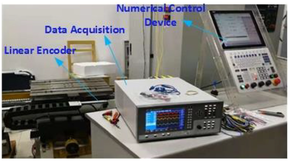
Experimental test platform for single axis ball screw feed system.
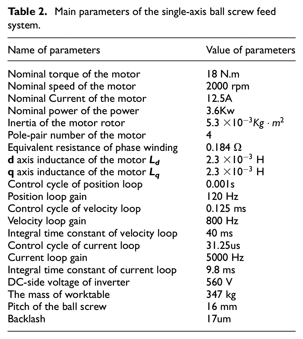
The main parameters of the feed system in the Figure 10 are shown in the Table 2:
Main parameters of the single-axis ball screw feed system.
Based on the friction model mentioned above, the friction coefficient is identified by the experimental data at different velocities. The friction model equation is as follows

Import these known parameters and the parameters identified by the experimental data into the multi-domain integrated model of the ball screw feed system. The step and a sinusoidal position command signal are given to the control system, in turn, then the simulation results can be obtained. The given command signal is shown in Figure 11.
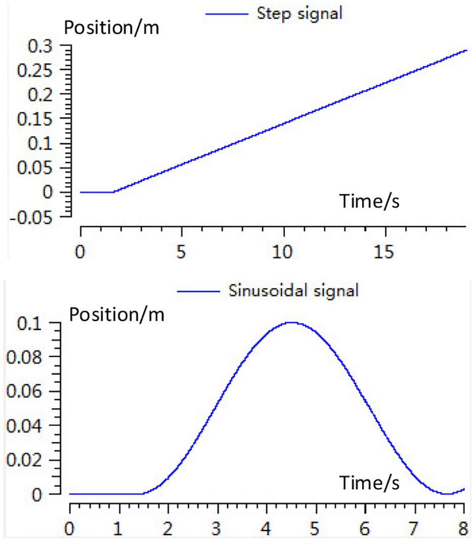
The step and sinusoidal reference position command signal.
The same position command signal is input to the real system and the experiment data of the worktable’s displacement, velocity, acceleration, and torque current is measured. The simulation results are compared with the experimental results. The comparison results are shown in Figure 12. Figure 12(a) shows the deviation between the following error predicted by the model and that measured by the experiment. Figure 12(b)–(d) show the comparison between the measured results of the velocity, acceleration of the worktable and torque current, and the corresponding simulation results.
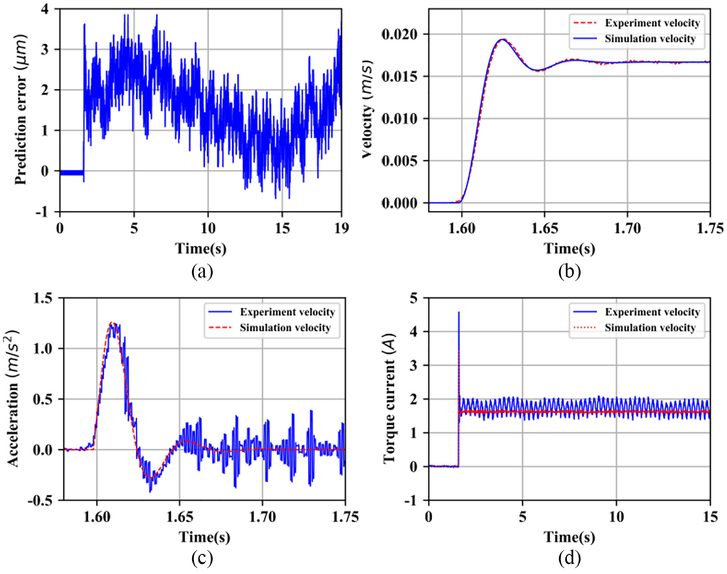
(a) Deviation between following error predicted by the model and that measured by experiment and (b) comparison between simulation results and experiment results of worktable velocity and (c) comparison between simulation results and experiment results of worktable acceleration and (d) comparison between simulation results and experiment results of torque current.
Figure 13(a) shows the comparison of simulation results, experiment results and the command signal of the worktable of displacement. The curve in Figure 13(b) shows the deviation between the following-error predicted by the model and that measured by the experiment.
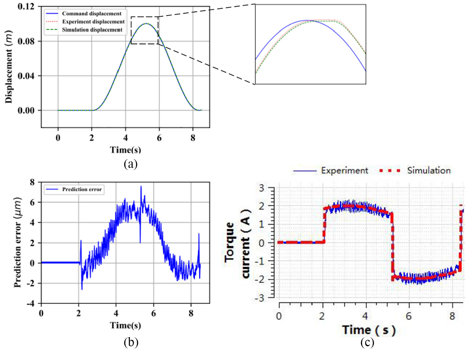
(a) Comparison between simulation results and experimental data of worktable displacement and (b) prediction error under sinusoidal wave command displacement and (c) Comparison between simulation results and experimental results of torque current.
Figure 13(c) shows the comparison between the measured torque current and the simulated torque current.
In order to verify the veracity and stability of the model in prediction of the worktable’s displacement, the sinusoidal position command signal with different frequencies was given to the ball screw feed system. Four experiments were carried out and the peak velocity of the worktable was set to 2000 mm/min, 4000 mm/min, 5000 mm/min, and 6000 mm/min respectively. The differences between the experimental results and the simulation results were analyzed. The deviation between tracking-error predicted by the model and that measured by the experiment is shown in Figure 14. The comparison of torque current calculated by the model and that measured by the experiment under different peak velocity are shown in Figure 15.
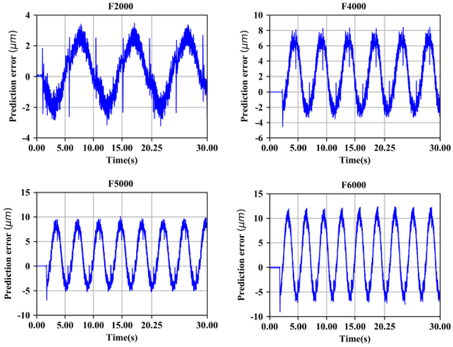
The deviation between the tracking error predicted by the model and that measured by the experiment under different speed.
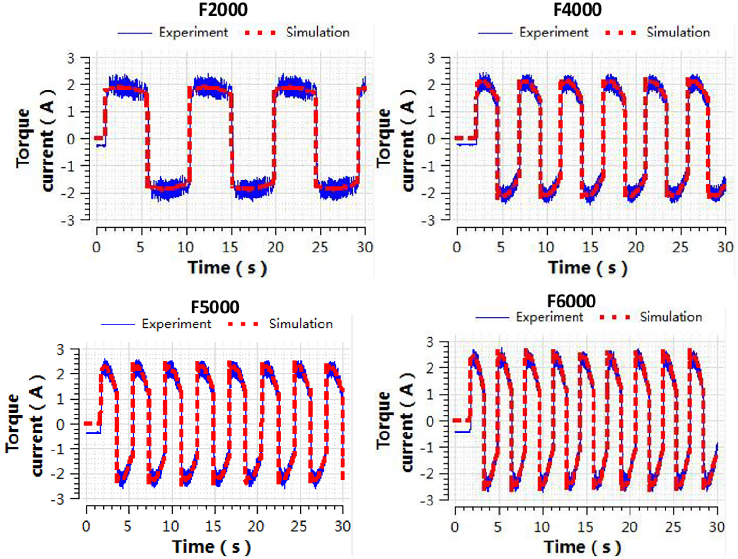
Comparison of torque current calculated by the model and measured by the experiment.
As can be seen from Figures 14 and 15, the deviation between tracking-error predicted by the model and that measured by the experiment increases with the increase of feed speed. Though the peak feed speed varies, the simulation results of torque current are consistent with that the measured, and the two curves are basically coincident.
At different peak feed speeds, in order to evaluate the difference between the simulated and experiment results quantitatively, the upper bound of error, lower bound of error, and relative error (RE), refer to the ratio of absolute error to measured true value, expressed as percentage) were evaluated, as shown in Table 3.
The maximum deviation of tracking error between the experimental results and the simulation results.
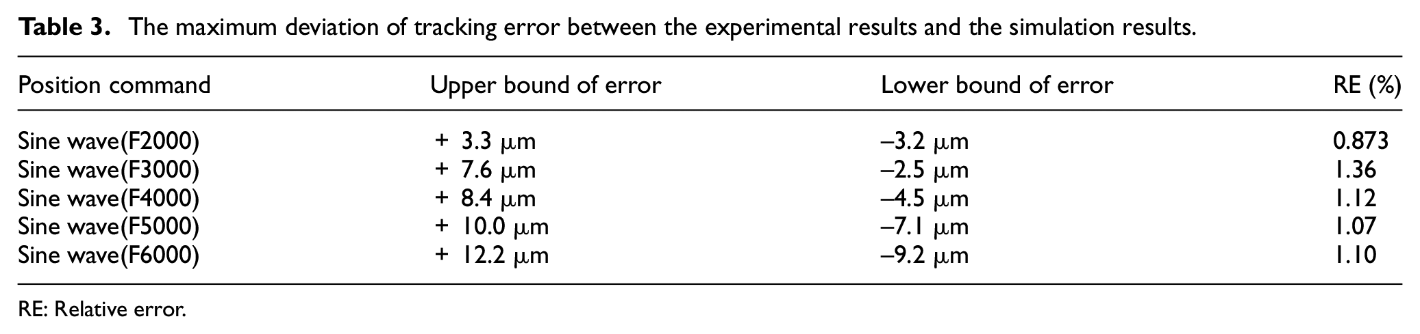
RE: Relative error.
Analysis and discussion
Most researches on the modeling of the ball screw feed system focus on the modeling and simulation of a single field such as mechanical transmission. The traditional single domain modeling method almost ignores the coupling effect among the subsystems in different domains.
For the integrated modeling of the ball screw feed system, the traditional modeling method is the causal connection based on component models. This is a modeling method based on signal flow, which requires manual derivation and transformation of complex mathematical equations. The method is suitable for the modeling of the control system. However, using this signal-oriented approach for physical systems such as the ball screw feed system yields complicated structures that are difficult to understand. In this article, the feed system model is established by using the modeling method of non-causal connection based on component models. This is a modeling method based on energy flow, which can avoid the derivation of complex equation system, so as to reduce the difficulty of modeling.
The modeling method proposed in this article is different from the traditional modeling method. The comparison between the two is shown in Figure 16.
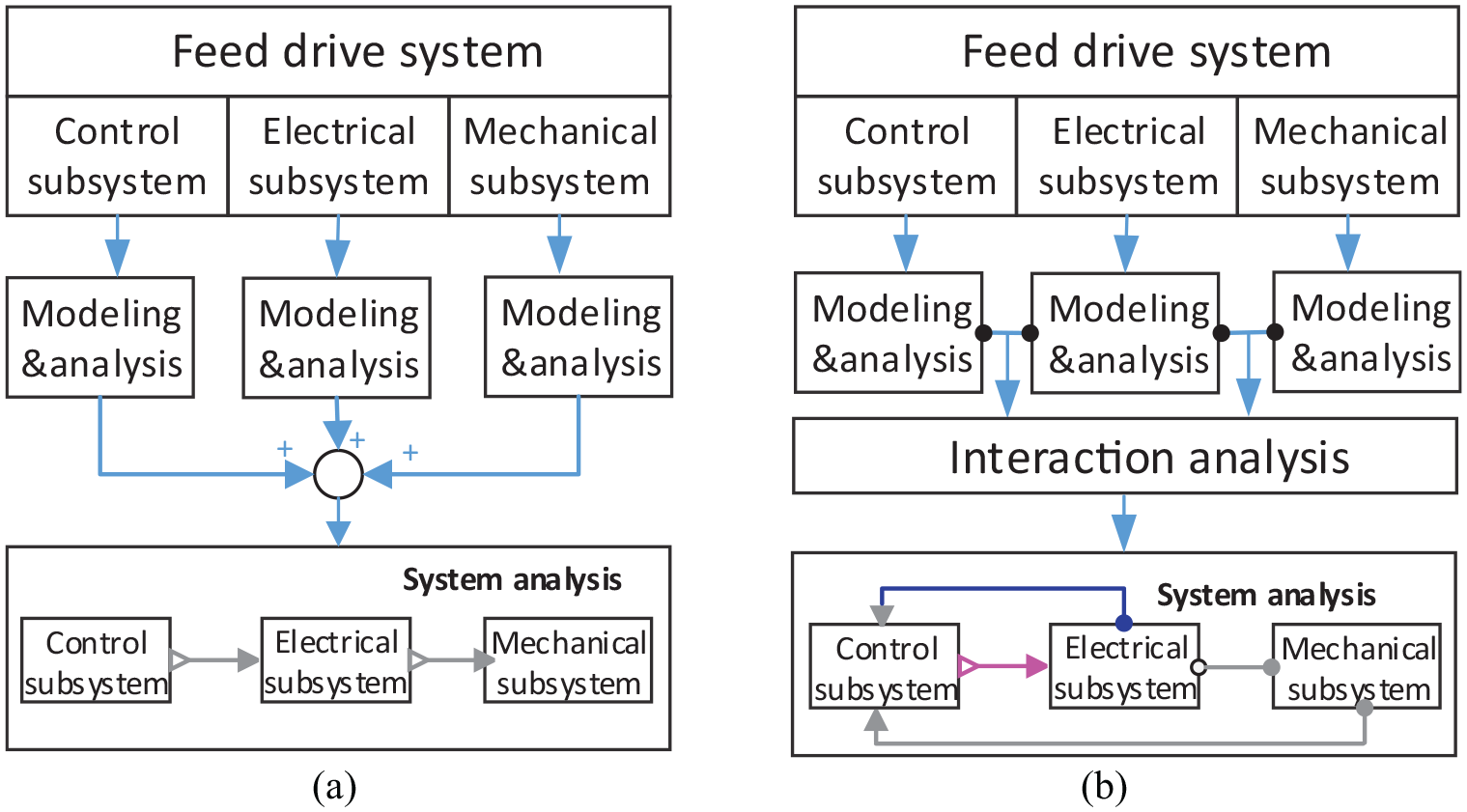
Traditional modeling method vs multi-domain integrated modeling method. (a) Traditional modeling method and (b) multi-domain modeling method.
The experiment results show the superiority of multi-domain integrated modeling method. From the comparison of simulation results and experimental data, it can be found the integrated system model established in this article is accurate. Under the step position command signal, in Figure 12, the maximum deviation between the predicted and measured is about 3.8um, which is about 1.79% of the maximum measured tracking error. And the simulation results of velocity, acceleration, and torque current are basically coincident with the corresponding measured results. Under the sinusoidal position command signal, in Figure 13, the maximum deviation between the prediction value of the tracking-error and the measured value is about 7.5um, which is about 1.34% of the maximum measured value of follow-up error. It can be seen from Figure 14 that even under different peak feed speeds, the system model also has high prediction accuracy. From the Table 3, it is found that although the deviation between tracking-error predicted by the model and that measured by the experiment increases slowly with the increase of the peak feed speed, the percentage of the deviation to the measured value of the tracking error does not change much.
Compared with the feed system model established by using the traditional modeling method, the model developed in this article is closer to the real feed system and can reflect the response characteristics of the real system better. For example, in Guo et al., 27 a hybrid mechanical model of the ball screw feed system is established, the maximum position prediction error is more than 20 μm. However, the maximum position prediction error of the ball screw feed system model developed in this article is less than 12.2 μm.
Conclusion
A multi-domain seamless integrated model of ball screw feed system, including the numerical control device, servo control system, servo motor, and mechanical transmission system, is established in this article. The system model is verified by experiment results and the verification results show that the deviation between the dynamic tracking-error prediction results and the experiment results is relatively small at different feed speeds. The simulation results of torque current are in good agreement with the experiment results. The model validation and analysis results show that the multi-domain integrated model of the ball screw feed system can accurately reflect the dynamic response characteristics of the real system and accurately predict the dynamic tracking-error. The system model established in this article is closer to the real system and has higher accuracy. This lays a theoretical foundation for further study of the multi-domain coupling characteristics and the dynamic tracking-error compensation control of the ball screw feed system.
Footnotes
Appendix 1
Declaration of conflicting interests
The author(s) declared no potential conflicts of interest with respect to the research, authorship, and/or publication of this article.
Funding
The author(s) received no financial support for the research, authorship, and/or publication of this article.