
Abstract
In the traditional sculpture surface machining process, the G01 code is still the mainstream trajectory. Furthermore, real-time feedrate scheduling and corner smooth algorithm in controller constitute the mainstream method to improve the machining process of short line G01 code in sculpture surface machining. However, the G01 code’s discontinuity and the limits of real-time calculation capacity hinder the use of high-speed machine tools and the accuracy of the machined part. In this article, a new method for sculpture surface machining that considers the advantages and disadvantages of both the computer-aided manufacturing software and the real-time controller is presented to promote the use of a continuous curve tool path. The method mainly transfers the computing-intensive feedrate scheduling and trajectory optimization algorithm in the real-time controller to the computer-aided manufacturing software. Furthermore, the computer-aided manufacturing software generates the machining data, which contain the geometry and feedrate information of the machining process. Finally, the real-time interpolator and the mathematical form of computer-aided manufacturing–generated data are designed simultaneously. In the method, the real-time controller can be designed as simple as possible to release more computing resources to the other real-time intelligent modules. The powerful computational capacity of the software guarantees the optimality of the machining process.
Keywords
Introduction
For the sculpture surface machining process, the G01 code trajectory combined with real-time linear interpolation is the main stream machining method. However, the discontinuity of the G01 code impedes the accuracy and smoothness of the machining process.1,2 A straightforward, curve tool path can be used to solve these problems owing to its high-order continuity.3,4 However, the curve tool path in freeform surface machining is still not widely used, although the curve tool path generating method and curve interpolation have been studied for many years.5–7 According to the authors, there are three reasons for this lack of utilization.
First, tool path planning for a freeform surface requires a considerable amount of numerical calculation, and it is difficult to generate the curve tool path directly. 8 For surfaces such as sphere and conicoid, the tool path in the parameter curve form can be generated under certain rules. To the best of authors’ knowledge, Schützer et al. 9 calculated B-spline tool paths using only the properties of the spline surfaces, which is opposite to converting a non-uniform rational B-spline (NURBS) based computer-aided design (CAD) model into a tessellated computer-aided manufacturing (CAM) model. Obviously, the method is overly complex and can only be used to generate tool paths under simple rules. Nowadays, tool path planning for a freeform surface is another important topic of research.10–12 However, generating a spline tool path under those rules will be more difficult. Therefore, a numerical calculation will still be used in tool path planning, and a set of discrete points will still be the main format of the tool path planning results. In CNC (computerized numerical control) real-time controller, many functions like cutter compensation are limited in real-time curve interpolation mode which also impedes the application of curve tool path.
At the same time, many commercial CAM software products transform the trajectory planning results (a large number of discrete points) into the G01 code directly. Nowadays, in CNC, linear interpolation is used to receive the G01 code. Corner rounding and the feedrate scheduling algorithm for linear interpolation are designed to increase the smoothness of freeform machining process such as those in Yang and Yuen 13 and Sencer et al. 14 Few years ago, the interpolation period was 1 ms. Recently, although the real-time algorithm has become more and more complex, the interpolation period can be 0.5 ms for the development of chips. For the number of blocks in the look-ahead function, taking FANUC as an example, the largest number of blocks in the look-ahead has become 1000 blocks for FANUC Series 30i-B from 180 blocks for FANUC Series 16i in their artificial intelligence (AI) nano contour control mode. At the same time, the commercial CNCs also provide some parameters (such as RADMAX, RMAX, TOL, and SM) to adjust these algorithm according to whether the operator likes higher speed or higher smooth. Some of these algorithms are in real time, some are not. But the calculation time is limited as the CNCs cannot let the operator wait too long. Therefore, the optimality and accuracy are compromised.
Next, for the various types of freeform surfaces, it is difficult to represent the trajectory planning results as a single curve using a simple fitting method. Although using a spline function to represent discrete points is a classical fitting problem, 15 it is still difficult to balance the number of the function parameters and the fitting accuracy. At the same time, even for a part, different surfaces or different machining processes also lead to many types of trajectories. Although the fitting accuracy can be guaranteed by classifying the original data points according to their features, 16 those features are difficult to obtain properly or be used universally. Lin et al. 17 propose a segmentation algorithm based on the angles and lengths, and an error-bounded constrained curve fitting algorithm is implemented to fit each segment of points into a curve.
Finally, the real-time calculating capacity of a CNC controller limits the interpolation accuracy 18 and the feedrate scheduling of a spline tool path. 19 For most curve tool paths, there is no analytical relationship between the arc length and the parameter, 20 and a precise arc length always needs an iterative calculation, which is unsuitable in real-time calculation. Therefore, numerous articles propose various methods to address the interpolation accuracy problem in spline interpolation. One approach is to increase the real-time arc length estimation accuracy 18 or provide a fitted arc length and parameter relation. 21 In another approach, an arc length parametrized tool path for CNC machining is also proposed, such as that put forward by Farouki,22,23 who presents Pythagorean–hodograph (PH) spline paths whose arc length is just a piecewise polynomial. Chen and Khan 24 propose an approach to generate arc length parameterized B-spline tool paths with high accuracy to address the disparity between the arc displacement and the spline parameter.
Currently, modeling and optimizing the machining process before physical trials have become the main trend in the manufacturing field.25–27 At the same time, the real-time calculating capacity becomes more precious as more and more intelligent modules are embedded in the real-time controller to tackle some stochastic and uncertainty events. Therefore, in my opinion, the certainty event, like tool path smoothing and feedrate scheduling in traditional CNC controller, would be better to be transferred to the offline CAM software. In this study, to increase the sculpture surface machining accuracy and alleviate the real-time calculation burden, a machine tool movement control method combining the benefit of the CAM software and real-time interpolator is proposed. The method uses the powerful calculation of software to improve the practicality of the spline tool path in sculpture surface machining, thus improving its machining accuracy and efficiency. The comparison between the traditional sculpture surface CNC machining process with the proposed machining process is depicted in Figure 1.
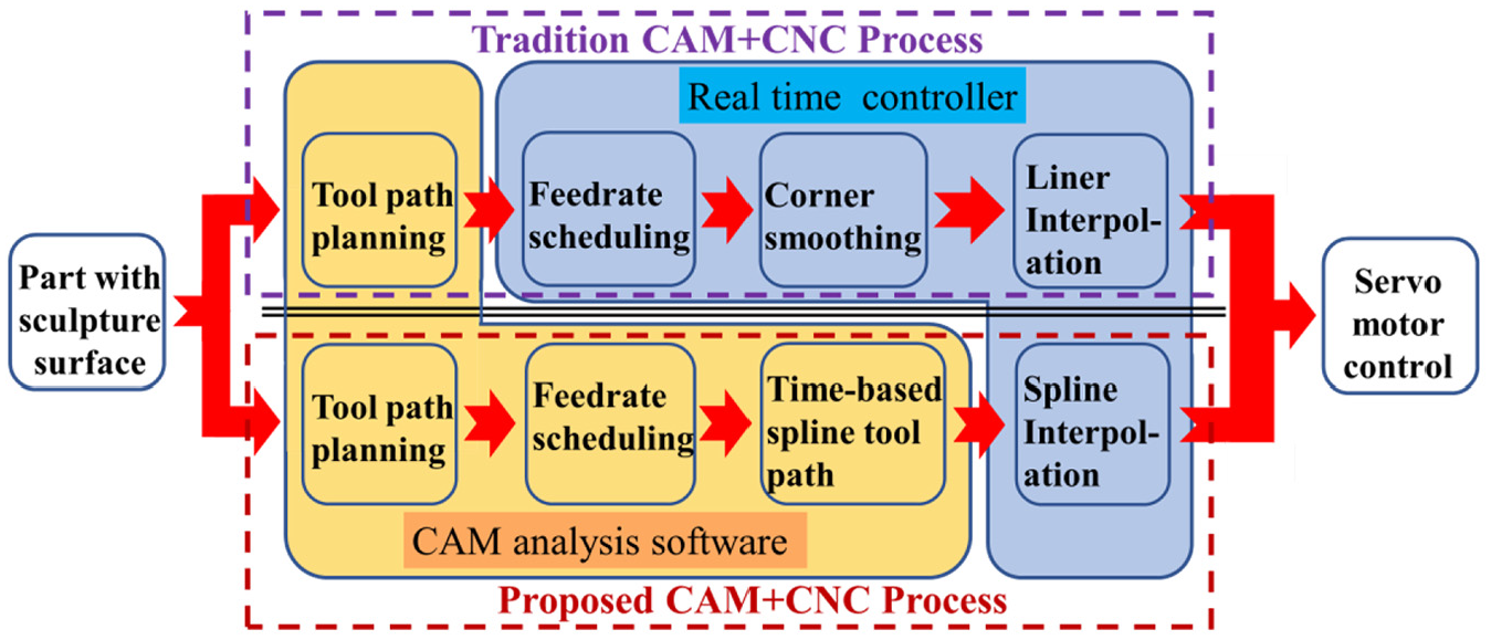
Comparison of the CAM + CNC sculpture surface machining processes.
The tool path for sculpture surface machining is planned by the numerical method, and the results are always a larger number of discrete points. Traditionally, these discrete points are set as G01 code and sent to the linear interpolation directly to control the movement of the machine. In the proposed method, the whole G01 codes for a part generated by CAM are set as original geometry data and are fitted by a spline curve first. Given the complexity of the discrete tool path, it is difficult to fit the data directly. Therefore, the original G01 code tool path needs to be pretreated to improve the fitting process.
Then, the cubic B-spline is chosen to fit the original G01 data. Its continuity is suitable for tool path. At the same time, the locality of the B-spline is beneficial to the varied curvature of the tool path. However, it is difficult to obtain the knot vector of B-spline properly. In this work, the B-spline knot vector is distributed by the given accuracy and curvature of the original data.
After the spline tool path is obtained, the whole machining process can be planned by the feedrate scheduling method according to the dynamic ability of machine tools and the requirements of the machining processing technique. Then, the axis position at each moment which contains the geometry and instant feedrate information can be obtained.
Finally, to alleviate the real-time calculating burden, the time-based curve tool path is generated from the feedrate scheduling results, and the corresponding time-based real-time interpolator is also designed. Compared with other spline interpolation methods, the real-time calculation of the time-based interpolator is much less as it does not need the real-time feedrate scheduling and arc length calculation. For a motion servo control system, the dynamic module has great influence on output accuracy, and this article focuses on generating smoother signal for the servo axis motor by fitting the discrete line tool path and feedrate scheduling. Combined with the smoother signal, the real-time controller should also be designed and adjusted to reduce dynamic errors and suppress the influence of the uncertainty noise.
Converting the G01 code to spline curve
For a freeform part, its tool path is always generated from the CAM software and the result is a large number of discrete points. As we all know, discrete points are unsuitable for high-speed freeform machining owing to their discontinuity. In this article, a cubic B-spline is proposed to represent the whole tool path. However, various types of G01 code need to be preprocessed to improve the fitting process.
Preprocess of the G01 code
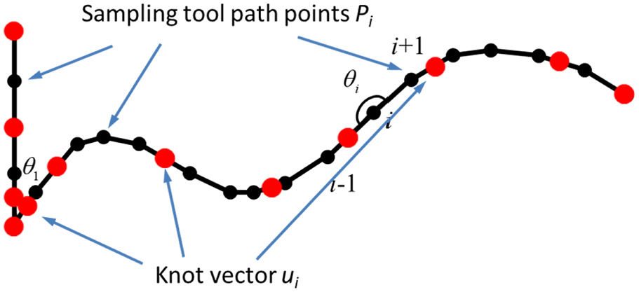
First, the original G01 code should be divided in some extreme curvature points. Compared with other complex dividing methods, this method just uses the angle of the adjacent tool path vector. The angle in the tool path point i is
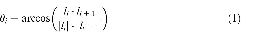
where
As shown in Figure 2, when the angle
G01 tool path points and their angles.
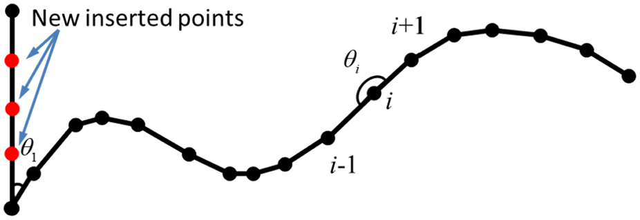
Sketch map of inserting process.
The threshold of the longer length G01 tool path can be chosen as the average length
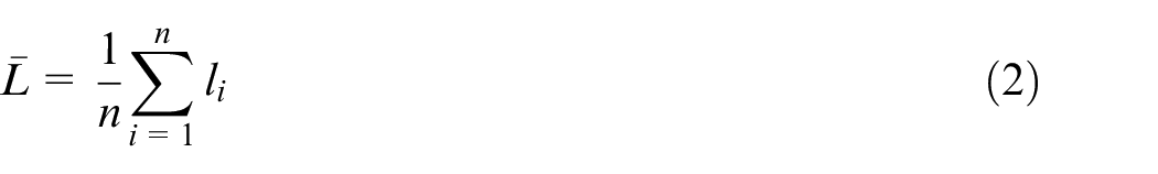
where
As the fitted B-spline is a parametric curve, each segment of G01 code needs to be parameterized. In this work, the chord length sum between the point and the start point is chosen as the parameter of the point. Thus, the parameters are
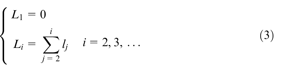
where
Cubic B-spline fitting process
Because the locality of the B-spline, it is suitable for the fitting of a whole tool path considering the tool path’s curvature diversity. However, the local characteristic of the B-spline is determined by the distribution of its knot vector. Therefore, how to distribute the knot vector according to the curvature of the G01 code is the key to satisfy the requirements of the fitting process.
In the proposed method, the knot vector is distributed according to the curvature of the G01 code. In the extreme curvature area, more knots would be distributed to meet the fitting accuracy requirements and also to separate the area from the nearby smooth region.
Distributing the knot vector of the B-spline
Assuming that the relationship to be fitted is y = f(x), then the Taylor expansion of the f(x) is
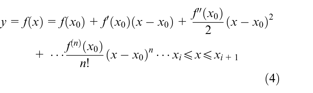
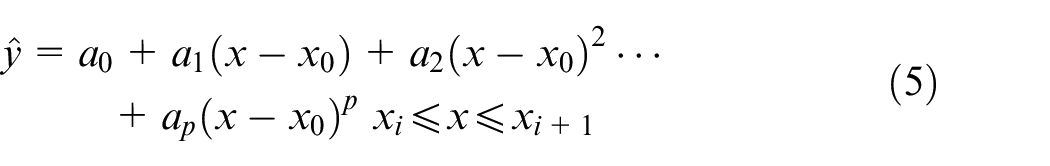
In most cases, the relationship is unknown but sampling points (xi, yi) can be provided. If the pth degree polynomial is used to approximate the relation y = f(x), the fitted function is
Then, the fitting error is

As the tool path is always continuous, the parameters a0, a1, a2, …ap of the fitted pth degree polynomial are considered to be near the coefficients of Taylor expansion. Then the fitting error can be simplified as
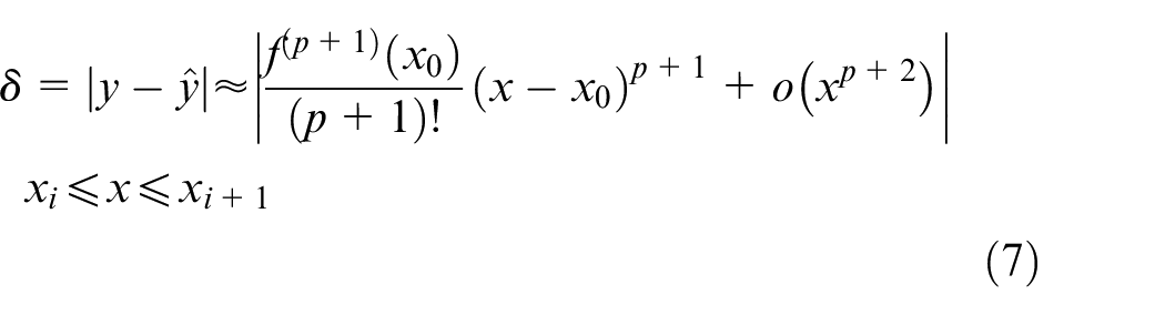
If the higher order remainder is eliminated and the
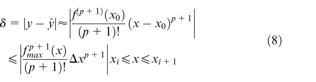
where
For the B-spline
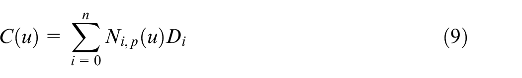
where Di represents the control points, and Ni,p(u) denotes the pth degree B-spline basis functions formed by the knot vector. Its knot vector is defined as

To guarantee that the first and last control points are the curve’s start and end points, the start and end of the knot vector are p + 1 multiples for open curves.
According to the definition of the B-spline, the pth degree B-spline is a pth degree piecewise polynomial. In each knot interval, such as
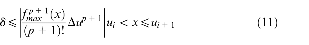
where
In the proposed method, the G01 tool path is to be fitted by the cubic B-spline. According to equation (11), the cubic B-spline fitting error in each interval
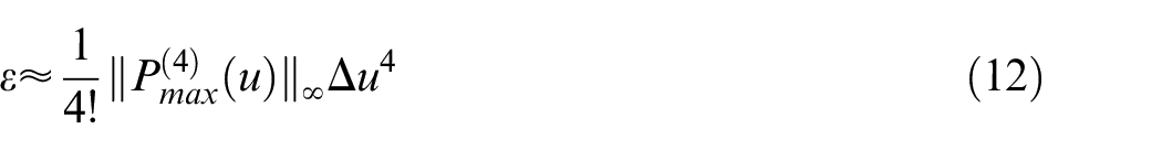
where
Step 1. The parameterized G01 tool path points series
Step 2. The first knot point is, u0 = L0, i = 1, j = 0;
Step 3.
Step 4. According to equation (12), the estimated fitting error
Step 5. If
Step 6. Go to step 3;
Step 7.
In step 4, the predicted error is calculated by equation (12), where
Finally, the multiples of the first and last knot points are increased to four. Then the predicted knot vector
Calculating the control points
For the B-spline fitting process, the control points can be easily obtained by the least squares (LS) method after the knot vector is determined. 15 However, during the knot vector determining process, in some knot intervals, there are probably no original tool path sampling points, as shown in Figure 4. As the B-spline is piecewise polynomial, during the use of the LS method to estimate the control points, if there are less original sampling points in some knot intervals, the LS equation becomes an unsolvable equation in that interval. Thus, the number of sampling points in each node interval needs to be verified before optimizing the control points, and the original data in that interval should be densified by just inserting the new data points linearly.
Sketch map of distribution of the knot vector.
Generating axis position in each moment by feedrate scheduling
After converting the G01 code to the spline tool path, a time-optimal control algorithm is used to schedule the machining process. Compared with the spline feedrate scheduling process in a real-time controller, the feedrate scheduling in the CAM software can obviously decrease the machining time and increase the machining smoothness. Besides, the increased amount of computation in the software is insignificant when compared with the tool path planning and analysis process in CAM.
During feedrate scheduling for freeform surfacing machining, the machining process and the kinematic ability of the machining equipment limit the machining feedrate and acceleration, indirectly influencing the machining time. Therefore, the feedrate schedule for a freeform surface is a constrained time optimal control problem. The mathematical model of the feedrate schedule is
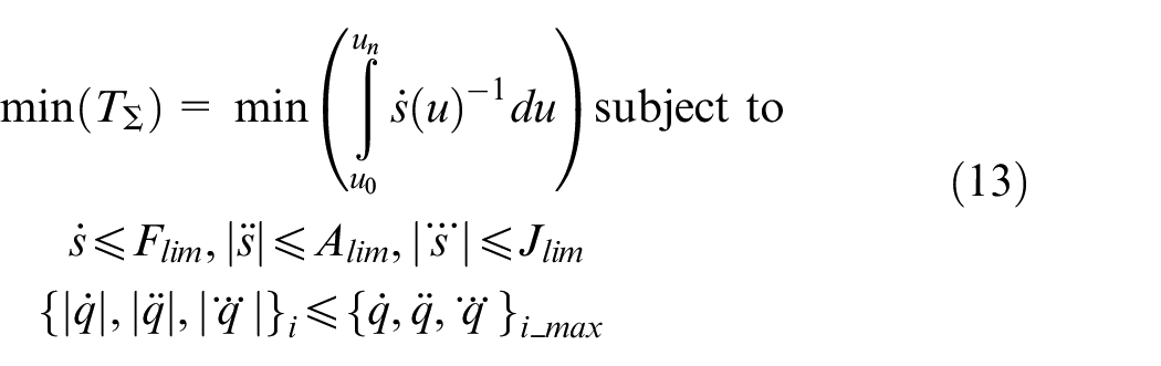
where
From equation (13), the constraints are nonlinear and coupled for the curve tool path, and it should be solved by the numerical method. There are many methods7,19 to address this problem. In this work, the method developed in Lu et al. 28 is used. Then, the feedrate scheduling results can be combined with the tool path geometry information to direct the movement of machine tools.
Real-time time-based interpolation and their corresponding machining data
As the feedrate scheduling method is also a numerical calculating method, the feedrate scheduling results are embedded in a large quantity of discrete points. Therefore, the mathematical form of the input data and the corresponding real-time interpolation should be designed simultaneously. In the proposed method, a time-based interpolator is designed to fulfill the last stage of processing.
In this study, a time-based B-spline is chosen to represent the feedrate scheduling results. The real-time interpolator is also a time-based B-spline interpolator, as presented in equation (14)
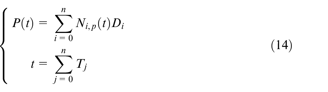
where t is the total machining time, Di are the control points, Ni,p(t) are the pth degree B-spline basis functions, and T is the interpolation period. Compared with other spline interpolators, the proposed B-spline interpolator does not need a feedrate scheduling algorithm and the interpolation accuracy can be guaranteed in the fitting process. As the tool path parameter is time, there is no need to estimate the tool path parameter by the arc length in each interpolation period. The interpolation period can be used as a tool path parameter directly.
The method of the knot vector and control points determining process is the same as the tool path fitting process. Compared with the tool path fitting process in section “Converting the G01 code to spline curve,” the smoothness of each axis position in every moment is better than that with G01 discrete points because the high-order derivatives of each axis position in every moment is limited in the feedrate scheduling process. However, the number of discrete axis positions is very large owing to the small calculation steps in the feedrate scheduling process. To improve the fitting process, the original data are split and fitted in each segment, and these fitted B-spline segments are united using the B-spline’s blending algorithm. 15 The B-spline’s blending algorithm is given as follows.
The fitted time-based B-spline curve for the ith segment is
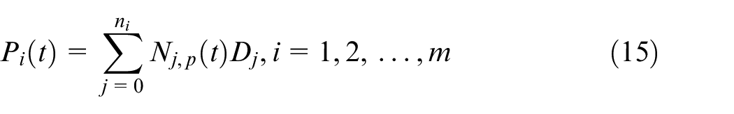
where m denotes the total segments, Dj are the control points, and Nj,p(t) are the pth degree B-spline basis functions formed by the knot vector

The whole time-based B-spline trajectory is
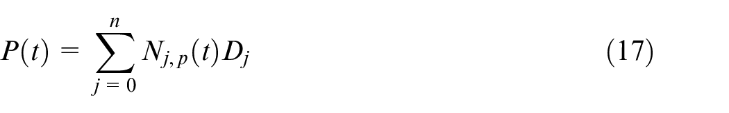
where
The control points
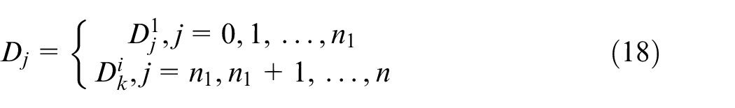
where
2.The knot vector
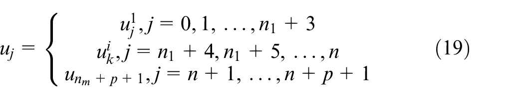
where
Calculation analysis
To verify the proposed method, two path trajectories of a part that has a sculpture surface are presented. The trajectory is designed for a denture to be machined in a five-axis machine and generated by the denture machining CAM HyperDENT. The tool path curves in the work piece coordinate system are presented in Figure 5. Each axis’ position is also provided in the figure.
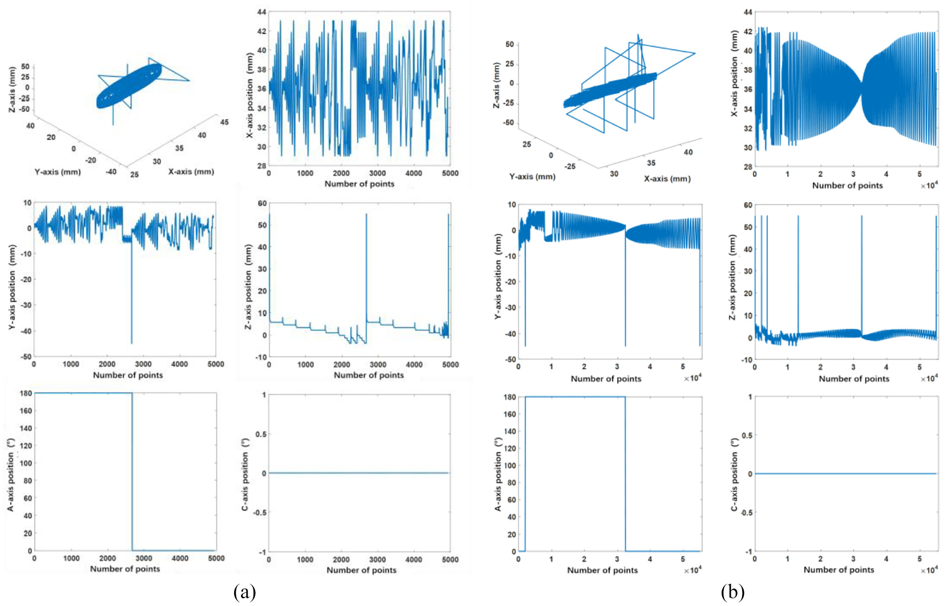
(a) Rough machining trajectory and (b) finish machining trajectory.
In the method, the G01 codes should be preprocessed to guarantee the fitting accuracy. According to the method, the whole G01 code should be divided at some extreme curvature points and the dividing method is just the angle between the two adjacent lines. In this work, the angle threshold is chosen as 15°. When the angle is less than the threshold, the whole G01 code is divided at that point. Then, the length of the whole trajectory should be uniformed to ensure the accuracy of the fitting process.
According to the method, the cubic B-spline is chosen to represent each segment of the trajectory, and the knot vector is distributed by the given accuracy requirements. To verify the given accuracy knot vector distribution method, different accuracy requirements are given for the B-spline fitting process. The knot vector is distributed by equation (12) and control points are calculated by the LS method. First, the relationship of the absolute maximum fitting error, absolute even fitting error, and number of control points with the given accuracy requirements are presented in Figure 6. As shown in the figures, with the given accuracy increasing, the number of control points decreases, and the absolute even fitting error increases almost linearly. This means that the method establishes the overall link between the B-spline fitting accuracy with the information of the original data to be fitted.
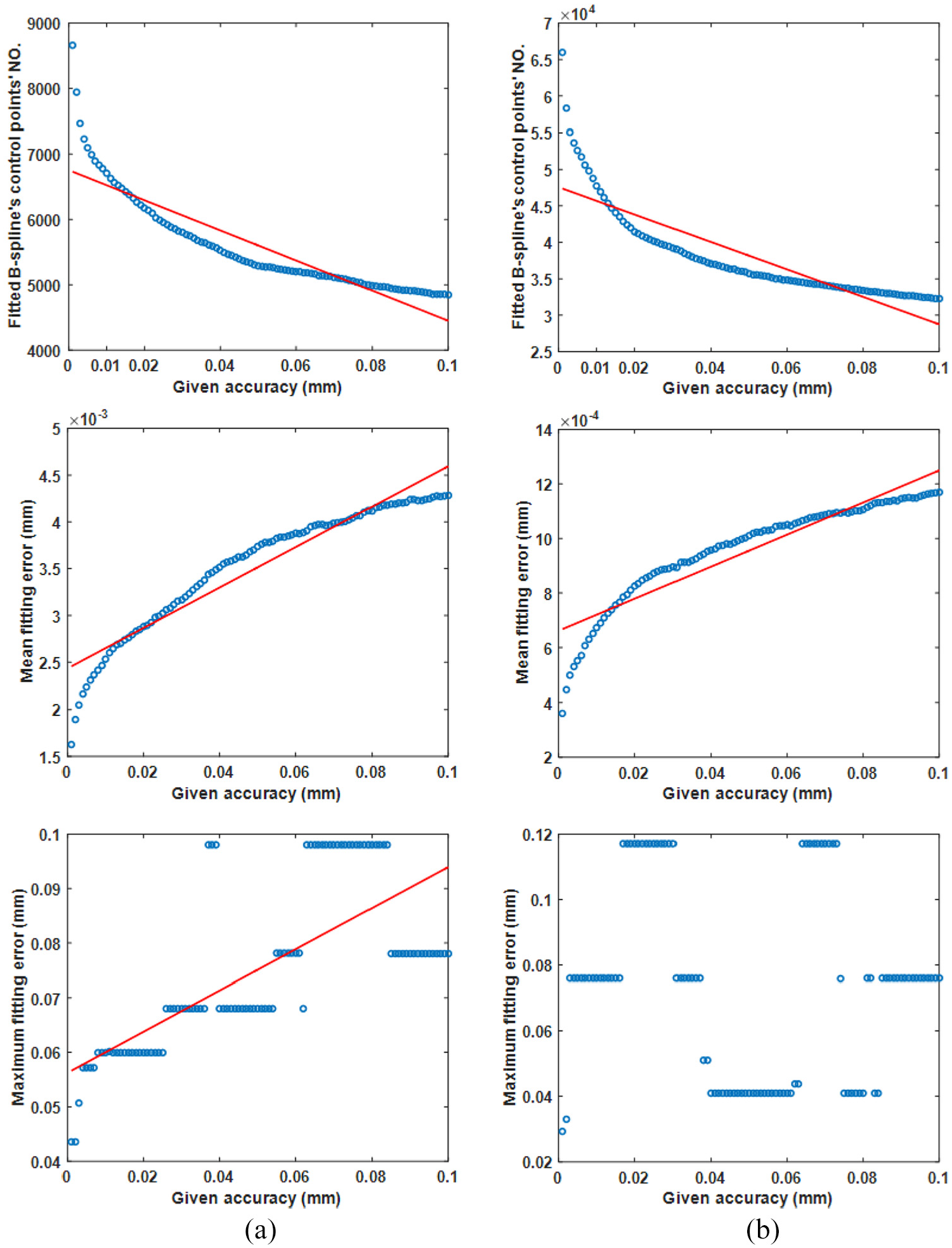
Relationships of the absolute maximum fitting error, absolute even fitting error, and number of control points with the given accuracy requirements: (a) rough machining trajectory and (b) finishing machining trajectory.
In the fitting process, the maximum fitting error always exists in the extreme curvature area or in the C0 continues area. In that place, the maximum fitting error has less sensitive to the little difference of the distribution of the knot vector. At the same time, the knot searching algorithm propagates forward unidirectionally and the new knot point is added when ε is larger than δ. Therefore, as shown in the last image in Figure 6, the relationship between the local maximum fitting error and the given accuracy is not obvious and the relation is unlike the relationship between the absolute even fitting error and given accuracy.
To further illustrate the knot distribution method, the distributions of the knot vector under different accuracy requirements in some areas are provided in Figure 7. From the figures, more knots will be distributed in the extreme curvature areas, that is, the areas in black circle as shown in Figure 7. At the same time, the number of knots increases as the accuracy requirements become higher.
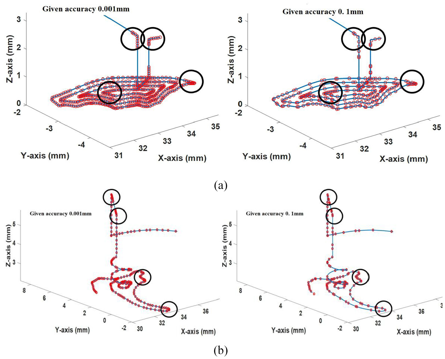
Knot vector distribution under different accuracy requirements in some areas: (a) part of rough machining trajectory and (b) part of finishing machining trajectory.
After obtaining the whole tool path in the form of a spline, the feedrate in every moment for the whole tool path is scheduled under given kinematical constraints to improve the smoothness of the machining process. The scheduled feedrate is presented in Figure 8. The axis position in every moment is obtained after the feedrate scheduling, and it is also shown in Figure 8.
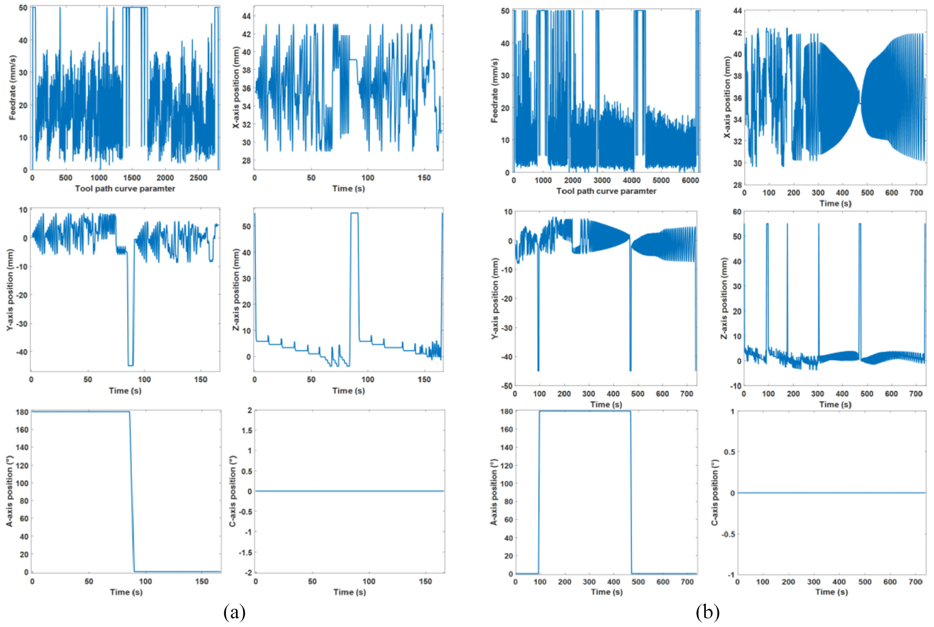
Feedrate profile and axis position in every moment: (a) rough machining trajectory and (b) finishing machining trajectory.
According to the method, the time parameter cubic B-spline is chosen as the real-time interpolator, and the time-discrete axis positions are transformed into the time parameter B-spline. Then the theoretical contour error can be calculated from the interpolation results and the original G01 code.
The contour error of the two segments of the tool path is presented in Figure 9. As shown in the figure, a larger contour error is shown in rough machining process. Comparatively, a smaller contour error is presented in the finishing machining process. This is because the finishing machining tool path is smoother. Therefore, the method is especially suitable for parts that have a freeform surface. Noted that the error is the difference between the interpolated result and the G01 code. The G01 code has contained the chord error in CAM process for using a line to represent the curve. But the method compensates the chord error due to use a curve to fit the short-line. Therefore, considering the chord error of G01 code, the theoretical contour error is relatively low.
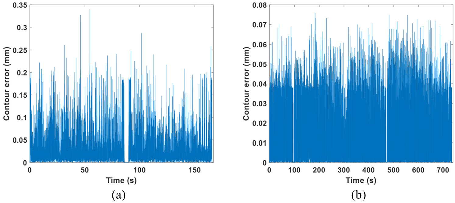
Contour error of the two segments of the tool path: (a) rough machining trajectory and (b) finishing machining trajectory.
Experiments
As the real-time controller is a time-based interpolator, the interpolator does not need real-time feedrate scheduling. It is used just to calculate the axis’ position according to the interpolation period and cubic B-spline function. The real-time interpolator is designed in the GSK CNC controller. Then, a hemispherical part is machined by the proposed method. The tool path profile and scheduled feedrate are presented in Figure 10. The machining process and machined part are presented in Figure 11. The experimental results verify the practicability of the proposed method.
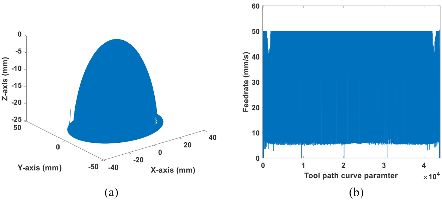
(a) Toolpath trajectory and (b) scheduled feedrate.
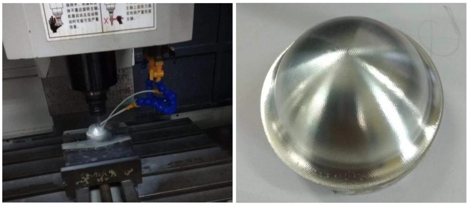
Machining process and machined result.
Conclusion
Traditionally, in the sculpture surface CNC machining process, the real-time controller is focused upon. In this work, a new machine tool movement control method that considers the advantages of both the real-time controller and CAM software is proposed. Many calculation-consuming modules are transferred from the real-time controller to the CAM software. To realize this process, many detailed technical problems are addressed.
First, the G01 code as the original tool path geometry data is fitted by cubic B-spline. Some technical measures and B-spline’s knot distribution method are presented to guarantee the fitting process. Then, the machining process is planned by the feedrate scheduling method to improve the machining efficiency under the limits of the machine tools’ capacity and requirements of the machine process technique. Finally, the real-time interpolator and the mathematical form of the axis position in each moment obtained from the feedrate scheduling are designed simultaneously. In the real-time controller, the time parameter B-spline is chosen as the interpolator. The interpolator requires less real-time calculation, and the accuracy is guaranteed by the CAM software calculation process. The calculation process is analyzed by a calculation case, and the method is verified by an experiment. Furthermore, more optimization modules will be embedded in this software and make the machining process and results more controllable.
Footnotes
Acknowledgements
The author L.L. appreciates the comments and discussion with Dr Hao Wang at NUS.
Declaration of conflicting interests
The author(s) declared no potential conflicts of interest with respect to the research, authorship, and/or publication of this article.
Funding
The author(s) disclosed receipt of the following financial support for the research, authorship, and/or publication of this article: This work was supported by the National Natural Science Foundation of China (Grant Nos 51705120 and 51805135), the Natural Science Foundation of Anhui Province (Grant No. 1808085QE139), and the China Scholarship Council (CSC).